2009 Chevrolet Tahoe, Suburban Owner Manual M
2009 Chevrolet Tahoe, Suburban Owner Manual M
GENERAL MOTORS, GM, the GM Emblem, CHEVROLET, the CHEVROLET Emblem, and the names TAHOE, SUBURBAN, and Z71 are registered trademarks of General Motors Corporation.
This manual includes the latest information at the time it was printed. GM reserves the right to make changes
in the product after that time without notice. For vehicles ???rst sold in Canada, substitute the name ???General Motors of Canada Limited??? for Chevrolet Motor Division wherever it appears in this manual.
This manual describes features that may or may not be on your speci???c vehicle.
Read this manual from beginning to end to learn about the vehicle???s features and controls. Pictures, symbols, and words work together to explain vehicle operation.
Litho in U.S.A.
Part No. 15911385 B Second Printing
If your vehicle is a
Keep this manual in the vehicle for quick reference.
Canadian Owners
Canadian Owners (Propri??taires
Canadiens)
A French language copy of this manual can be obtained from your dealer/retailer or from:
On peut obtenir un exemplaire de ce guide en fran??ais aupr??s du concessionnaire ou ?? l???adresse suivante:
Helm, Incorporated
P.O. Box 07130
Detroit, MI 48207
Num??ro de poste 6438 de langue fran??aise www.helminc.com
?? 2008 General Motors Corporation. All Rights Reserved.
iii

Index
To quickly locate information about the vehicle, use the index in the back of the manual. It is an alphabetical
list of what is in the manual and the page number where it can be found.
Safety Warnings and Symbols
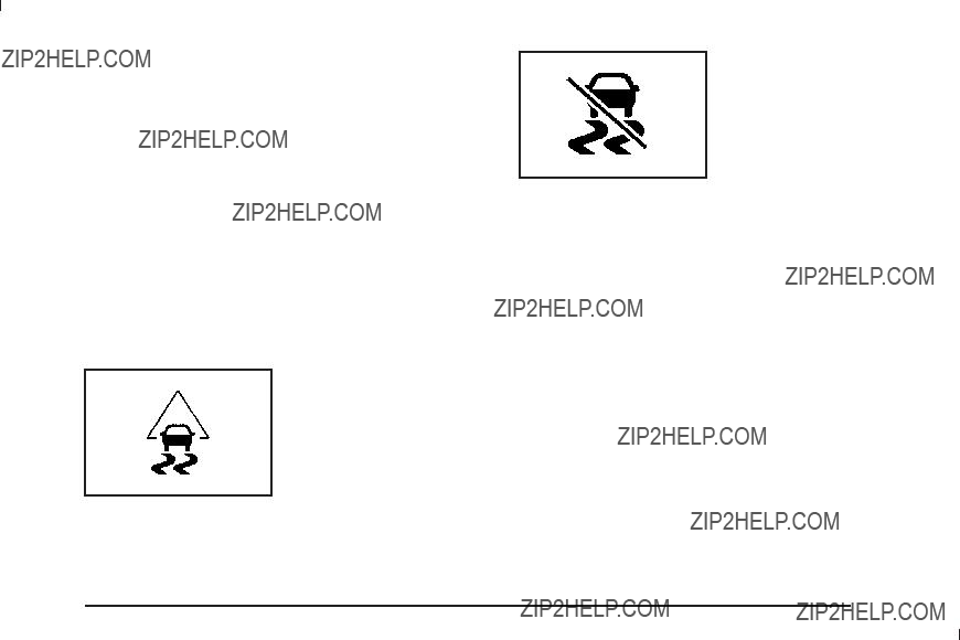
A circle with a slash through it is a safety symbol which means ???Do Not,??? ???Do not do this,???
or ???Do not let this happen.???
A box with the word CAUTION is used to tell about things that could hurt you or others if you were to ignore the warning.
{ CAUTION:
These mean there is something that could hurt you or other people.
Cautions tell what the hazard is and what to do to avoid or reduce the hazard. Read these cautions.
A notice tells about something that can damage the vehicle.
Notice: These mean there is something that could damage your vehicle.
Many times, this damage would not be covered by the vehicle???s warranty, and it could be costly. The notice tells what to do to help avoid the damage.
There are also warning labels on the vehicle which use the same words, CAUTION or Notice.
Vehicle Symbols
The vehicle has components and labels that use symbols instead of text. Symbols are shown along with the text describing the operation or information relating to a speci???c component, control, message, gage, or indicator.
M : This symbol is shown when you need to see your owner manual for additional instructions or information.
* : This symbol is shown when you need to see a service manual for additional instructions or information.
iv

Vehicle Symbol Chart
Here are some additional symbols that may be found on the vehicle and what they mean. For more information on the symbol, refer to the index.
0 : Adjustable Pedals
9 : Airbag Readiness Light
# : Air Conditioning
! : Antilock Brake System (ABS)
g : Audio Steering Wheel Controls or OnStar??
$ : Brake System Warning Light
" : Charging System
I : Cruise Control
B : Engine Coolant Temperature
O : Exterior Lamps
# : Fog Lamps
. : Fuel Gage
+ : Fuses
i : Headlamp
j : LATCH System Child Restraints
* : Malfunction Indicator Lamp
: : Oil Pressure
g : Outside Power Foldaway Mirrors
} : Power
/ : Remote Vehicle Start
> : Safety Belt Reminders
7 : Tire Pressure Monitor
_ : Tow/Haul Mode
F : Traction Control
M : Windshield Washer Fluid
v
??? NOTES
vi
Section 1 Seats and Restraint System
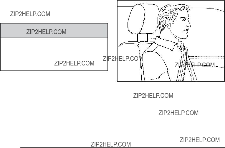
Head Restraints
The front seats have adjustable head restraints in the outboard seating positions.
{ CAUTION:
With head restraints that are not installed and adjusted properly, there is a greater chance that occupants will suffer a neck/spinal injury in a crash. Do not drive until the head restraints for all occupants are installed and adjusted properly.
Adjust the head restraint so that the top of the restraint is at the same height as the top of the occupant???s head. This position reduces the chance of a neck injury in a crash.
Push down on the head restraint after the button is released to make sure that it is locked in place.
The head restraints are not designed to be removed.
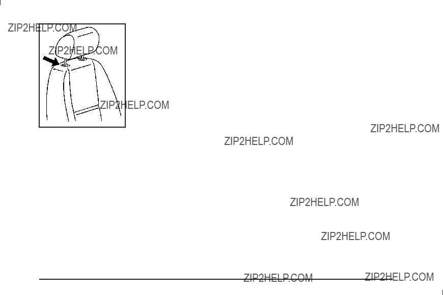
The rear seat has head rests that can be adjusted up and down.
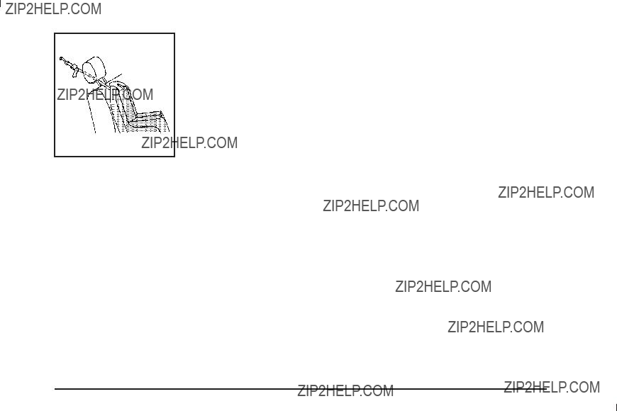
Pull the head restraint up to raise it. To lower the head restraint, press the button, located on the top of the seatback, and push the restraint down.
Front Seats
Manual Seats
{ CAUTION:
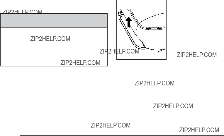
You can lose control of the vehicle if you try to adjust a manual driver???s seat while the vehicle is moving. The sudden movement could startle and confuse you, or make you push a pedal when you do not want to. Adjust the driver???s seat only when the vehicle is not moving.
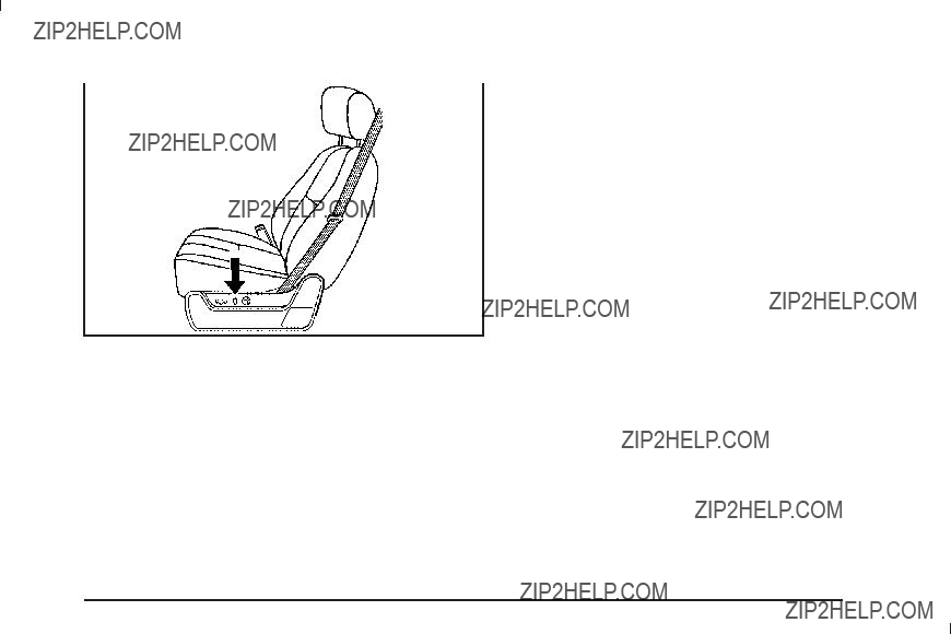
If the vehicle has a manual seat, it can be moved forward or rearward.
1. Lift the bar to unlock the seat.
2. Slide the seat to the desired position and release the bar.
Try to move the seat with your body to be sure the seat is locked in place.
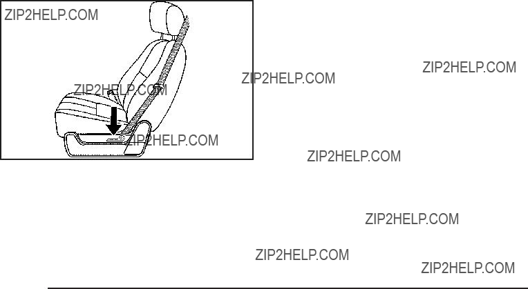
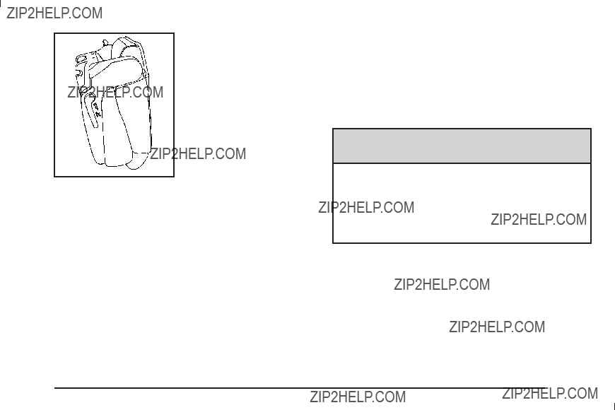
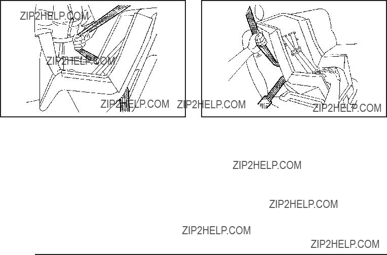
Power Seats
Driver???s Seat with Power Seat Control, Power Recline, and Power Lumbar shown
On a vehicle with power seats, the controls used to operate them are located on the outboard side of the seats.
Move the seat forward or rearward by sliding the control forward or rearward.
Your vehicle may have additional features to adjust your vehicle???s power seat:
???Raise or lower the front part of the seat cushion by moving the front of the control up or down.
???Raise or lower the rear part of the seat cushion by moving the rear of the control up or down.
???Raise or lower the entire seat by moving the entire control up or down.
On seats with power reclining seatbacks, the control is located behind the power seat control on the outboard side of the seats. See ???Power Reclining Seatbacks??? under Reclining Seatbacks on page
A vehicle with a memory function allows seat settings to be saved and recalled. See Memory Seat, Mirrors,
and Pedals on page

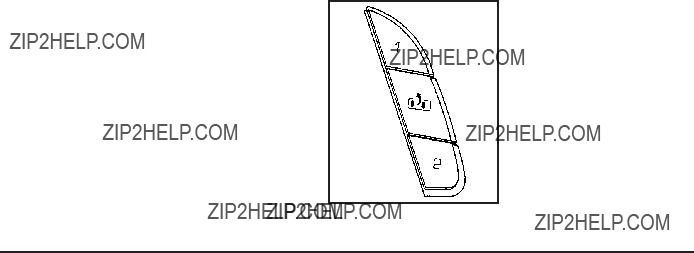
On vehicles with this feature the control is located on the outboard side of the seat.
Increase or decrease lumbar support by turning the knob forward or rearward.
On seats with power lumbar, the controls used to operate this feature are located on the outboard side of the seats.
???To increase lumbar support, press and hold the front of the control.
???To decrease lumbar support, press and hold the rear of the control.

The vehicle may have additional features to adjust your vehicle???s power seat:
???To raise the height of the lumbar support, press and hold the top of the control.
???To lower the height of the lumbar support, press and hold the bottom of the control.
Release the control when the lower seatback reaches the desired level of lumbar support.
Your vehicle may have a memory function which allows seat settings to be saved and recalled. See Memory Seat, Mirrors, and Pedals on page
Keep in mind that as your seating position changes, as it may during long trips, so should the position of
your lumbar support. Adjust the seat as needed.
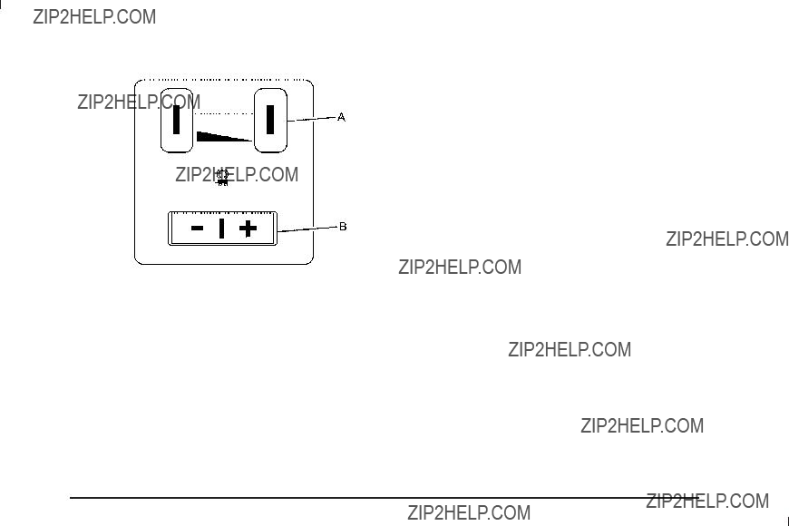
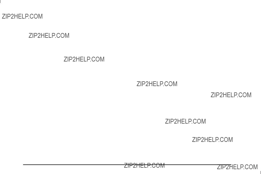
Heated Seats
On vehicles with heated front seats, the controls are located on the driver and passenger doors.
I (Heated Seatback): Press to turn on the heated seatback.
J (Heated Seat and Seatback): Press to turn on the
heated seat and seatback.
The light on the button will come on to indicate that the feature is working. Press the button to cycle through the temperature settings of high, medium, and low and to turn the heat to the seat off. Indicator lights will show the level of heat selected: three for high, two for medium, and one for low.
The heated seats will be canceled 10 seconds after the ignition is turned off. To use the heated seat feature after restarting the vehicle, press the heated seat
or seatback button again.
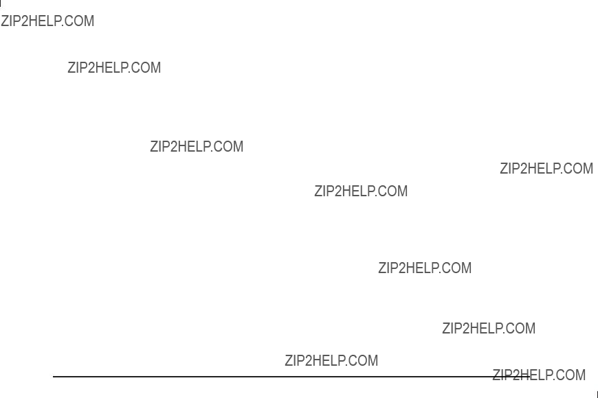
Heated and Cooled Seats
If the front seats have the heated and cooled seat feature, the buttons used to control this feature
are located on the front doors near the door handle.
{ (Cooled Seat): To cool the entire seat, press the button with the cooled seat symbol.
This symbol will appear on the climate control display to indicate that the feature is on. Press the button to
cycle through the temperature settings of high, medium, and low and to turn the cooled seat off. Indicator
bars next to the symbol designate the level of cooling selected: three for high, two for medium, and one
for low.
+ (Heated Seatback): To heat only the seatback, press the button with the heated seatback symbol.
This symbol will appear on the climate control display to indicate that the feature is on. Press the button to cycle through the temperature settings of high, medium, and low and to turn the heated seatback off. Indicator bars next to the symbol designate the level of heat selected: three for high, two for medium, and one for low.
z (Heated Seat and Seatback): To heat the entire seat, press the button with the heated seat and seatback symbol.
This symbol will appear on the climate control display to indicate that the feature is on. Press the button to cycle through the temperature settings of high, medium, and low and to turn the heated seat off. Indicator bars next to the symbol designate the level of heat selected: three for high, two for medium, and one for low.
The heated and cooled seats will be canceled after the ignition is turned off. To use the heated and cooled seat feature after the vehicle is started, you will need to press the appropriate seat button again.
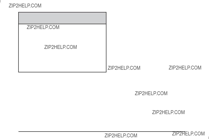
Memory Seat, Mirrors, and Pedals
Your vehicle may have the memory package.
The controls for this feature are located on the driver???s door panel, and are used to program
and recall memory settings for the driver???s seat, outside mirrors, and the adjustable throttle and brake pedal.

To save seating positions in memory:
1.Adjust the driver???s seat, including the seatback recliner and lumbar, both outside mirrors, and the throttle and brake pedals to a comfortable position.
See Outside Power Mirrors on page
Not all mirrors, adjustable throttles and brake pedals, or power lumbar will have the ability to save and recall their positions.
2.Press and hold button 1 until two beeps sound to indicate that the position has been stored.
A second seating, lumbar, mirror, and throttle and brake pedal position can be programmed by repeating the above steps and pressing button 2.
To recall the memory positions, the vehicle must be in PARK (P). Press and release either button 1 or button 2 corresponding to the desired driving position. The
seat, outside mirrors, and adjustable throttle and brake pedals will move to the position previously stored. You will hear a single beep.
If you use the remote keyless entry transmitter to enter your vehicle and the remote recall memory feature
is on, automatic seat, adjustable mirror, and adjustable pedal movements will occur. See ???MEMORY SEAT RECALL??? under DIC Vehicle Customization (With DIC Buttons) on page
To stop recall movement of the memory function at any time, press one of the power seat controls, memory buttons, power mirror buttons, or adjustable pedal switch.
If something has blocked the driver???s seat and/or the adjustable pedals while recalling a memory position, the driver???s seat and/or the adjustable pedals recall may stop working. If this happens, remove the obstruction and press the appropriate control for the area that is not responding for two seconds. Try recalling the memory position again by pressing the appropriate memory button. If the memory position is still not recalling, see your dealer for service.
Easy Exit Seat
The control for this feature is located on the driver???s door panel between buttons 1 and 2.
With the vehicle in PARK (P), the driver???s seat exit position can be recalled by pressing the exit button. You will hear a single beep, and the driver???s seat will
move back.
If the easy exit seat feature is programmed in the Driver Information Center (DIC), automatic seat movement
will occur when the key is removed from the ignition. See ???EASY EXIT SEAT??? under DIC Vehicle Customization (With DIC Buttons) on page
The memory seat and easy exit features can also be programmed using the DIC.
For programming information, see DIC Vehicle Customization (With DIC Buttons) on page
Reclining Seatbacks
{ CAUTION:
You can lose control of the vehicle if you try to adjust a manual driver???s seat while the vehicle is moving. The sudden movement could startle and confuse you, or make you push a pedal when you do not want to. Adjust the driver???s seat only when the vehicle is not moving.
{ CAUTION:
If either seatback is not locked, it could move forward in a sudden stop or crash. That could cause injury to the person sitting there. Always push and pull on the seatbacks to be sure they are locked.

{ CAUTION:
Sitting in a reclined position when your vehicle is in motion can be dangerous. Even if you buckle up, your safety belts cannot do their job when you are reclined like this.
The shoulder belt cannot do its job. In a crash, you could go into it, receiving neck or other injuries.
The lap belt cannot do its job either. In a crash the belt could go up over your abdomen. The belt forces would be there, not at your pelvic bones. This could cause serious internal injuries.
For proper protection when the vehicle is in motion, have the seatback upright. Then sit well back in the seat and wear your safety belt properly.
Manual Reclining Seatbacks
On seats with manual reclining seatbacks, the lever used to operate them is located on the outboard side of the seat(s).
To recline the seatback:
1.Lift the recline lever.
2.Move the seatback to the desired position, then release the lever to lock the seatback in place.
3.Push and pull on the seatback to make sure it is locked.
To return the seatback to an upright position, do the following:
1.Lift the lever fully without applying pressure to the seatback and the seatback will return to the upright position.
2.Push and pull on the seatback to make sure it is locked.
Center Seat
Your vehicle may have a front center seat. The seatback doubles as an armrest and cupholder/storage area for the driver and passenger when the center seat is
not used. Do not use it as a seating position when the seatback is folded down.

Rear Seats
Heated Seats
On vehicles with rear outboard heated seats, the buttons used to control this feature are located on the Rear Seat Audio (RSA) panel.
Driver Side RSA Heated
Seat Button shown
M (Heated Seat): To heat the seat cushion, press the button with the heated seat symbol.
A heated seat symbol will be shown in the RSA display to indicate that the feature is on. Press the button to cycle through the temperature settings of high, medium, and low, and to turn it off. Indicator bars next to the symbol will designate the level of heat selected: three for high, two for medium, and one for low.
The heated seats are off when the ignition is off.
60/40 Split Bench Seat
(Second Row)
If your vehicle has a 60/40 split bench, the seat(s) can be folded for additional cargo space or folded and tumbled for easy entry and exit to the third row seats, if your vehicle has them. These seats will have either
the manual fold and tumble feature or the automatic seat release fold and tumble feature.
Manual Fold and Tumble Feature
Folding and Tumbling the Seat(s)
To fold and tumble the seat, do the following:
1.Make sure that there is nothing under, in front of, or on the seat.
Notice: Folding a rear seat with the safety belts still fastened may cause damage to the seat or the safety belts. Always unbuckle the safety belts and return them to their normal stowed position before folding a rear seat.
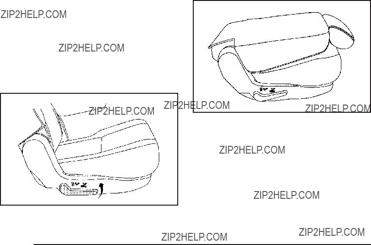
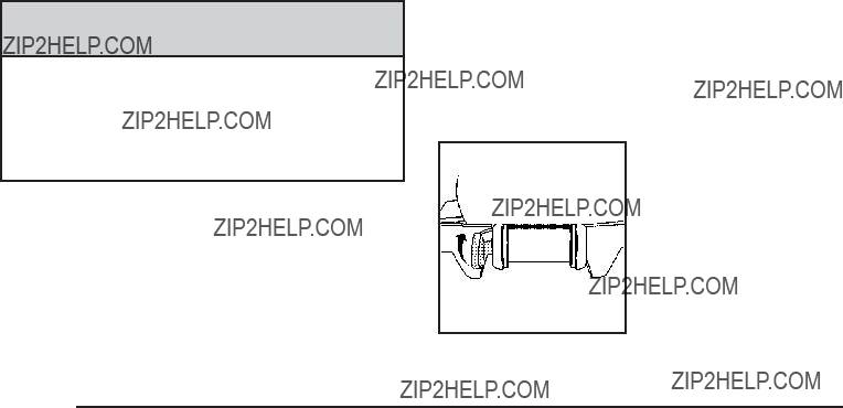
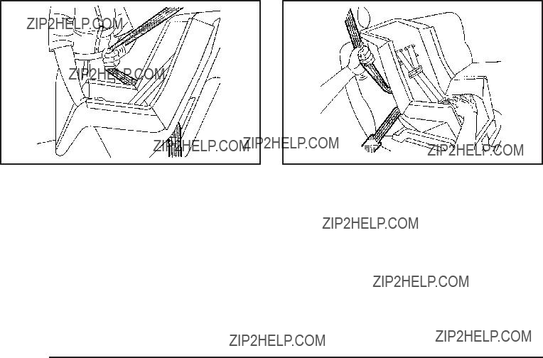
2.Lift the lever, located on the outboard side of the seat, to release the seatback.
The seatback will fold forward automatically. Leaving the seatback in this position creates a ???at load ???oor.
If the seatback cannot fold ???at, try moving the front seat forward and/or put the front seatback in the upright position.

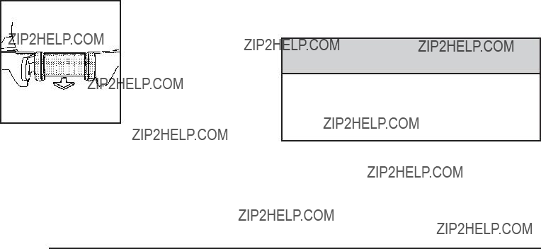
3.Lift the same lever again to release the rear of the seat
from the ???oor. The seat will tumble forward.
{ CAUTION:
If either seatback is not locked, it could move forward in a sudden stop or crash. That could cause injury to the person sitting there. Always push and pull on the seatbacks to be sure they are locked.
2.Lift the seatback and push it rearward. Push and pull on the seatback to make sure it is locked.
Returning the Seat(s) to the Sitting Position
To return the seat to the sitting position, do the following:
1.Pull the seat down until it latches to the ???oor. The seatback cannot be raised if the seat is not latched to the ???oor.
{ CAUTION:
A safety belt that is improperly routed, not properly attached, or twisted will not provide the protection needed in a crash. The person wearing the belt could be seriously injured. After raising the rear seatback, always check to be sure that the safety belts are properly routed and attached, and are not twisted.
3.Make sure the safety belt in the center seating position is not caught between the two seats and is not twisted.
Folding and Tumbling the Seat(s) from the Third Row Seats
{ CAUTION:
Using the third row seating position while the second row is folded, or folded and tumbled, could cause injury in a sudden stop or crash. Be sure to return the seat to the passenger seating position. Push and pull on the seat to make sure it is locked into place.
To fold and tumble the seat from the third rows, if your vehicle has them, do the following:
1.Make sure that there is nothing under, in front of, or on the seat.
Notice: Folding a rear seat with the safety belts still fastened may cause damage to the seat or the safety belts. Always unbuckle the safety belts and return them to their normal stowed position before folding a rear seat.
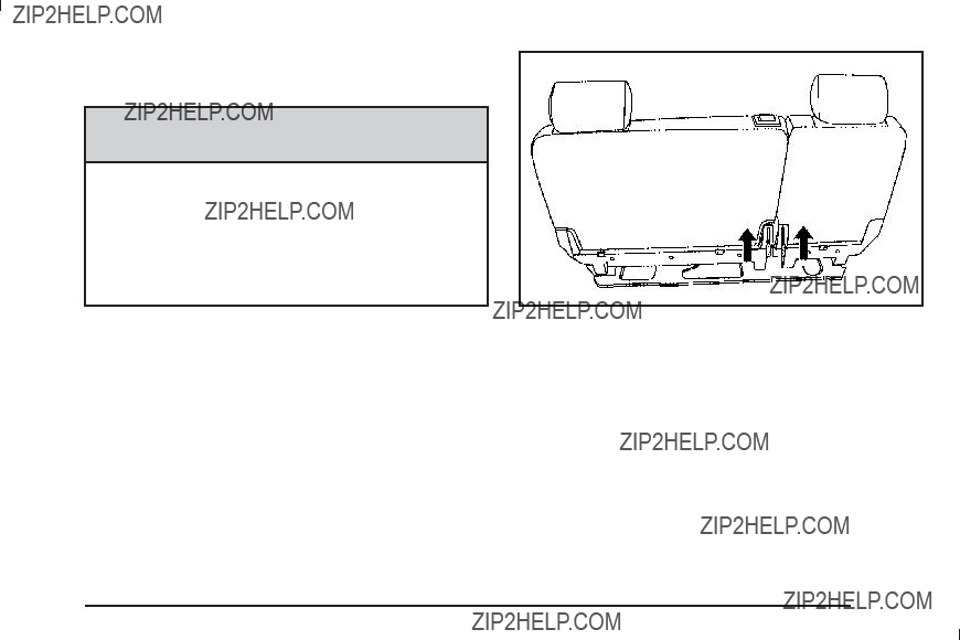
2.Lift the lever(s), located on the bottom rear of the second row seat(s) on the inboard side, to release the seatback. The seatback will fold forward.
3.Lift the same lever again to release the rear of the seat from the ???oor. The seat will tumble forward automatically.
Power Release Fold and Tumble
Feature
The transmission must be in (P) Park for this feature to work.
Folding and Tumbling the Seat(s)
{ CAUTION:
Automatically folding and tumbling the seat when someone is sitting in the seat, could cause injury to the person sitting there. Always make sure there is no one sitting in the seat before pressing the automatic seat release button.
To fold and tumble the seat, do the following:
1.Make sure that there is nothing under, in front of, or on the seat.
Notice: Folding a rear seat with the safety belts still fastened may cause damage to the seat or the safety belts. Always unbuckle the safety belts and return them to their normal stowed position before folding a rear seat.
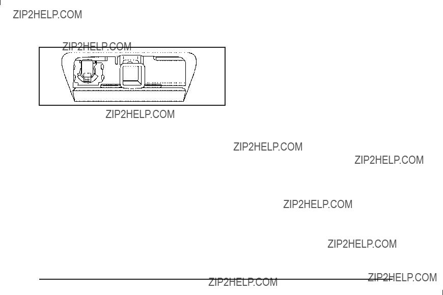
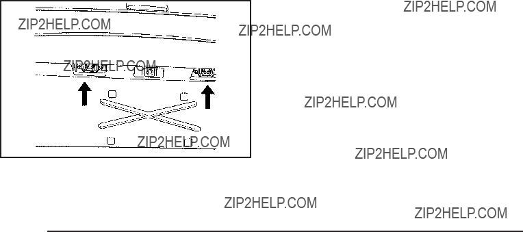
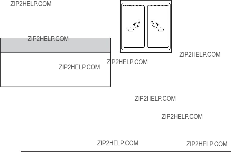
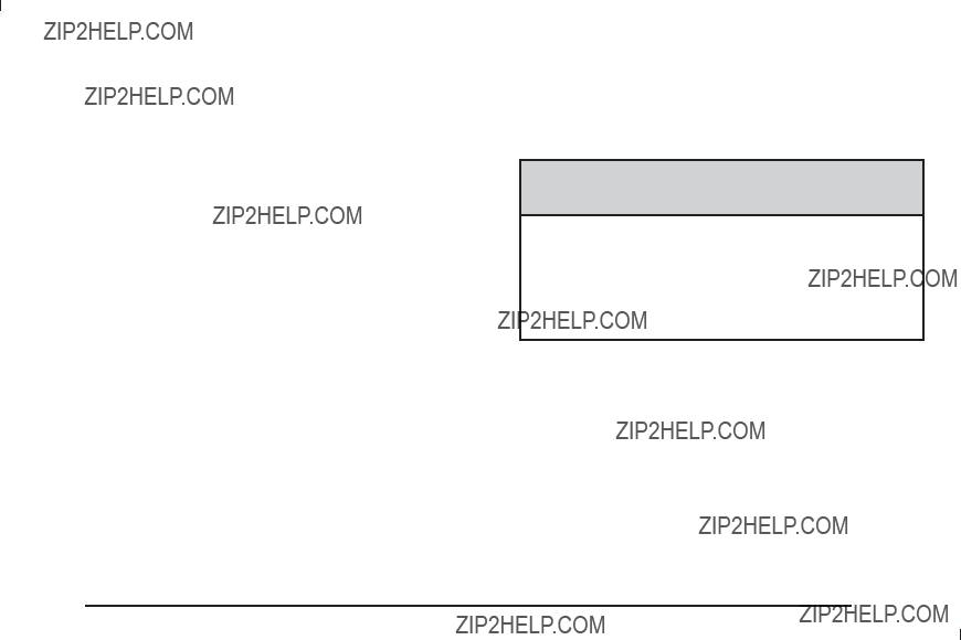
2. From the front seats, press one of the automatic seat release buttons located on the overhead console.
Overhead Console
Buttons shown, Panel
Button similar
When accessing the third row seats, if your vehicle has them, from the outside of the vehicle, press the button on the panel behind either rear door.
One press of the button automatically folds the seatback ???at and tumbles the seat forward.
There will be a slight delay between the folding of the seatback and the tumbling of the seat.

Returning the Seat(s) to the Sitting Position
To return the seat to the sitting position, do the following:
1.Pull the seat down until it latches to the ???oor. The seatback cannot be raised if the seat is not latched to the ???oor.
{CAUTION:
If either seatback is not locked, it could move forward in a sudden stop or crash. That could cause injury to the person sitting there. Always push and pull on the seatbacks to be sure they are locked.
2.Lift the seatback and push it rearward. Push and pull on the seatback to make sure it is locked.
{ CAUTION:
A safety belt that is improperly routed, not properly attached, or twisted will not provide the protection needed in a crash. The person wearing the belt could be seriously injured. After raising the rear seatback, always check to be sure that the safety belts are properly routed and attached, and are not twisted.
3.Make sure that the safety belt in the center seating position is not caught between the two seats and is not twisted.
Folding and Tumbling the Second Row Seat(s) from the Third Row Seats or Outside
{ CAUTION:
Using the third row seating position while the second row is folded, or folded and tumbled, could cause injury in a sudden stop or crash. Be sure to return the seat to the passenger seating position. Push and pull on the seat to make sure it is locked into place.
To fold and tumble the seat from the third row seats, if your vehicle has them, do the following:
1.Make sure that there is nothing under, in front of, or on the seat.
Notice: Folding a rear seat with the safety belts still fastened may cause damage to the seat or the safety belts. Always unbuckle the safety belts and return them to their normal stowed position before folding a rear seat.
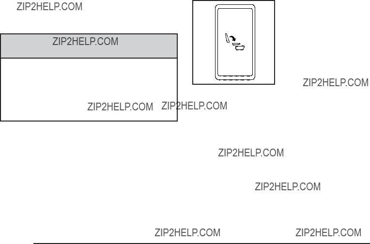
2. Press the automatic seat release button located on the panel behind the rear doors.
Driver???s Side Rear Panel
Button shown
One press of the button automatically folds the seatback ???at and tumbles the seat forward. There will be a slight delay between the folding of the seatback and the tumbling of the seat.
Bucket Seats (Second Row)
If your vehicle has bucket seats, the seatbacks can be reclined, the seats can be folded for additional cargo space, or folded and tumbled for easy entry and exit to the third row seats, if your vehicle has them. These seats will have either the manual fold and tumble feature or the automatic seat release fold and tumble feature.

Reclining Seatbacks
To recline the seatback, do the following:
1.Lift the lever located on the outboard side of the seat.
2.Move the seatback to the desired position, then release the lever to lock the seatback in place.
3.Push and pull on the seatback to make sure it is locked.
To return the seatback to an upright position, do the following:
1.Lift the lever fully without applying pressure to the seatback and the seatback will return to the upright position.
{CAUTION:
If either seatback is not locked, it could move forward in a sudden stop or crash. That could cause injury to the person sitting there. Always push and pull on the seatbacks to be sure they are locked.
2.Push and pull on the seatback to make sure it is locked.
Manual Fold and Tumble Feature
Folding and Tumbling the Seat(s)
To fold and tumble the seat, do the following:
1.Make sure that there is nothing under, in front of, or on the seat.
Notice: Folding a rear seat with the safety belts still fastened may cause damage to the seat or the safety belts. Always unbuckle the safety belts and return them to their normal stowed position before folding a rear seat.
2.Lift the lever, located on the outboard side of the seat, to release the seatback.
The seatback will fold forward. Leaving the seatback in this position creates a ???at load ???oor.
If the seatback cannot fold ???at, try moving the front seat forward and/or put the front seatback in the upright position.
3.Lift the lever again to release the rear of the seat from the ???oor.
The seat will tumble forward.
Returning the Seat(s) to the Sitting Position
To return the seat to the sitting position, do the following:
1.Pull the seat down until it latches to the ???oor. The seatback cannot be raised if the seat is not latched to the ???oor.
{CAUTION:
If either seatback is not locked, it could move forward in a sudden stop or crash. That could cause injury to the person sitting there. Always push and pull on the seatbacks to be sure they are locked.
2.Lift the seatback and push it rearward. Push and pull on the seatback to make sure it is locked.

Folding and Tumbling the Seat(s) from the Third Row Seats
{ CAUTION:
Using the third row seating position while the second row is folded, or folded and tumbled, could cause injury in a sudden stop or crash. Be sure to return the seat to the passenger seating position. Push and pull on the seat to make sure it is locked into place.
To fold and tumble the seat from the third row seats, if your vehicle has them:
1.Make sure that there is nothing under, in front of, or on the seat.
Notice: Folding a rear seat with the safety belts still fastened may cause damage to the seat or the safety belts. Always unbuckle the safety belts and return them to their normal stowed position before folding a rear seat.
2. Lift the lever, located on the bottom rear of the second row seat on the inboard side, to release the seatback. The seatback will
fold forward.
3.Lift the lever again to release the rear of the seat from the ???oor. The seat will tumble forward.
Power Release Fold and Tumble
Feature
The transmission must be in (P) Park for this feature to work.
Folding and Tumbling the Seat(s)
{ CAUTION:
Automatically folding and tumbling the seat when someone is sitting in the seat, could cause injury to the person sitting there. Always make sure there is no one sitting in the seat before pressing the automatic seat release button.
To fold and tumble the seat, do the following:
1.Make sure that there is nothing under, in front of, or on the seat.
Notice: Folding a rear seat with the safety belts still fastened may cause damage to the seat or the safety belts. Always unbuckle the safety belts and return them to their normal stowed position before folding a rear seat.
2. From the front seats, press one of the automatic seat release buttons located on the overhead console.
Overhead Console
Buttons shown
When accessing the third row seats, if your vehicle has them, from the outside of the vehicle, press the button on the panel behind either rear door.
One press of the button automatically folds the seatback ???at and tumbles the seat forward.
There will be a slight delay between the folding of the seatback and the tumbling of the seat.

Returning the Seat(s) to the Sitting Position
To return the seat to the sitting position, do the following:
1.Pull the seat down until it latches to the ???oor. The seatback cannot be raised if the seat is not latched to the ???oor.
{CAUTION:
If either seatback is not locked, it could move forward in a sudden stop or crash. That could cause injury to the person sitting there. Always push and pull on the seatbacks to be sure they are locked.
2.Lift the seatback and push it rearward. Push and pull on the seatback to make sure it is locked.
Folding and Tumbling the Second Row Seat(s) from the Third Row Seats or Outside
{ CAUTION:
Using the third row seating position while the second row is folded, or folded and tumbled, could cause injury in a sudden stop or crash. Be sure to return the seat to the passenger seating position. Push and pull on the seat to make sure it is locked into place.
To fold and tumble the seat from the third row seats, if your vehicle has them, do the following:
1.Make sure that there is nothing under, in front of, or on the seat.
Notice: Folding a rear seat with the safety belts still fastened may cause damage to the seat or the safety belts. Always unbuckle the safety belts and return them to their normal stowed position before folding a rear seat.

2. Press the automatic seat release button located on the panel behind the rear doors.
Driver???s Side Rear Panel
Button shown
One press of the button automatically folds the seatback ???at and tumbles the seat forward. There will be a slight delay between the folding of the seatback and the tumbling of the seat.
Third Row Seat
If the vehicle has a third row seat, the seatback(s) can be folded and the entire seat can be tumbled, or removed from the vehicle.
Folding the Seatback(s)
To fold the seatback, do the following:
1.Open the liftgate to access the controls for the seat.
2.Remove all items on the seat cushion.
Notice: Folding a rear seat with the safety belts still fastened may cause damage to the seat or the safety belts. Always unbuckle the safety belts and return them to their normal stowed position before folding a rear seat.
3. Lift the release lever, located on the bottom rear of the seatback on the outboard side of the seat, and the
seatback will fold forward.
Unfolding the Seatback(s)
To return the seatback to the upright position, do the following:
1.Open the liftgate to access the controls for the seat.
2.Pull up on the seatback until it locks into the upright position.
{CAUTION:
If either seatback is not locked, it could move forward in a sudden stop or crash. That could cause injury to the person sitting there. Always push and pull on the seatbacks to be sure they are locked.
3.Push and pull on the seatback to make sure it is locked.
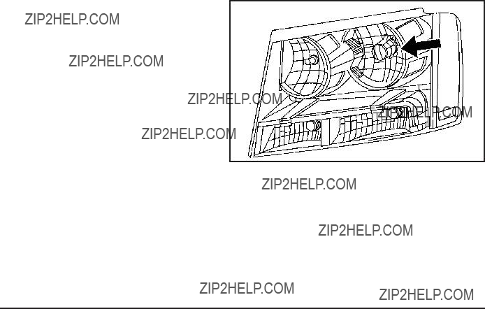
Tumbling the Third Row Seat
The seat can be tumbled forward for additional cargo space.
To tumble the seat, do the following:
1.Open the liftgate to access the controls for the seat.
2.Make sure the head rests are completely lowered, there is nothing under, in front of, or on the seat, and all items are removed from the cupholder
and storage bin, if the seat is a
3.Fold the seatbacks forward using the instructions previously listed under ???Folding the Seatbacks???. You will not be able to unlatch the seat from
the ???oor unless the seatback is folded down.
4.Unlatch the seat from the ???oor by lifting the lever located next
to the carrying handle on the rear of the seat near the bottom.
5. Lift the rear of the seat up from the ???oor.
6.Tilt the seat fully forward to lock it into place.
7.Push and pull on the seat to make sure it is locked.
Put the seat in this position only when necessary for additional cargo space.
Returning the Third Row Seat from a Tumbled Position
To return the seat to the normal seating position, do the following:
1.Open the liftgate to access the controls for the seat.
2.Make sure there is nothing that could become trapped under the seat.
3.Release the seat from the tumbled position by lifting the lever located next to the carrying handle at the bottom rear of the seat.
4.Pull the seat down until it latches to the ???oor. The seatback cannot be raised if the seat is not latched to the ???oor.
5.Pull up on the seatback until it locks into the upright position.
{CAUTION:
If either seatback is not locked, it could move forward in a sudden stop or crash. That could cause injury to the person sitting there. Always push and pull on the seatbacks to be sure they are locked.
6.Push and pull on the seatback to make sure it is locked.
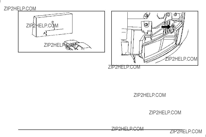
Removing the Third Row Seat
To remove the seat, do the following:
1.Open the liftgate to access the controls for the seat.
2.Fold the seatback forward using the instructions listed under ???Folding the Seatbacks??? previously. The seat cannot be removed unless the seatback is folded.
3.Unlatch the seat from the ???oor by pulling the carrying handle, located at the rear of the seat, rearward.
4.Roll the seat out of the vehicle. There is a track in the ???oor to guide the seat wheels out of the vehicle.
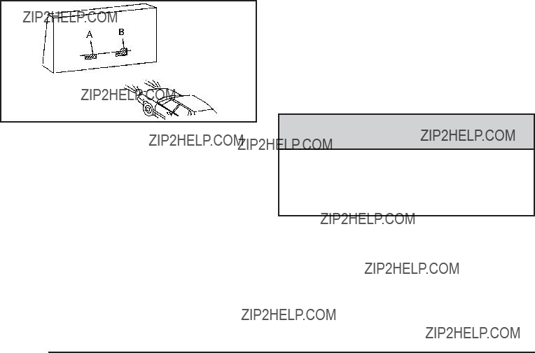
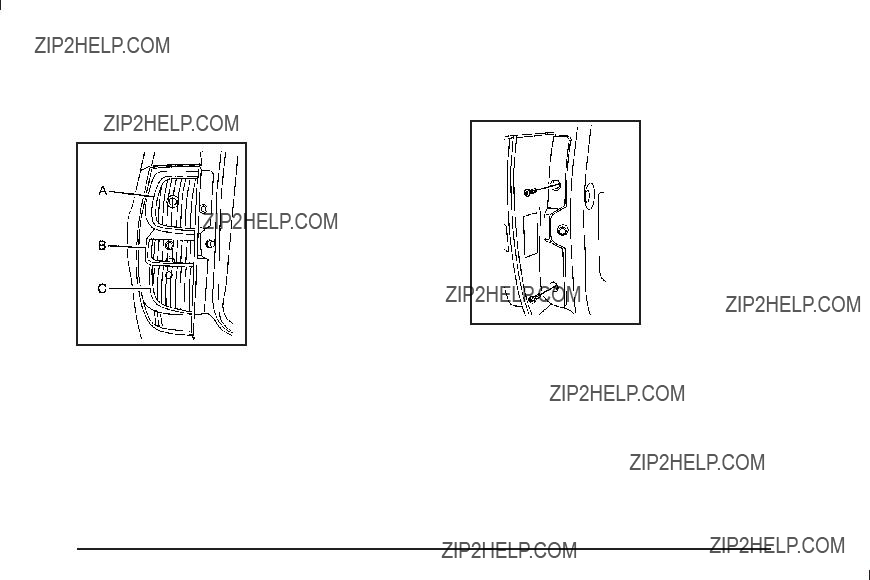
Installing the Third Row Seat
To install the seat, do the following:
1.Open the liftgate to access the rear of the vehicle.
2.Slide the front outboard seat wheels into the
track on the ???oor and roll the seat forward. The front latches should lock into place. If the latches do
not lock, try tilting the rear of the seat upward slightly.
3.Lower the rear of the seat and push down on the seat to engage the rear ???oor latches.
{CAUTION:
A seat that is not locked into place properly can move around in a collision or sudden stop. People in the vehicle could be injured. Be sure to lock the seat into place properly when installing it.
4.Push and pull on the seat to make sure it is locked into place. The seatback cannot be raised to the upright position unless the seat is secured to
the ???oor.
5.Pull up on the seatback until it locks into the upright position.
{ CAUTION:
If either seatback is not locked, it could move forward in a sudden stop or crash. That could cause injury to the person sitting there. Always push and pull on the seatbacks to be sure they are locked.
6.Push and pull on the seatback to make sure it is locked.
{ CAUTION:
A safety belt that is improperly routed, not properly attached, or twisted will not provide the protection needed in a crash. The person wearing the belt could be seriously injured. After raising the rear seatback, always check to be sure that the safety belts are properly routed and attached, and are not twisted.
7.Make sure the safety belts are returned to the original position over the seatbacks.
Safety Belts
Safety Belts: They Are for Everyone
This section of the manual describes how to use safety belts properly. It also describes some things not to do with safety belts.
{ CAUTION:
Do not let anyone ride where a safety belt cannot be worn properly. In a crash, if you or your passenger(s) are not wearing safety belts, the injuries can be much worse. You can hit things inside the vehicle harder or be ejected from the vehicle. You and your passenger(s) can be seriously injured or killed. In the same crash, you might not be, if you are buckled up. Always fasten your safety belt, and check that your passenger(s) are restrained properly too.
{ CAUTION:
It is extremely dangerous to ride in a cargo area, inside or outside of a vehicle. In a collision, people riding in these areas are more likely to be seriously injured or killed. Do not allow people to ride in any area of your vehicle that is not equipped with seats and safety belts. Be sure everyone in your vehicle is in a seat and using a safety belt properly.
This vehicle has indicators as a reminder to buckle the safety belts. See Safety Belt Reminders on page
In most states and in all Canadian provinces, the law requires wearing safety belts. Here is why:
You never know if you will be in a crash. If you do have a crash, you do not know if it will be a serious one.
A few crashes are mild, and some crashes can be so serious that even buckled up, a person would not survive. But most crashes are in between. In many of them, people who buckle up can survive and sometimes walk away. Without safety belts, they could have been badly hurt or killed.
After more than 40 years of safety belts in vehicles, the facts are clear. In most crashes buckling up does matter... a lot!
Why Safety Belts Work
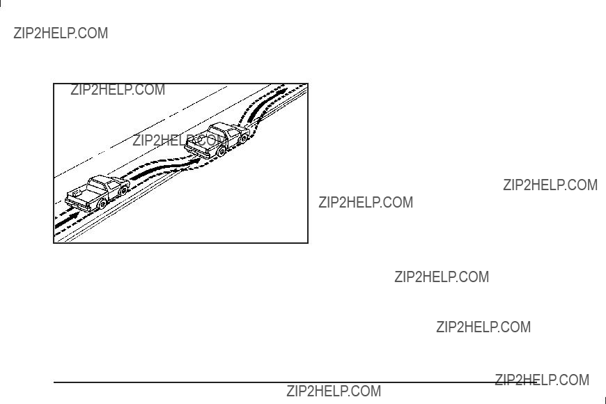
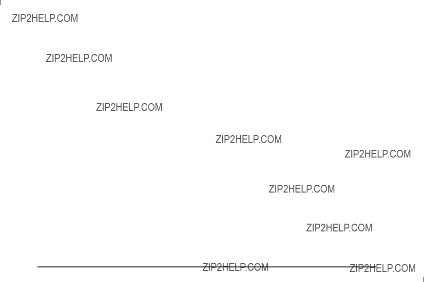
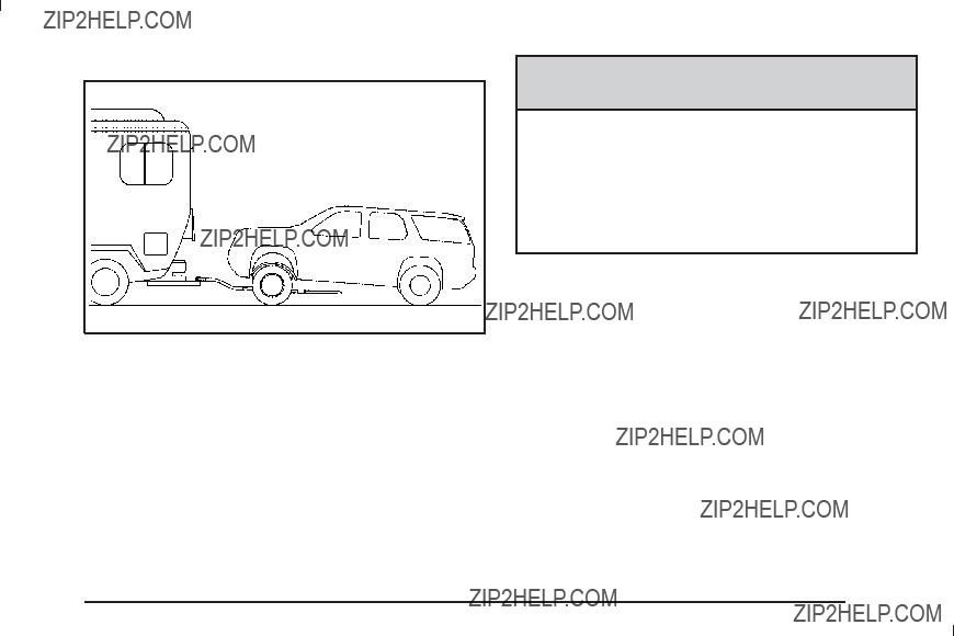
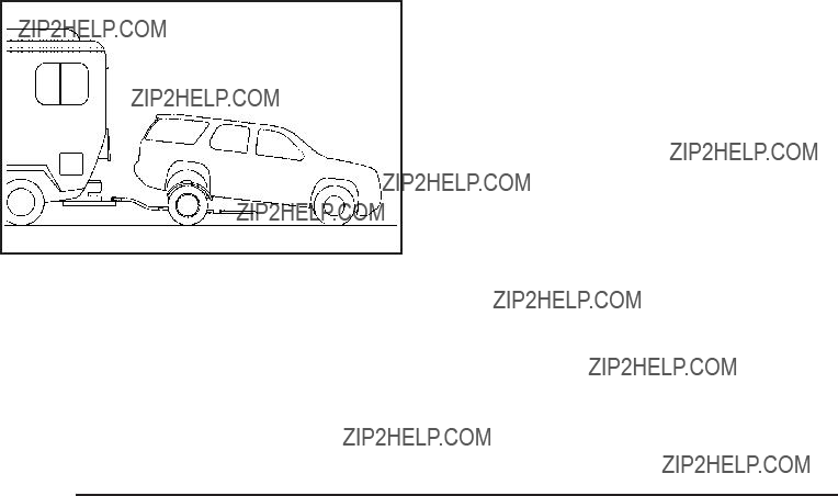
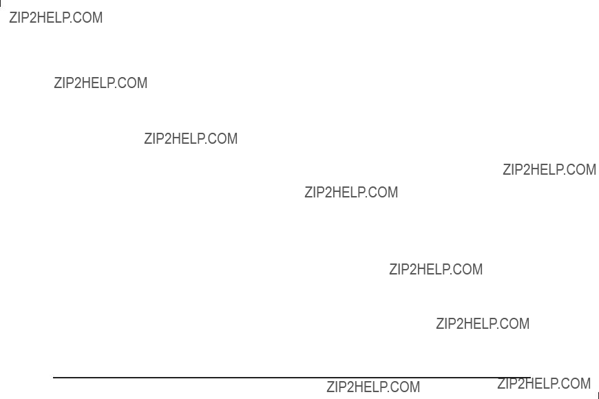
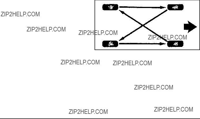
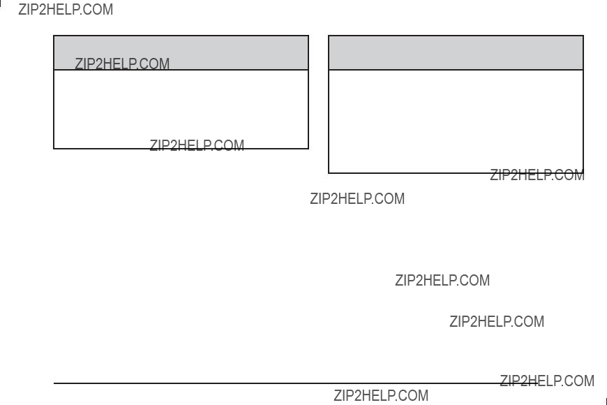
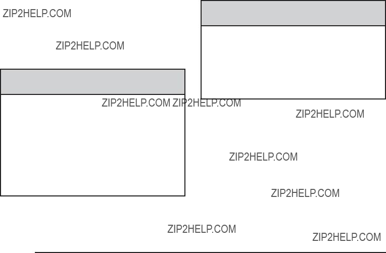
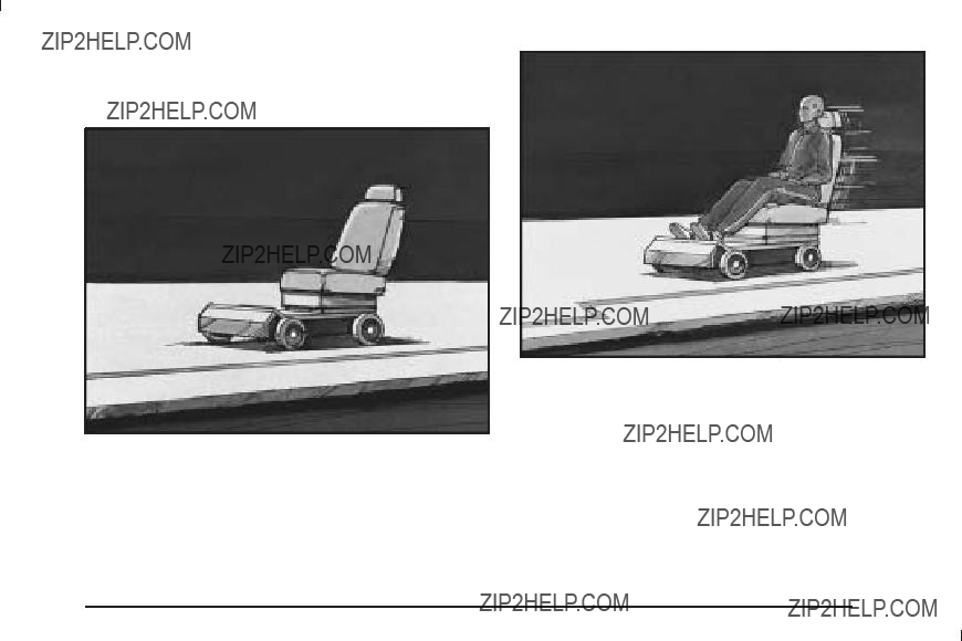
When you ride in or on anything, you go as fast as it goes.
Put someone on it.
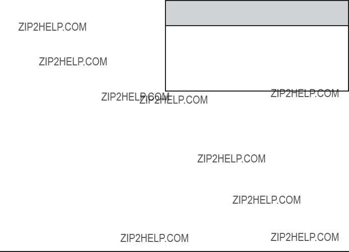
Take the simplest vehicle. Suppose it is just a seat on wheels.

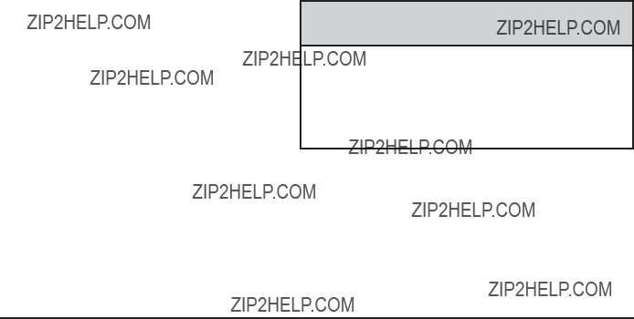
Get it up to speed. Then stop the vehicle. The rider does not stop.
The person keeps going until stopped by something. In
a real vehicle, it could be the windshield...

Questions and Answers About Safety
Belts
Q:
A: You could be ??? whether you are wearing a safety belt or not. But your chance of being conscious during and after an accident, so you can unbuckle and get out, is much greater if you are belted.
And you can unbuckle a safety belt, even if you are upside down.
Q:
A: Airbags are supplemental systems only; so they work with safety belts ??? not instead of them. Whether or not an airbag is provided, all occupants still have to buckle up to get the most protection. That is true not only in frontal collisions, but especially in side and other collisions.
Q: If I am a good driver, and I never drive far from home, why should I wear safety belts?
A: You may be an excellent driver, but if you are in a crash ??? even one that is not your fault ??? you and your passenger(s) can be hurt. Being a good
driver does not protect you from things beyond your control, such as bad drivers.
Most accidents occur within 25 miles (40 km) of home. And the greatest number of serious injuries and deaths occur at speeds of less than 40 mph (65 km/h).
Safety belts are for everyone.
How to Wear Safety Belts Properly
This section is only for people of adult size.
Be aware that there are special things to know about safety belts and children. And there are different rules for smaller children and infants. If a child will be
riding in the vehicle, see Older Children on page
Infants and Young Children on page
It is very important for all occupants to buckle up. Statistics show that unbelted people are hurt more often in crashes than those who are wearing safety belts.
Occupants who are not buckled up can be thrown out of the vehicle in a crash. And they can strike others in
the vehicle who are wearing safety belts.
First, before you or your passenger(s) wear a safety belt, there is important information you should know.
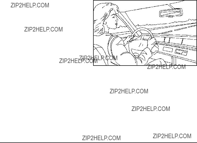
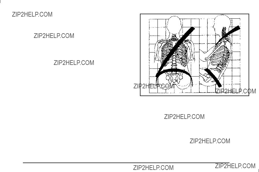
Sit up straight and always keep your feet on the ???oor in front of you. The lap part of the belt should be worn low and snug on the hips, just touching the thighs. In a crash, this applies force to the strong pelvic bones and you would be less likely to slide under the lap belt. If you slid under it, the belt would apply force on your abdomen. This could cause serious or even fatal injuries. The shoulder belt should go over the shoulder and across the chest. These parts of the body are best able to take belt restraining forces.
The shoulder belt locks if there is a sudden stop or crash.
Q: What is wrong with this?
A: The shoulder belt is too loose. It will not give as much protection this way.
{ CAUTION:
You can be seriously hurt if your shoulder belt is too loose. In a crash, you would move forward too much, which could increase injury. The shoulder belt should ???t snugly against your body.

Q: What is wrong with this?
A: The lap belt is too loose. It will not give nearly as much protection this way.
{ CAUTION:
You can be seriously hurt if your lap belt is too loose. In a crash, you could slide under the lap belt and apply force on your abdomen. This could cause serious or even fatal injuries. The lap belt should be worn low and snug on the hips, just touching the thighs.
Q: What is wrong with this?
A: The belt is buckled in the wrong buckle.
{ CAUTION:
You can be seriously injured if your belt is buckled in the wrong place like this. In a crash, the belt would go up over your abdomen. The belt forces would be there, not on the pelvic bones. This could cause serious internal injuries. Always buckle your belt into the buckle nearest you.
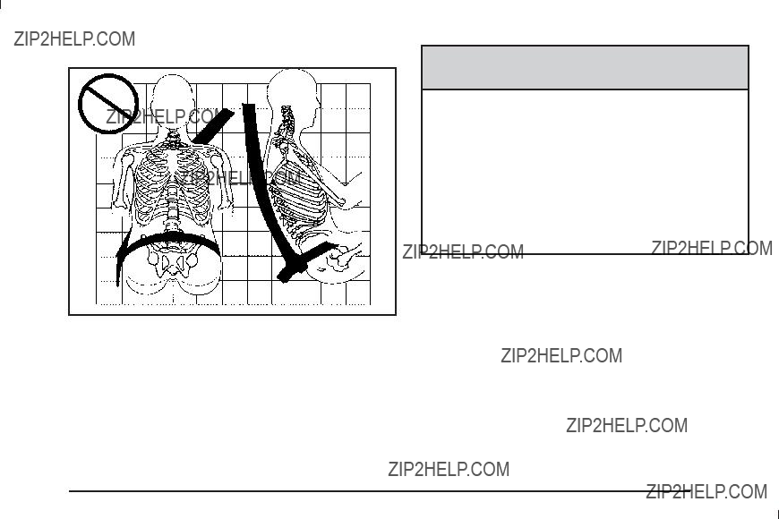
Q: What is wrong with this?
{ CAUTION:
You can be seriously injured if your belt goes over an armrest like this. The belt would be much too high. In a crash, you can slide under the belt. The belt force would then be applied on the abdomen, not on the pelvic bones, and that could cause serious or fatal injuries. Be sure the belt goes under the armrests.
A: The belt is over an armrest.

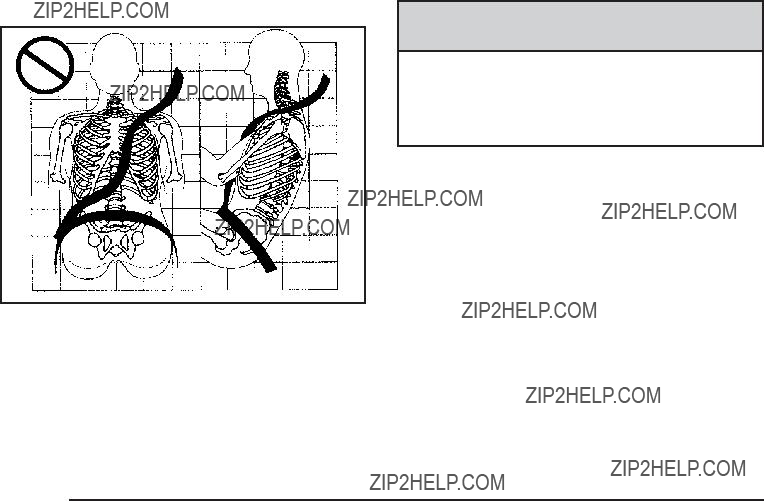
Q: What is wrong with this?
A: The shoulder belt is worn under the arm. It should be worn over the shoulder at all times.
{ CAUTION:
You can be seriously injured if you wear the shoulder belt under your arm. In a crash, your body would move too far forward, which would increase the chance of head and neck injury. Also, the belt would apply too much force to the ribs, which are not as strong as shoulder bones. You could also severely injure internal organs like your liver or spleen. The shoulder belt should go over the shoulder and across the chest.
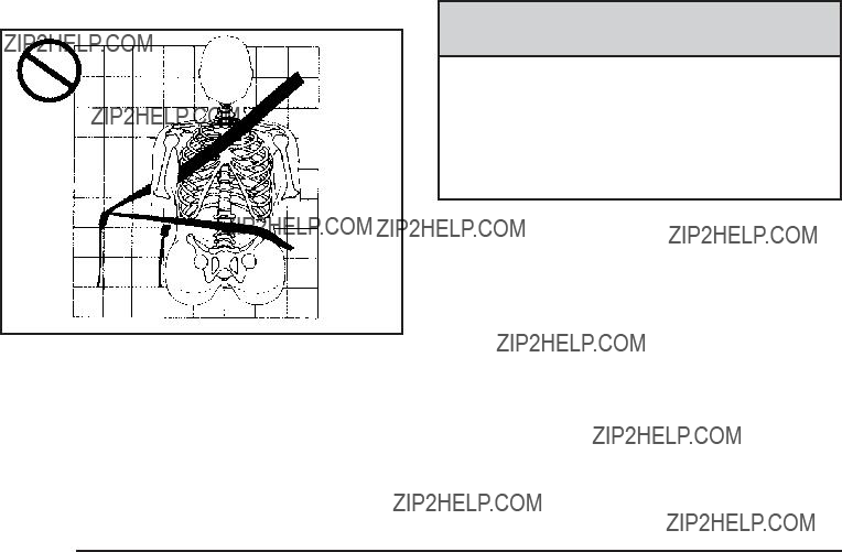
Q: What is wrong with this?
{ CAUTION:
You can be seriously injured by not wearing the
A: The belt is behind the body.

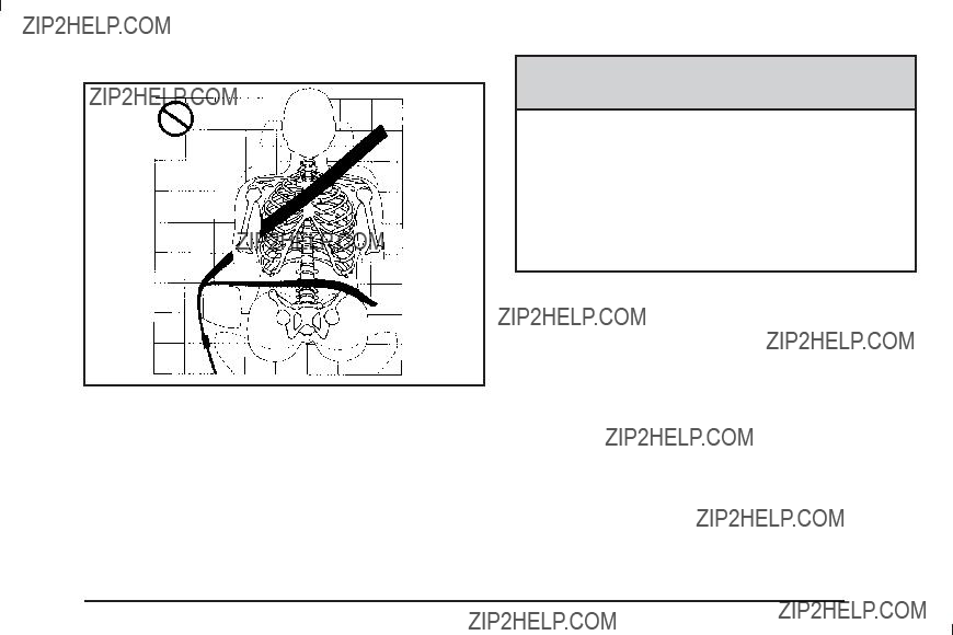
Q: What is wrong with this?
A: The belt is twisted across the body.
{ CAUTION:
You can be seriously injured by a twisted belt. In a crash, you would not have the full width of the belt to spread impact forces. If a belt is twisted, make it straight so it can work properly, or ask your dealer/retailer to ???x it.
All seating positions in the vehicle have a
page
The
Use the following pictures to determine the latch plate style:
Cinching Latch Plate
The following instructions explain how to wear a
1.Adjust the seat, if the seat is adjustable, so you can sit up straight. To see how, see ???Seats??? in the Index.
2.Pick up the latch plate and pull the belt across you. Do not let it get twisted.
The
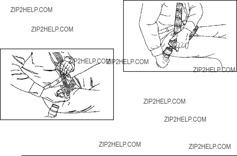
If the shoulder portion of a passenger belt with a
If this happens, let the belt go back all the way and start again.
Engaging the child restraint locking feature in the right front seating position may affect the passenger sensing system. See Passenger Sensing System on page
If the belt stops before it reaches the buckle, for
it can be buckled.
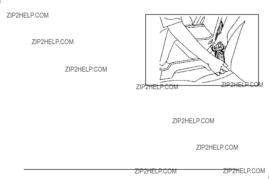
3.Push the latch plate into the buckle until it clicks. If you ???nd that the latch plate will not go fully into the buckle, see if you are using the correct buckle.
Pull up on the latch plate to make sure it is secure. If the belt is not long enough, see Safety Belt Extender on page
Position the release button on the buckle so that the safety belt could be quickly unbuckled if necessary.

4.If equipped with a shoulder belt height adjuster, move it to the height that is right for you. See ???Shoulder Belt Height Adjustment??? later in this section for instructions on use and important safety information.
5.To make the lap part tight, pull up on the shoulder belt.
It may be necessary to pull stitching on the safety belt through the latch plate to fully tighten the
lap belt on smaller occupants.
To unlatch the belt, push the button on the buckle. The belt should return to its stowed position.
Before a door is closed, be sure the safety belt is out of the way. If a door is slammed against a safety belt, damage can occur to both the belt and the vehicle.

Shoulder Belt Height Adjuster
The vehicle has a shoulder belt height adjuster for the driver and right front passenger positions.
Adjust the height so that the shoulder portion of the belt is centered on the shoulder. The belt should be away from the face and neck, but not falling off the shoulder. Improper shoulder belt height adjustment could
reduce the effectiveness of the safety belt in a crash.
Squeeze the buttons (A) on the sides of the height adjuster and move the height adjuster to the desired position.
The adjuster can be moved up just by pushing up on the shoulder belt guide.
After the adjuster is set to the desired position, try to move it down without squeezing the buttons to make sure it has locked into position.
Safety Belt Pretensioners
This vehicle has safety belt pretensioners for front outboard occupants. Although the safety belt pretensioners cannot be seen, they are part of the safety belt assembly. They can help tighten the safety belts during the early stages of a moderate to severe frontal, near frontal, or rear crash if the threshold conditions for pretensioner activation are met. And, if the vehicle has side impact airbags, safety belt pretensioners can help tighten the safety belts in a side crash or a rollover event.
Pretensioners work only once. If the pretensioners activate in a crash, they will need to be replaced, and probably other new parts for the vehicle???s safety
belt system. See Replacing Restraint System Parts After a Crash on page
Rear Safety Belt Comfort Guides
Rear shoulder belt comfort guides may provide added safety belt comfort for older children who have outgrown booster seats and for some adults. When installed on a shoulder belt, the comfort guide positions the belt away from the neck and head.
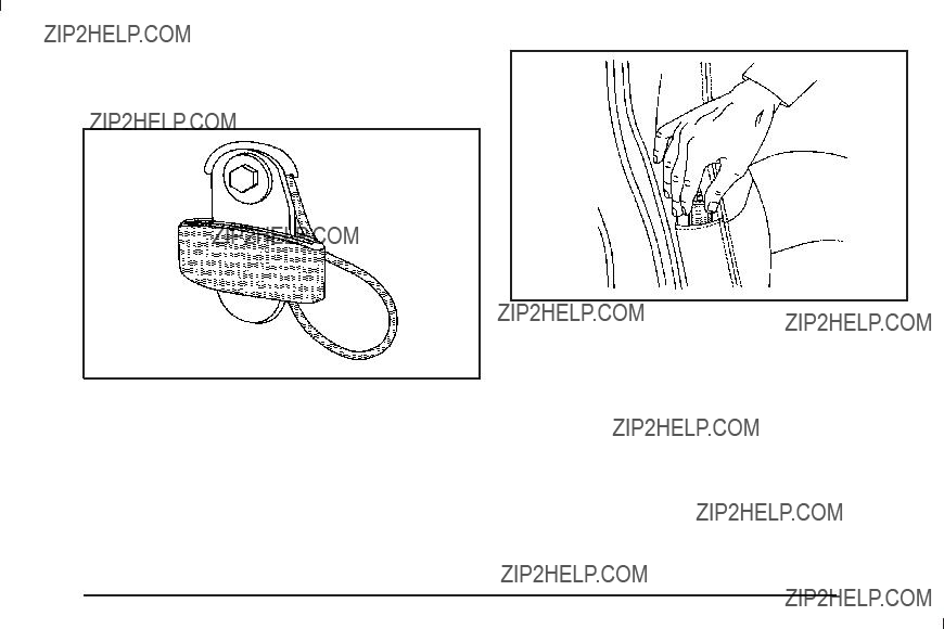
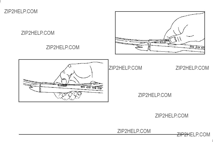
There is one guide for each outside passenger position in the second row seat and the third row, if the vehicle has one. Here is how to install a comfort guide to the safety belt:
Third Row
If your vehicle has a third row, remove the guide from its storage pocket on the side of the seat.
Second Row
1.For the second row, remove the guide from its storage clip on the interior body.
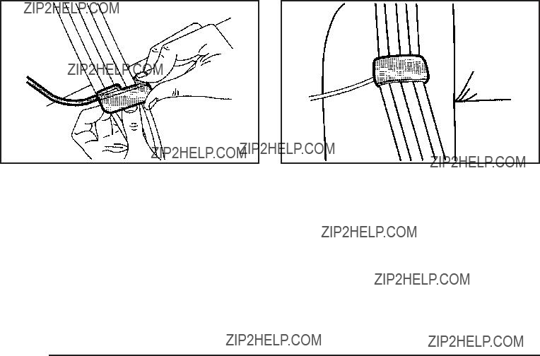
2.Place the guide over the belt, and insert the two edges of the belt into the slots of the guide.
3.Be sure that the belt is not twisted and it lies ???at. The elastic cord must be under the belt and the guide on top.

{ CAUTION:
A safety belt that is not properly worn may not provide the protection needed in a crash. The person wearing the belt could be seriously injured. The shoulder belt should go over the shoulder and across the chest. These parts of the body are best able to take belt restraining forces.
4. Buckle, position, and release the safety belt as described previously in this section. Make sure that the shoulder belt crosses the shoulder.
To remove and store the comfort guide, squeeze the belt edges together so that the safety belt can be removed from the guide. Slide the guide into its storage clip on the interior body or storage pocket on the
side of the seat.
Safety Belt Use During Pregnancy
Safety belts work for everyone, including pregnant women. Like all occupants, they are more likely to be seriously injured if they do not wear safety belts.
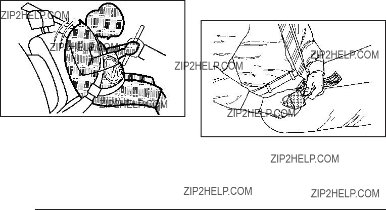
A pregnant woman should wear a
The best way to protect the fetus is to protect the mother. When a safety belt is worn properly, it is more likely that the fetus will not be hurt in a crash. For pregnant women, as for anyone, the key to making safety belts effective is wearing them properly.
Lap Belt
This part is only for the lap belt. To learn how to wear a
You vehicle may have a center seating position. When you sit in the center front seating position, you have a lap safety belt, which has no retractor.
To make the belt longer, tilt the latch plate and pull it along the belt.
Buckle, position and release it the same way as the lap part of a

To make the belt shorter, pull its free end as shown until the belt is snug.
If the belt is not long enough, see Safety Belt Extender on page
Make sure the release button on the buckle is positioned so you would be able to unbuckle the safety belt quickly if necessary.
If you ???nd that the latch plate will not go fully into the buckle, see if you are using the correct buckle. Be sure that the latch plate clicks when inserted into the buckle.
Safety Belt Extender
If the vehicle???s safety belt will fasten around you, you should use it.
But if a safety belt is not long enough, your dealer/retailer will order you an extender. When you go in to order it, take the heaviest coat you will wear,
so the extender will be long enough for you. To help avoid personal injury, do not let someone else use it, and use it only for the seat it is made to ???t. The
extender has been designed for adults. Never use it for securing child seats. To wear it, attach it to the
regular safety belt. For more information, see the instruction sheet that comes with the extender.

Child Restraints
Older Children
Older children who have outgrown booster seats should wear the vehicle???s safety belts.
The manufacturer???s instructions that come with the booster seat, state the weight and height limitations for that booster. Use a booster seat with a
???Sit all the way back on the seat. Do the knees bend at the seat edge? If yes, continue. If no, return to the booster seat.
???Buckle the
???Does the lap belt ???t low and snug on the hips, touching the thighs? If yes, continue. If no, return to the booster seat.
???Can proper safety belt ???t be maintained for length of trip? If yes, continue. If no, return to the booster seat.
If you have the choice, a child should sit in a position with a
Q: What is the proper way to wear safety belts?
A: An older child should wear a
Also see ???Rear Safety Belt Comfort Guides??? under
According to accident statistics, children and infants are safer when properly restrained in the rear seating positions than in the front seating positions.
In a crash, children who are not buckled up can strike other people who are buckled up, or can be thrown out of the vehicle. Older children need to use safety belts properly.
{ CAUTION:
Never do this.
Never allow two children to wear the same safety belt. The safety belt can not properly spread the impact forces. In a crash, the two children can be crushed together and seriously injured. A safety belt must be used by only one person at a time.

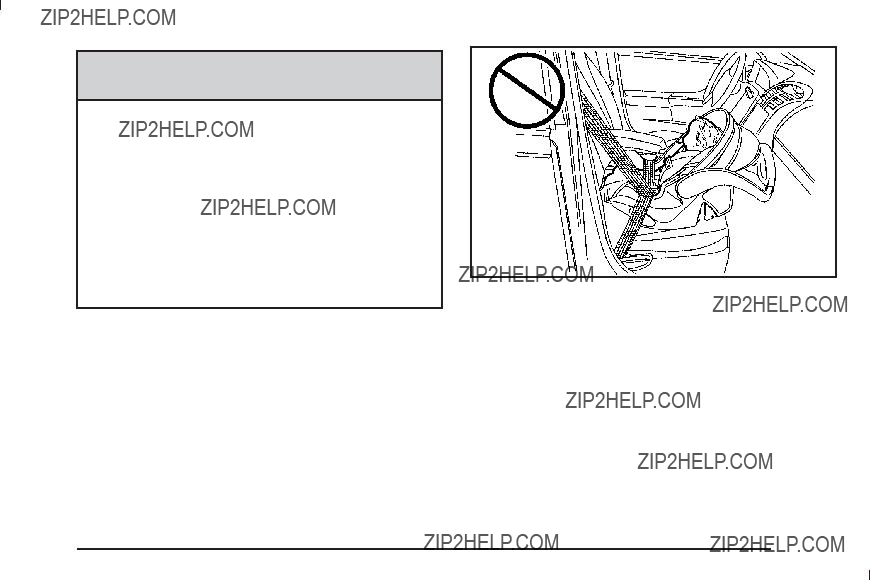
{ CAUTION:
Never do this.
Never allow a child to wear the safety belt with the shoulder belt behind their back. A child can be seriously injured by not wearing the

Infants and Young Children
Everyone in a vehicle needs protection! This includes infants and all other children. Neither the distance traveled nor the age and size of the traveler changes the need, for everyone, to use safety restraints. In fact, the law in every state in the United States and in every Canadian province says children up to some age must be restrained while in a vehicle.
{ CAUTION:
Children can be seriously injured or strangled if a shoulder belt is wrapped around their neck and the safety belt continues to tighten. Never leave children unattended in a vehicle and never allow children to play with the safety belts.
Airbags plus
its airbag system is designed for them. Every time infants and young children ride in vehicles, they should have the protection provided by appropriate child restraints.
Children who are not restrained properly can strike other people, or can be thrown out of the vehicle.
{ CAUTION:
Never do this.
Never hold an infant or a child while riding in a vehicle. Due to crash forces, an infant or a child will become so heavy it is not possible to hold it during a crash. For example, in a crash at only 40 km/h (25 mph), a 5.5 kg (12 lb) infant will suddenly become a 110 kg (240 lb) force on a person???s arms. An infant should be secured in an appropriate restraint.
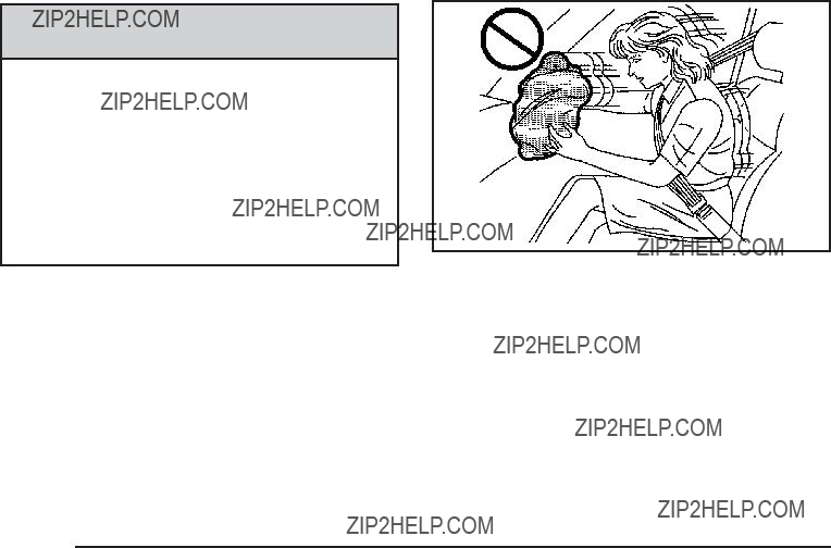
{ CAUTION:
Never do this.
Children who are up against, or very close to, any airbag when it in???ates can be seriously injured or killed. Never put a

Q: What are the different types of
A:
into consideration not only the child???s weight, height, and age but also whether or not the restraint will be compatible with the motor vehicle in which it will be used.
For most basic types of child restraints, there are many different models available. When purchasing a child restraint, be sure it is designed to be used
in a motor vehicle. If it is, the restraint will have a label saying that it meets federal motor vehicle safety standards.
The restraint manufacturer???s instructions that come with the restraint state the weight and height limitations for a particular child restraint. In addition, there are many kinds of restraints available for children with special needs.
{ CAUTION:
To reduce the risk of neck and head injury during a crash, infants need complete support. This is because an infant???s neck is not fully developed and its head weighs so much compared with the rest of its body. In a crash, an infant in a
{ CAUTION:
A young child???s hip bones are still so small that the vehicle???s regular safety belt may not remain low on the hip bones, as it should. Instead, it may settle up around the child???s abdomen. In a crash, the belt would apply force on a body area that is unprotected by any bony structure. This alone could cause serious or fatal injuries. To reduce the risk of serious or fatal injuries during a crash, young children should always be secured in appropriate child restraints.
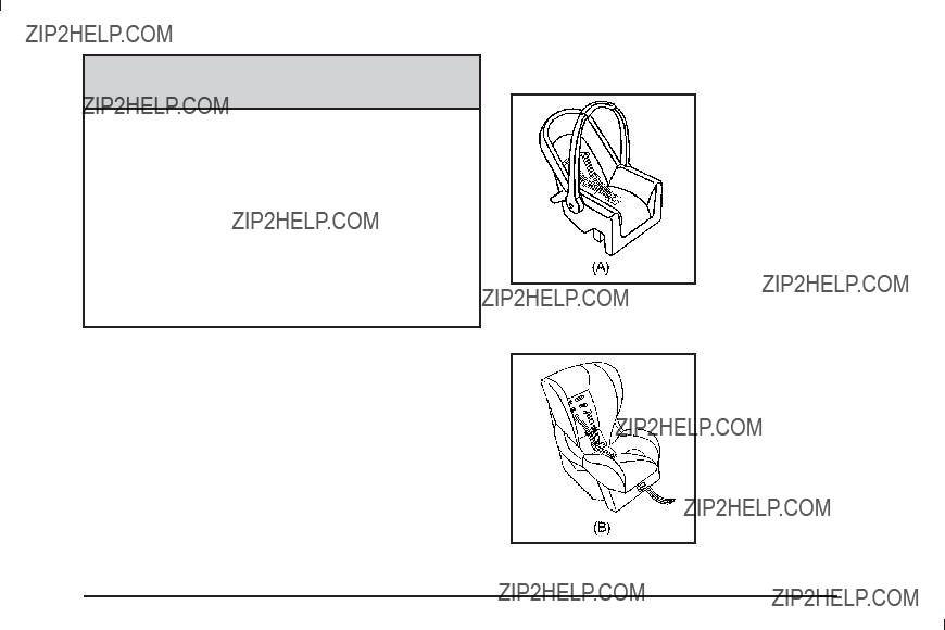
Child Restraint Systems
A
seat (A) provides restraint with the seating surface against the back of
the infant.
The harness system holds the infant in place and, in a crash, acts to keep the infant positioned in the restraint.
A

A booster seat
Securing an
the Vehicle
{ CAUTION:
A child can be seriously injured or killed in a crash if the child restraint is not properly secured in the vehicle. Secure the child restraint properly in the vehicle using the vehicle???s safety belt or LATCH system, following the instructions that came with that child restraint and the instructions in this manual.
To help reduce the chance of injury, the child restraint must be secured in the vehicle. Child restraint systems must be secured in vehicle seats by lap belts or the lap belt portion of a

When securing an
Keep in mind that an unsecured child restraint can move around in a collision or sudden stop and injure people in the vehicle. Be sure to properly secure
any child restraint in the vehicle ??? even when no child is in it.
Securing the Child Within the Child
Restraint
{ CAUTION:
A child can be seriously injured or killed in a crash if the child is not properly secured in the child restraint. Secure the child properly following the instructions that came with that child restraint.
Where to Put the Restraint
According to accident statistics, children and infants are safer when properly restrained in a child restraint system or infant restraint system secured in a rear seating position.
We recommend that children and child restraints be secured in a rear seat, including: an infant or a
child riding in a
a booster seat; and children, who are large enough, using safety belts.
A label on your sun visor says, ???Never put a
{ CAUTION:
A child in a
Even if the passenger sensing system has turned off the right front passenger frontal airbag, no system is
CAUTION: (Continued)
CAUTION: (Continued)
Secure
See Passenger Sensing System on page
{ CAUTION:
A child in a child restraint in the center front seat can be badly injured or killed by the frontal airbags if they in???ate. Never secure a child restraint in the center front seat. It is always better to secure a child restraint in a rear seat.
Do not use child restraints in the center front seat position.
When securing a child restraint in a rear seating position, study the instructions that came with your child restraint to make sure it is compatible with this vehicle.
Wherever a child restraint is installed, be sure to secure the child restraint properly.
Keep in mind that an unsecured child restraint can move around in a collision or sudden stop and injure people in the vehicle. Be sure to properly secure any child restraint in your vehicle ??? even when no child is in it.
Lower Anchors and Tethers for Children (LATCH)
The LATCH system holds a child restraint during driving or in a crash. This system is designed to make installation of a child restraint easier. The LATCH system uses anchors in the vehicle and attachments on the child restraint that are made for use with the LATCH system.
Make sure that a
the child restraint. A child restraint must never be attached using only the top tether and anchor.
In order to use the LATCH system in your vehicle, you need a child restraint that has LATCH attachments. The child restraint manufacturer will provide you
with instructions on how to use the child restraint and its attachments. The following explains how to attach a child restraint with these attachments in your vehicle.
Not all vehicle seating positions or child restraints have lower anchors and attachments or top tether anchors and attachments.
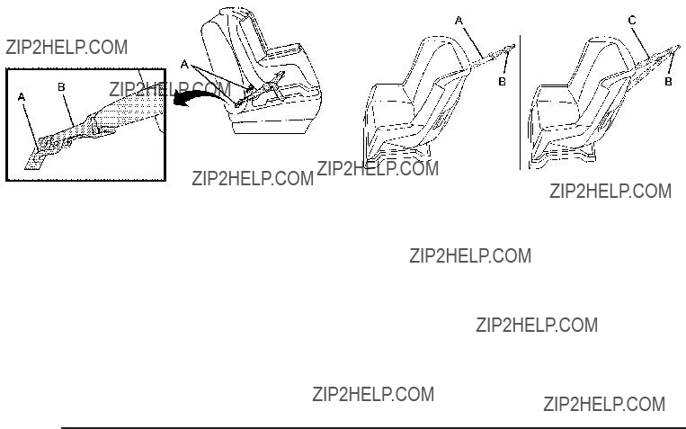
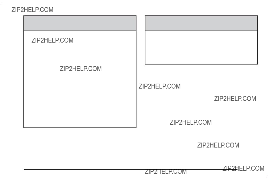
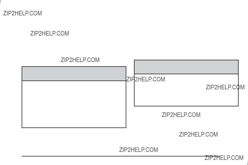
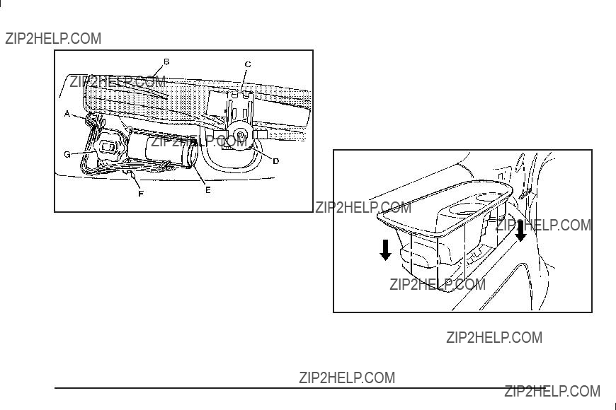
Lower anchors (A) are metal bars built into the vehicle. There are two lower anchors for each LATCH seating position that will accommodate a child restraint with lower attachments (B).
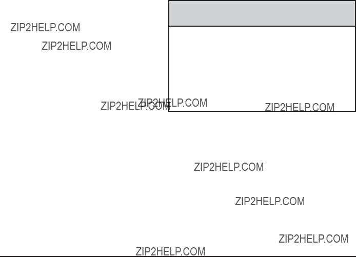
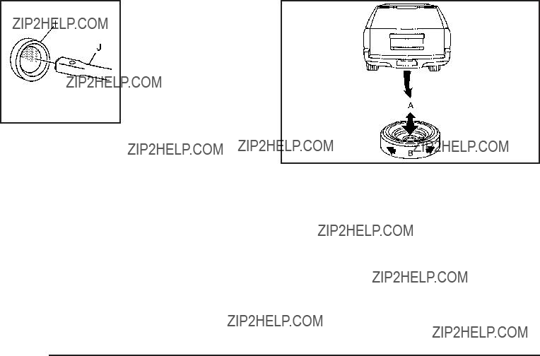
A top tether (A, C) anchors the top of the child restraint to the vehicle. A top tether anchor is built into the vehicle. The top tether attachment (B) on the child restraint connects to the top tether anchor in the vehicle in order to reduce the forward movement and rotation of the child restraint during driving or in a crash.
Your child restraint may have a single tether (A) or a dual tether (C). Either will have a single attachment (B) to secure the top tether to the anchor.
Some child restraints with top tethers are designed for use with or without the top tether being attached. Others require the top tether always to be attached. In Canada, the law requires that
If the child restraint does not have a top tether, one can be obtained, in kit form, for many child restraints. Ask the child restraint manufacturer whether or not a kit
is available.
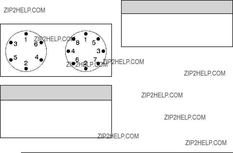
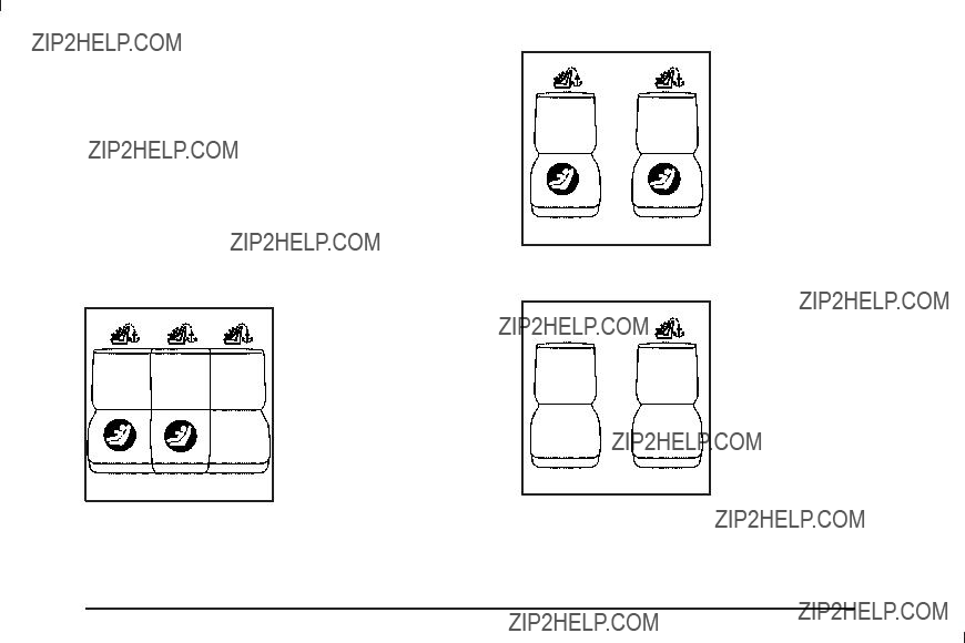
j (Lower Anchor): Seating positions with two lower anchors.
i (Top Tether Anchor): Seating positions with top tether anchors.
j (Lower Anchor): Seating positions with two lower anchors.
i (Top Tether Anchor): Seating positions with top tether anchors.
i (Top Tether Anchor): Seating positions with top tether anchors.

i (Top Tether Anchor): Seating positions with top tether anchors. There is one top tether anchor that can be used for either the third row center or driver side seating position but not both at the same time.
Third Row ??? Three
Passenger
For models with a three passenger third row seat, see the information following for installing a child restraint with a top tether in the third row, if your vehicle has one. Never install two top tethers using the same top
tether anchor.
For models with 60/40 second row seating, the rear right side passenger and center seating positions have exposed metal anchors located in the crease between the seatback and the seat cushion.
For models with second row bucket seats, both rear seating positions have exposed metal anchors located in the crease between the seatback and the seat cushion.
Second Row Seat ??? Bucket
For models with bucket second row seating, the top tether anchors are located at the bottom rear of the seat cushion for each seating position in the second row.
Be sure to use an anchor located on the same side of the vehicle as the seating position where the child restraint will be placed.

For models with 60/40 second row seating, the top tether anchors are located at the bottom rear of the seat cushion for each seating position in the second row.
Be sure to use an anchor located on the same side of the vehicle as the seating position where the child restraint will be placed.
For vehicles with a two passenger third row seat, there is one top tether anchor located at the bottom rear
of the seat cushion that can be used for the rear driver side seating position in the third row. Never install
two top tethers using the same top tether anchor.
For vehicles with a three passenger third row seat, there is one top tether anchor located at the bottom rear of the seat cushion that can be used for either the third row center or driver side seating position. Never install
two top tethers using the same top tether anchor.

Do not secure a child restraint in a position without a top tether anchor if a national or local law requires that the top tether be attached, or if the instructions that come with the child restraint say that the top tether must be attached.
According to accident statistics, children and infants are safer when properly restrained in a child restraint system or infant restraint system secured in a rear seating position. See Where to Put the Restraint
on page
Securing a Child Restraint Designed for the LATCH System
{ CAUTION:
If a
{ CAUTION:
Do not attach more than one child restraint to a single anchor. Attaching more than one child restraint to a single anchor could cause the anchor or attachment to come loose or even break during a crash. A child or others could be injured. To reduce the risk of serious or fatal injuries during a crash, attach only one child restraint per anchor.
{ CAUTION:
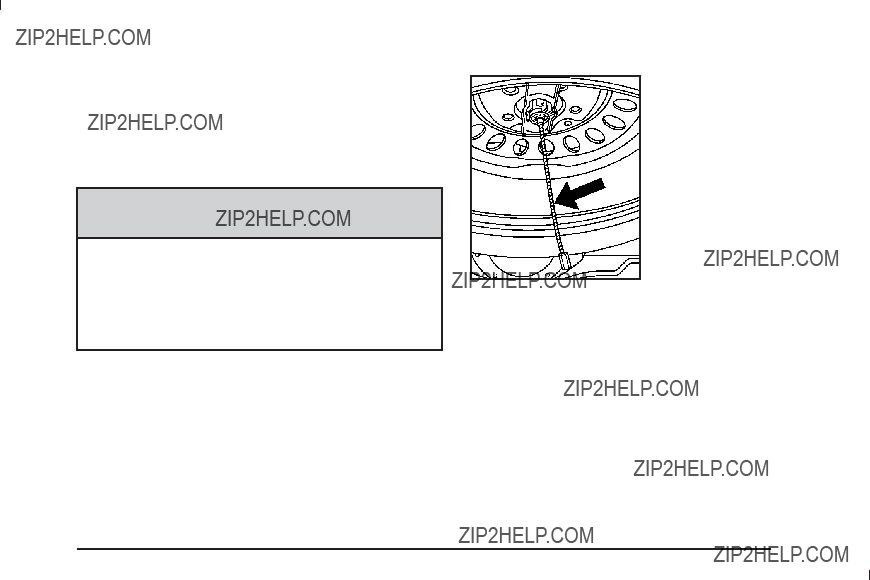
Children can be seriously injured or strangled if a shoulder belt is wrapped around their neck and the safety belt continues to tighten. Buckle any unused safety belts behind the child restraint so children cannot reach them. Pull the shoulder belt all the way out of the retractor to set the lock, if your vehicle has one, after the child restraint has been installed.
Notice: Do not let the LATCH attachments rub against the vehicle???s safety belts. This may damage these parts. If necessary, move buckled safety belts to avoid rubbing the LATCH attachments.
Do not fold the empty rear seat with a safety belt buckled. This could damage the safety belt or
the seat. Unbuckle and return the safety belt to its stowed position, before folding the seat.
1.Attach and tighten the lower attachments to the lower anchors. If the child restraint does not have lower attachments or the desired seating position does not have lower anchors, secure the child restraint with the top tether and the safety belts. Refer to your child restraint manufacturer instructions and the instructions in this manual.
1.1.Find the lower anchors for the desired seating position.
1.2.Put the child restraint on the seat.
1.3.Attach and tighten the lower attachments on the child restraint to the lower anchors.
2.If the child restraint manufacturer recommends that the top tether be attached, attach and tighten the top tether to the top tether anchor, if the vehicle has one. Refer to the child restraint instructions and
the following steps:
2.1.Find the top tether anchor.
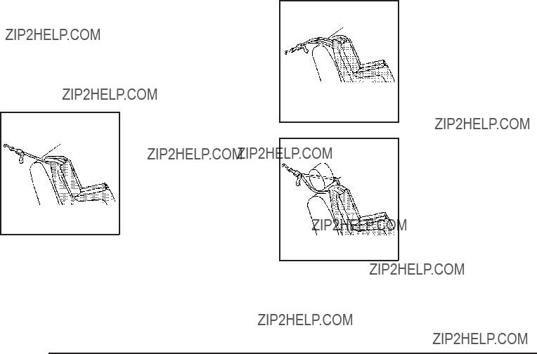
2.2.Route, attach and tighten the top tether according to your child restraint instructions and the following instructions:
If the position you are using does not have a headrest or head restraint and you are using a single tether, route the tether over the seatback.
If the position you are using does not have a headrest or head restraint and you are using a
dual tether, route the tether over the seatback.
If the position you are using has an adjustable headrest or head restraint and you are using a
dual tether, route the tether around the headrest or head restraint.
If the position you are using has an adjustable headrest or head restraint and you are using a single tether, raise the headrest or head restraint and route the tether
under the headrest or head restraint and in between the headrest or head restraint posts.
3.Push and pull the child restraint in different directions to be sure it is secure.
Securing a Child Restraint in a Rear
Seat Position
When securing a child restraint in a rear seating position, study the instructions that came with the child restraint to make sure it is compatible with this vehicle.
If the child restraint has the LATCH system, see Lower Anchors and Tethers for Children (LATCH) on page
Do not secure a child seat in a position without a top tether anchor if a national or local law requires that the top tether be anchored, or if the instructions that
come with the child restraint say that the top strap must be anchored.
In Canada, the law requires that
If the child restraint does not have the LATCH system, you will be using the safety belt to secure the child restraint in this position. Be sure to follow the instructions that came with the child restraint. Secure the child in the child restraint when and as the instructions say.

If more than one child restraint needs to be installed in the rear seat, be sure to read Where to Put the Restraint on page
The vehicle???s
Use the following pictures to determine the latch plate style:
Cinching Latch Plate
1.Put the child restraint on the seat.
2.Pick up the latch plate, and run the lap and shoulder portions of the vehicle???s safety belt through or around the restraint. The child restraint instructions will show you how.
For third row seating positions, with cinching latch plates, tilt the latch plate to adjust the belt if needed.
3.Push the latch plate into the buckle until it clicks.
Position the release button on the buckle so that the safety belt could be quickly unbuckled if necessary.
4.For passenger seating positions with a
set the lock. When installing a child restraint using a
5.To tighten the belt, push down on the child restraint, pull the shoulder portion of the belt to tighten the lap portion of the belt and feed the shoulder
belt back into the retractor. When installing a
6.If the child restraint has a top tether, follow the child restraint manufacturer???s instructions regarding the use of the top tether. See Lower Anchors and Tethers for Children (LATCH) on page
7.Push and pull the child restraint in different directions to be sure it is secure.
To remove the child restraint, unbuckle the vehicle safety belt and let it return to the stowed position. If the top tether is attached to a top tether anchor, disconnect it.
Securing a Child Restraint in the
Center Front Seat Position
{ CAUTION:
A child in a child restraint in the center front seat can be badly injured or killed by the frontal airbags if they in???ate. Never secure a child restraint in the center front seat. It is always better to secure a child restraint in a rear seat.
Do not use child restraints in the center front seat position.
Securing a Child Restraint in the
Right Front Seat Position
This vehicle has airbags. A rear seat is a safer place to secure a
In addition, the vehicle has a passenger sensing system which is designed to turn off the right front passenger frontal airbag under certain conditions. See Passenger Sensing System on page

A label on the sun visor says, ???Never put a
the
{ CAUTION:
A child in a
Even if the passenger sensing system has turned off the right front passenger frontal airbag, no system is
CAUTION: (Continued)
CAUTION: (Continued)
Secure
See Passenger Sensing System on page
If the child restraint has the LATCH system, see Lower Anchors and Tethers for Children (LATCH) on
page
top tether anchor locations.
Do not secure a child seat in a position without a top tether anchor if a national or local law requires that the top tether be anchored, or if the instructions that
come with the child restraint say that the top strap must be anchored.
In Canada, the law requires that
You will be using the
1.Move the seat as far back as it will go before securing the
When the passenger sensing system has turned off the right front passenger frontal airbag, the off indicator on the passenger airbag status indicator should light and stay lit when the vehicle is started. See Passenger Airbag Status Indicator on
page
2.Put the child restraint on the seat.
3.Pick up the latch plate, and run the lap and shoulder portions of the vehicle???s safety belt through or around the restraint. The child restraint instructions will show you how.
4.Push the latch plate into the buckle until it clicks.
Position the release button on the buckle so that the safety belt could be quickly unbuckled if necessary.
5.Pull the rest of the shoulder belt all the way out of the retractor to set the lock.
6.To tighten the belt, push down on the child restraint, pull the shoulder portion of the belt to tighten the lap portion of the belt and feed the shoulder
belt back into the retractor. When installing a
7.Push and pull the child restraint in different directions to be sure it is secure.
If the airbag is off, the off indicator in the passenger airbag status indicator will come on and stay on when the vehicle is started.
If a child restraint has been installed and the on indicator is lit, see ???If the On Indicator is Lit for a Child Restraint??? under Passenger Sensing System on
page
To remove the child restraint, unbuckle the vehicle safety belt and let it return to the stowed position.
Airbag System
The vehicle has the following airbags:
???A frontal airbag for the driver.
???A frontal airbag for the right front passenger.
The vehicle may have the following airbags:
???A
???A
???If your vehicle has a third row seat, it will have a third row
All of the airbags in the vehicle will have the word AIRBAG embossed in the trim or on an attached label near the deployment opening.
For frontal airbags, the word AIRBAG will appear on the middle part of the steering wheel for the driver and
on the instrument panel for the right front passenger.
With

Airbags are designed to supplement the protection provided by safety belts. Even though today???s airbags are also designed to help reduce the risk of injury
from the force of an in???ating bag, all airbags must in???ate very quickly to do their job.
Here are the most important things to know about the airbag system:
{ CAUTION:
You can be severely injured or killed in a crash if you are not wearing your safety belt ??? even if you have airbags. Airbags are designed to work with safety belts, but do not replace them. Also, airbags are not designed to deploy in every crash. In some crashes safety belts are your only restraint. See
When Should an Airbag In???ate? on page
Wearing your safety belt during a crash helps reduce your chance of hitting things inside the vehicle or being ejected from it. Airbags are ???supplemental restraints??? to the safety belts. Everyone in your vehicle should wear a safety belt properly ??? whether or not there is an airbag for that person.
{ CAUTION:
Airbags in???ate with great force, faster than the blink of an eye. Anyone who is up against, or very close to, any airbag when it in???ates can be seriously injured or killed. Do not sit unnecessarily close to the airbag, as you would be if you were sitting on the edge of your seat or leaning forward. Safety belts help keep you in position before and during a crash. Always wear your safety belt, even with airbags. The driver should sit as far back as possible while still maintaining control of the vehicle.
Occupants should not lean on or sleep against the door or side windows in seating positions with

{ CAUTION:
Children who are up against, or very close to, any airbag when it in???ates can be seriously injured or killed. Airbags plus
There is an airbag readiness light on the instrument panel cluster, which shows the airbag symbol.
The system checks the airbag electrical system for malfunctions. The light tells you if there is an electrical problem. See Airbag Readiness Light on page
Where Are the Airbags?
The driver???s frontal airbag is in the middle of the steering wheel.

The right front passenger???s frontal airbag is in the instrument panel on the passenger???s side.
Driver Side shown, Passenger Side similar
If your vehicle has
Driver Side shown, Passenger Side similar
If your vehicle has
{ CAUTION:
If something is between an occupant and an airbag, the airbag might not in???ate properly or it might force the object into that person causing severe injury or even death. The path of an in???ating airbag must be kept clear. Do not put anything between an occupant and an airbag, and do not attach or put anything on the steering wheel hub or on or near any other airbag covering.
Never secure anything to the roof of a vehicle with

When Should an Airbag In???ate?
Frontal airbags are designed to in???ate in moderate to severe frontal or
help restrain the occupants.
Whether your frontal airbags will or should deploy is not based on how fast your vehicle is traveling. It depends largely on what you hit, the direction of the impact,
and how quickly your vehicle slows down.
Frontal airbags may in???ate at different crash speeds. For example:
???If the vehicle hits a stationary object, the airbags could in???ate at a different crash speed than if the vehicle hits a moving object.
???If the vehicle hits an object that deforms, the airbags could in???ate at a different crash speed than if the vehicle hits an object does not deform.
???If the vehicle hits a narrow object (like a pole), the airbags could in???ate at a different crash speed than if the vehicle hits a wide object (like a wall).
???If the vehicle goes into an object at an angle, the airbags could in???ate at a different crash speed than if the vehicle goes straight into the object.
Thresholds can also vary with speci???c vehicle design.
Frontal airbags are not intended to in???ate during vehicle rollovers, rear impacts, or in many side impacts.
In addition, your vehicle has
For more severe frontal impacts, full deployment occurs.
Your vehicle has a seat position sensor which enables the sensing system to monitor the position of the driver???s seat. The seat position sensor provides information that is used to determine if the airbags should deploy at a reduced level or at full deployment.
Your vehicle may or may not have
a severe frontal impact.
In any particular crash, no one can say whether an airbag should have in???ated simply because of the damage to a vehicle or because of what the repair costs were. For frontal airbags, in???ation is determined by what the vehicle hits, the angle of the impact, and how quickly the vehicle slows down. For
What Makes an Airbag In???ate?
In a deployment event, the sensing system sends an electrical signal triggering a release of gas from the in???ator. Gas from the in???ator ???lls the airbag causing the bag to break out of the cover and deploy. The in???ator, the airbag, and related hardware are all part of the airbag module.
Frontal airbag modules are located inside the steering wheel and instrument panel. For vehicles with

How Does an Airbag Restrain?
In moderate to severe frontal or near frontal collisions, even belted occupants can contact the steering wheel or the instrument panel. In moderate to severe side collisions, even belted occupants can contact the inside of the vehicle.
Airbags supplement the protection provided by safety belts. Frontal airbags distribute the force of the impact more evenly over the occupant???s upper body, stopping the occupant more gradually.
the occupant???s upper body.
Rollover capable
But airbags would not help in many types of collisions, primarily because the occupant???s motion is not toward those airbags. See When Should an Airbag In???ate? on page
Airbags should never be regarded as anything more than a supplement to safety belts.
What Will You See After an Airbag
In???ates?
After the frontal airbags in???ate, they quickly de???ate, so quickly that some people may not even realize an airbag in???ated.
The parts of the airbag that come into contact with you may be warm, but not too hot to touch. There may be some smoke and dust coming from the vents in the de???ated airbags. Airbag in???ation does not prevent the driver from seeing out of the windshield or being able to steer the vehicle, nor does it prevent people from leaving the vehicle.
{ CAUTION:
When an airbag in???ates, there may be dust in the air. This dust could cause breathing problems for people with a history of asthma or other breathing trouble. To avoid this, everyone in the vehicle should get out as soon as it is safe to do so. If you have breathing problems but cannot get out of the vehicle after an airbag in???ates, then get fresh air by opening a window or a door. If you experience breathing problems following an airbag deployment, you should seek medical attention.
The vehicle has a feature that may automatically unlock the doors, turn the interior lamps on, and turn the hazard warning ???ashers on when the airbags in???ate. You can lock the doors, turn the interior lamps off, and turn the hazard warning ???ashers off by using the controls for those features.
In many crashes severe enough to in???ate the airbag, windshields are broken by vehicle deformation. Additional windshield breakage may also occur
from the right front passenger airbag.
???Airbags are designed to in???ate only once. After an airbag in???ates, you will need some new parts for the airbag system. If you do not get them, the airbag system will not be there to help protect you in another crash. A new system will include airbag modules and possibly other parts. The service manual for the vehicle covers the need to replace other parts.
???The vehicle has a crash sensing and diagnostic module which records information after a crash. See Vehicle Data Recording and Privacy on
page
???Let only quali???ed technicians work on the airbag systems. Improper service can mean that an airbag system will not work properly. See your dealer/retailer for service.

Passenger Sensing System
The vehicle has a passenger sensing system for the right front passenger position. The passenger airbag status indicator will be visible on the overhead console when the vehicle is started.
The words ON and OFF, or the symbol for on and off, will be visible during the system check. If you are
using remote start to start the vehicle from a distance, if equipped, you may not see the system check. When the system check is complete, either the word ON
or OFF, or the symbol for on or off, will be visible. See
Passenger Airbag Status Indicator on page
The passenger sensing system will turn off the right front passenger frontal airbag under certain conditions. The driver airbag and the
The passenger sensing system works with sensors that are part of the right front passenger seat and safety belt. The sensors are designed to detect the presence of a
According to accident statistics, children are safer when properly secured in a rear seat in the correct child restraint for their weight and size.
We recommend that children be secured in a rear seat, including: an infant or a child riding in a
A label on the sun visor says, ???Never put a
the
{ CAUTION:
A child in a
Even if the passenger sensing system has turned off the right front passenger frontal airbag, no system is
Secure
The passenger sensing system is designed to turn off the right front passenger frontal airbag if:
???The right front passenger seat is unoccupied.
???The system determines an infant is present in a child restraint.
???A right front passenger takes his/her weight off of the seat for a period of time.
???Or, if there is a critical problem with the airbag system or the passenger sensing system.

When the passenger sensing system has turned off the right front passenger frontal airbag, the off indicator will light and stay lit to remind you that the airbag is off. See Passenger Airbag Status Indicator on page
The passenger sensing system is designed to turn
on (may in???ate) the right front passenger frontal airbag anytime the system senses that a person of adult
size is sitting properly in the right front passenger seat.
When the passenger sensing system has allowed
the airbag to be enabled, the on indicator will light and stay lit to remind you that the airbag is active.
For some children, including children in child restraints, and for very small adults, the passenger sensing system may or may not turn off the right front passenger frontal airbag, depending upon the person???s seating posture and body build. Everyone in your vehicle who has outgrown child restraints should wear a safety
belt properly ??? whether or not there is an airbag for that person.
{ CAUTION:
If the airbag readiness light ever comes on and stays on, it means that something may be wrong with the airbag system. To help avoid injury to yourself or others, have the vehicle serviced right
away. See Airbag Readiness Light on page
for more information, including important safety information.

If the On Indicator is Lit for a Child Restraint
If a child restraint has been installed and the on indicator is lit:
1.Turn the vehicle off.
2.Remove the child restraint from the vehicle.
3.Remove any additional items from the seat such as blankets, cushions, seat covers, seat heaters, or seat massagers.
4.Reinstall the child restraint following the directions provided by the child restraint manufacturer and refer to Securing a Child Restraint in the Right Front Seat Position on page
5.If, after reinstalling the child restraint and restarting the vehicle, the on indicator is still lit, turn the vehicle off. Then slightly recline the vehicle seatback and adjust the seat cushion, if adjustable, to
make sure that the vehicle seatback is not pushing the child restraint into the seat cushion.
Also make sure the child restraint is not trapped under the vehicle head restraint. If this happens, adjust the head restraint. See Head Restraints on page
6.Restart the vehicle.
The passenger sensing system may or may not turn off the airbag for a child in a child restraint depending upon the child???s seating posture and body build. It is better to secure the child restraint in a rear seat.

If the Off Indicator is Lit for an
If a person of
If this happens, use the following steps to allow the system to detect that person and enable the right front passenger frontal airbag:
1.Turn the vehicle off.
2.Remove any additional material from the seat, such as blankets, cushions, seat covers, seat heaters, or seat massagers.
3.Place the seatback in the fully upright position.
4.Have the person sit upright in the seat, centered on the seat cushion, with legs comfortably extended.
5.Restart the vehicle and have the person remain in this position for two to three minutes after the on indicator is lit.
Additional Factors Affecting System
Operation
Safety belts help keep the passenger in position on the seat during vehicle maneuvers and braking, which helps the passenger sensing system maintain the passenger airbag status. See ???Safety Belts??? and ???Child Restraints??? in the Index for additional information about the importance of proper restraint use.
If the shoulder portion of the belt is pulled out all the way, the child restraint locking feature will be engaged. This may unintentionally cause the passenger sensing system to turn the airbag off for some adult size occupants. If this happens, let the belt go back all the way and start again.
A thick layer of additional material, such as a blanket or cushion, or aftermarket equipment such as seat covers, seat heaters, and seat massagers can affect how well the passenger sensing system operates.
We recommend that you not use seat covers or other aftermarket equipment except when approved by GM for your speci???c vehicle. See Adding Equipment to Your
The on indicator may be lit if an object, such as a briefcase, handbag, grocery bag, laptop or other electronic device, is put on an unoccupied seat. If this is not desired remove the object from the seat.
{ CAUTION:
Stowing of articles under the passenger seat or between the passenger seat cushion and seatback may interfere with the proper operation of the passenger sensing system.

Servicing Your
Vehicle
Airbags affect how the vehicle should be serviced. There are parts of the airbag system in several places around the vehicle. Your dealer/retailer and the service manual have information about servicing the vehicle and the airbag system. To purchase a service manual, see Service Publications Ordering Information on page
{ CAUTION:
For up to 10 seconds after the ignition is turned off and the battery is disconnected, an airbag can still in???ate during improper service. You can be injured if you are close to an airbag when it in???ates. Avoid yellow connectors. They are probably part of the airbag system. Be sure to follow proper service procedures, and make sure the person performing work for you is quali???ed to do so.
Adding Equipment to Your
Q: Is there anything I might add to or change about the vehicle that could keep the airbags from working properly?
A: Yes. If you add things that change your vehicle???s frame, bumper system, height, front end or side sheet metal, they may keep the airbag system from working properly. Changing or moving any parts
of the front seats, safety belts, the airbag sensing and diagnostic module, steering wheel, instrument panel,
In addition, your vehicle has a passenger sensing system for the right front passenger???s position, which includes sensors that are part of the passenger???s seat. The passenger sensing system may not operate properly if the original seat trim is replaced with
installed under or on top of the seat fabric, could also interfere with the operation of the passenger sensing system. This could either prevent proper deployment of the passenger airbag(s) or prevent the passenger sensing system from properly turning off the passenger airbag(s). See Passenger Sensing System on page
If you have any questions about this, you should contact Customer Assistance before you modify your vehicle. The phone numbers and addresses for Customer Assistance are in Step Two of the Customer Satisfaction Procedure in this manual. See Customer Satisfaction Procedure on page
If your vehicle has rollover
Different Size Tires and Wheels on page
Q: What if I added a snow plow? Will it keep the airbags from working properly?
A: We have designed our airbag systems to work properly under a wide range of conditions, including snow plowing with vehicles that have the optional Snow Plow Prep Package (RPO VYU). But do not change or defeat the snow plow???s ???tripping mechanism.??? If you do, it can damage your snow plow and your vehicle, and it may cause an airbag in???ation.
Q: Because I have a disability, I have to get my vehicle modi???ed. How can I ???nd out whether this will affect my airbag system?
A: If you have questions, call Customer Assistance. The phone numbers and addresses for Customer Assistance are in Step Two of the Customer Satisfaction Procedure in this manual. See
Customer Satisfaction Procedure on page
In addition, your dealer/retailer and the service manual have information about the location of the airbag sensors, sensing and diagnostic module and airbag wiring.

Restraint System Check
Checking the Restraint Systems
Safety Belts
Now and then, check that the safety belt reminder light, safety belts, buckles, latch plates, retractors, and anchorages are all working properly.
Look for any other loose or damaged safety belt system parts that might keep a safety belt system from doing its job. See your dealer/retailer to have it repaired. Torn or frayed safety belts may not protect you in a crash. They can rip apart under impact forces. If a belt is torn or frayed, get a new one right away.
Make sure the safety belt reminder light is working. See
Safety Belt Reminders on page
Keep safety belts clean and dry. See Care of Safety Belts on page
Airbags
The airbag system does not need regularly scheduled maintenance or replacement. Make sure the airbag readiness light is working. See Airbag Readiness Light on page
Notice: If an airbag covering is damaged, opened, or broken, the airbag may not work properly. Do not open or break the airbag coverings. If there are any opened or broken airbag covers, have the airbag covering and/or airbag module replaced. For the location of the airbag modules, see What Makes an Airbag In???ate? on page
Replacing Restraint System Parts
After a Crash
{ CAUTION:
A crash can damage the restraint systems in your vehicle. A damaged restraint system may not properly protect the person using it, resulting in serious injury or even death in a crash. To help make sure your restraint systems are working properly after a crash, have them inspected and any necessary replacements made as soon as possible.
If the vehicle has been in a crash, do you need new safety belts or LATCH system (if equipped) parts?
After a very minor crash, nothing may be necessary. But the safety belt assemblies that were used during any crash may have been stressed or damaged. See your dealer/retailer to have the safety belt assemblies inspected or replaced.
If the vehicle has the LATCH system and it was being used during a crash, you may need new LATCH system parts.
New parts and repairs may be necessary even if the safety belt or LATCH system (if equipped), was
not being used at the time of the crash.
If an airbag in???ates, you will need to replace airbag system parts. See the part on the airbag system earlier in this section.
Have the safety belt pretensioners checked if the vehicle has been in a crash, if the airbag readiness light stays on after the vehicle is started, or while you are driving. See Airbag Readiness Light on page

??? NOTES
Section 2 Features and Controls


Keys
{ CAUTION:
Leaving children in a vehicle with the ignition key is dangerous for many reasons, children or others could be badly injured or even killed. They could operate the power windows or other controls or even make the vehicle move. The windows will function with the keys in the ignition and children could be seriously injured or killed if caught in the path of a closing window. Do not leave the keys in a vehicle with children.
The key is used for the ignition and all door locks.
The key has a
Store this information in a safe place, not in the vehicle.

See your dealer/retailer if a replacement key or additional key is needed.
Notice: If you ever lock your keys in the vehicle, you may have to damage the vehicle to get in. Be sure you have spare keys.
If you are locked out of the vehicle, call the Roadside Assistance Center. See Roadside Assistance Program on page
Remote Keyless Entry (RKE)
System
The Remote Keyless Entry (RKE) system operates on a radio frequency subject to Federal Communications Commission (FCC) Rules and with Industry Canada.
This device complies with Part 15 of the FCC Rules. Operation is subject to the following two conditions:
1.This device may not cause interference.
2.This device must accept any interference received, including interference that may cause undesired operation of the device.
This device complies with
1.This device may not cause interference.
2.This device must accept any interference received, including interference that may cause undesired operation of the device.
Changes or modi???cations to this system by other than an authorized service facility could void authorization to use this equipment.
If there is a decrease in the RKE operating range, try this:
???Check the distance. The transmitter may be too far from the vehicle. Stand closer during rainy or snowy weather.
???Check the location. Other vehicles or objects may be blocking the signal. Take a few steps to the left or right, hold the transmitter higher, and
try again.
???Check the transmitter???s battery. See ???Battery Replacement??? later in this section.
???If the transmitter is still not working correctly, see your dealer/retailer or a quali???ed technician for service.
Remote Keyless Entry (RKE)
System Operation
The Remote Keyless Entry (RKE) transmitter functions work up to 195 feet (60 m) away from the vehicle.
There are other conditions which can affect the performance of the transmitter. See Remote Keyless Entry (RKE) System on page
The following functions may be available if your vehicle has the RKE system:
/ (Remote Vehicle Start): For vehicles with this feature, press to start the engine from outside the vehicle using the RKE transmitter. See Remote Vehicle Start on page
Q (Lock): Press to lock all the doors.
If enabled through the Driver Information Center (DIC), the turn signal lamps ???ash once to indicate locking has occurred. If enabled through the DIC, the horn chirps when the lock button is pressed again within three seconds. See DIC Vehicle Customization (With DIC Buttons) on page
Pressing Q arms the content
With Remote Start and
Liftglass (Without
Remote Start Similar)
With Remote Start and
Power Liftgate and
Liftglass (Without
Remote Start Similar)

K (Unlock): Press once to unlock only the driver door. If K is pressed again within three seconds, all remaining doors unlock. The interior lamps may come on and stay on for 20 seconds or until the ignition is turned on.
If enabled through the DIC, the turn signal lamps ???ash twice to indicate unlocking has occurred. See DIC Vehicle Customization (With DIC Buttons) on page
Pressing K on the RKE transmitter disarms the content
on page
m (Liftglass): For vehicles with a liftglass, press and hold to unlock the liftglass.
& (Power Liftgate): For vehicles with a power liftgate, press and hold to open and close the liftgate. The taillamps ???ash and a chime sounds to indicate when the liftgate is opening and closing.
L (Vehicle Locator/Panic Alarm): Press and release to locate the vehicle. The turn signal lamps ???ash and the horn sounds three times.
Press and hold L for more than two seconds to activate the panic alarm. The turn signal lamps ???ash and the horn sounds repeatedly for 30 seconds. The alarm turns off when the ignition is moved to ON/RUN or L is pressed again. The ignition must be in LOCK/OFF for the panic alarm to work.
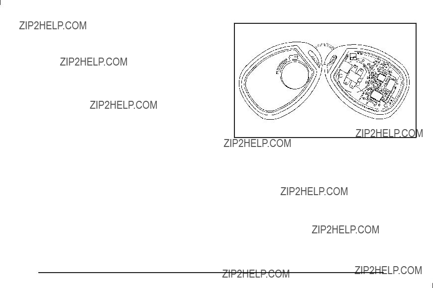
Programming Transmitters to the Vehicle
Only RKE transmitters programmed to this vehicle
will work. If a transmitter is lost or stolen, a replacement can be purchased and programmed through your dealer/retailer. When the replacement transmitter is programmed to this vehicle, all remaining transmitters must also be reprogrammed. Any lost or stolen transmitters will no longer work once the new transmitter is programmed. The vehicle can have a maximum of eight transmitters programmed to it. See ???Relearn Remote Key??? under DIC Operation and Displays
(With DIC Buttons) on page
Battery Replacement
Replace the battery if the REPLACE BATTERY IN REMOTE KEY message displays in the DIC. See ???REPLACE BATTERY IN REMOTE KEY??? under DIC Warnings and Messages on page
Notice: When replacing the battery, do not touch any of the circuitry on the transmitter. Static from your body could damage the transmitter.
To replace the battery:
1.Separate the transmitter with a ???at, thin object inserted into the notch on the side.
2.Remove the old battery. Do not use a metal object.
3.Insert the new battery, positive side facing down. Replace with a CR2032 or equivalent battery.
4.Snap the transmitter back together.

Remote Vehicle Start
Your vehicle may have a remote starting feature. This feature allows you to start the engine from outside of the vehicle. It may also start up the vehicle???s heating or air conditioning systems and rear window defogger. Normal operation of the system will return after the key is turned to the ON/RUN position.
If your vehicle has an automatic climate control system, the climate control system will default to a heating or cooling mode depending on the outside temperatures.
If your vehicle does not have an automatic climate control system, the system will turn on at the setting the vehicle was set to when the vehicle was last turned off.
During a remote start, if your vehicle has an automatic climate control system and heated seats, the heated seats will turn on during colder outside temperatures and will shut off when the key is turned to ON/RUN. If your vehicle does not have an automatic climate control system, during remote start, you will need to manually turn the heated seats on and off. See Heated Seats on page
Laws in some communities may restrict the use of remote starters. For example, some laws may require a person using the remote start to have the vehicle in view when doing so. Check local regulations for any requirements on remote starting of vehicles.
Do not use the remote start feature if your vehicle is low on fuel. Your vehicle may run out of fuel.
If your vehicle has the remote start feature, the RKE transmitter functions will have an increased range of operation. However, the range may be less while the vehicle is running.
There are other conditions which can affect the performance of the transmitter, see Remote Keyless Entry (RKE) System on page
/ (Remote Start): This button will be on the RKE transmitter if you have remote start.
To start the vehicle using the remote start feature:
1.Aim the transmitter at the vehicle.
2.Press and release the transmitter???s lock button. The vehicle???s doors will lock. Immediately press and hold the transmitter???s remote start button until the turn signal lights ???ash. If you cannot see
the vehicle???s lights, press and hold the remote start button for two to four seconds. Pressing the remote start button again after the vehicle has started will turn the engine off.
When the vehicle starts, the parking lamps will turn on and remain on while the vehicle is running.
If the vehicle is left running it will automatically shut off after 10 minutes unless a time extension has been done.

3.If it is the ???rst remote start since the vehicle has been driven, repeat these steps, while the engine is still running, to extend the engine running time by 10 minutes. Remote start can be extended one time.
After entering the vehicle during a remote start, insert and turn the key to RUN to drive the vehicle.
To manually shut off a remote start, do any of the following:
???Aim the RKE transmitter at the vehicle and press the remote start button until the parking lamps turn off.
???Turn on the hazard warning ???ashers.
???Turn the ignition switch on and then off.
The vehicle can be remote started two separate times between driving sequences. The engine will run for 10 minutes after each remote start.
Or, you can extend the engine run time by another 10 minutes within the ???rst 10 minute remote start time frame, and before the engine stops.
For example, if the lock button and then the remote start buttons are pressed again after the vehicle has been running for ???ve minutes, 10 minutes are added, allowing the engine to run for 15 minutes.
The additional ten minutes are considered a second remote vehicle start.
Once two remote starts, or a single remote start with one time extension has been done, the vehicle must be started with the key. After the key is removed from the ignition, the vehicle can be remote started again.
The vehicle cannot be remote started if the key is in the ignition, the hood is not closed, or if there is
an emission control system malfunction and the check engine light comes on.
Also, the engine will turn off during a remote vehicle start if the coolant temperature gets too high or if the oil pressure gets low.
Vehicles that have the remote vehicle start feature are shipped from the factory with the remote vehicle start system enabled. The system may be enabled or disabled through the DIC. See ???REMOTE START??? under DIC Vehicle Customization (With DIC Buttons) on page
Remote Start Ready
If your vehicle does not have the remote vehicle
start feature, it may have the remote start ready feature. This feature allows your dealer/retailer to add the manufacturer???s remote vehicle start feature.
See your dealer/retailer if you would like to add the manufacturer???s remote vehicle start feature to your vehicle.

Doors and Locks
Door Locks
{ CAUTION:
Unlocked doors can be dangerous.
???Passengers, especially children, can easily open the doors and fall out of a moving vehicle. When a door is locked, the handle will not open it. The chance of being thrown out of the vehicle in a crash is increased if the doors are not locked. So, all passengers should wear safety belts properly and the doors should be locked whenever the vehicle is driven.
???Young children who get into unlocked vehicles may be unable to get out. A child can be overcome by extreme heat and can suffer permanent injuries or even death from heat stroke. Always lock the vehicle whenever leaving it.
???Outsiders can easily enter through an unlocked door when you slow down or stop your vehicle. Locking your doors can help prevent this from happening.
There are several ways to lock and unlock your vehicle.
From the outside, use the Remote Keyless Entry (RKE) transmitter or the key in the driver???s door.
From the inside, use the power door locks or manual door locks. To lock or unlock the door with the manual locks, push down or pull up on the manual lock knob.
Power Door Locks
On vehicles with power door locks, the switches are located on the front doors.
" (Unlock): Press to unlock the doors.
Q (Lock): Remove the key from the ignition and press to lock the doors.
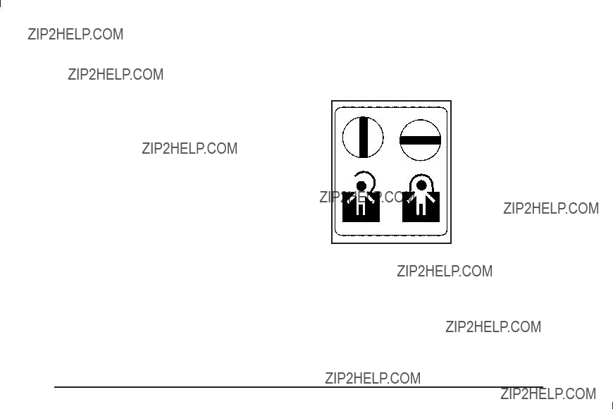
Delayed Locking
When locking the doors with the power lock switch and a door or the liftgate is open, the doors will lock ???ve seconds after the last door is closed. You will hear three chimes to signal that the delayed locking
feature is in use.
Pressing the power lock switch twice or the lock button on the RKE transmitter twice will override the delayed locking feature and immediately lock all the doors.
This feature will not operate if the key is in the ignition.
You can program this feature using the Driver Information Center (DIC). See DELAY DOOR LOCK under DIC Vehicle Customization (With DIC Buttons) on page
Programmable Automatic Door
Locks
Vehicles with an automatic lock/unlock feature enable you to program the vehicle???s power door locks. You can program this feature through the Driver Information Center (DIC). See DIC Vehicle Customization (With DIC Buttons) on page
Rear Door Security Locks
Your vehicle has rear door security locks. These prevent passengers from opening the rear doors from the inside.
The rear door security locks are located on the inside edge of each rear door.
The rear doors must be open to access them. The label showing lock and unlock positions is located near the lock.
To set the locks, do the following:
1.Insert the key into the security lock slot and turn it so the slot is in the horizontal position.
2.Close the door.

When you want to open a rear door when the security lock is on, do the following:
1.Unlock the door by lifting the rear door manual lock, using the power door lock switch, or the Remote Keyless Entry (RKE) transmitter, if the vehicle
has one.
2.Open the door from the outside.
To cancel the rear door security lock, do the following:
1.Unlock the door and open it from the outside.
2.Insert the key into the security lock slot and turn it so the slot is in the vertical position.
Lockout Protection
This feature protects you from locking the key in the vehicle when the key is in the ignition and a front door is open.
If the driver???s side power door lock switch is pressed when the driver???s door is open and the key is in
the ignition, all of the doors will lock and then the driver???s door will unlock.
If the passenger???s side power door lock switch is pressed when the front passenger???s door is open and the key is in the ignition, all of the doors will lock and then the front passenger???s door will unlock.
Liftgate/Liftglass
{ CAUTION:
It can be dangerous to drive with the liftglass or liftgate open because carbon monoxide (CO) gas can come into your vehicle. You cannot see or smell CO. It can cause unconsciousness and even death.
If you must drive with the liftglass or liftgate open, or if electrical wiring or other cable connections must pass through the seal between the body and the liftglass or liftgate:
???Make sure all other windows are shut.
???Turn the fan on your heating or cooling system to its highest speed with the recirculation mode off. That will force outside air into your vehicle. See Climate Control System on page
CAUTION: (Continued)
CAUTION: (Continued)
???If you have air outlets on or under the instrument panel, open them all the way.
???If your vehicle has a power liftgate, disable the power liftgate function.
See Engine Exhaust on page
If your vehicle has a power liftgate, see Power Liftgate on page
To unlock the liftgate, use the power door lock switch or press the door unlock button on the Remote Keyless Entry (RKE) transmitter twice. See Remote Keyless Entry (RKE) System Operation on page

On vehicles with a liftglass, press the button on the underside of the license pocket applique (A) to open it. The liftglass can also be opened by pressing the liftglass release button on the RKE.
To open the entire liftgate, press the touchpad on the underside of the liftgate handle (B). The vehicle must be in PARK (P) to open the liftgate. To close the liftgate, use the pull cup or pull strap as an aid.
The liftgate or liftglass cannot be opened if the rear wipers are in motion. Attempting to open the liftgate or liftglass while the rear wipers are in motion will cause the release of the liftglass or liftgate to delay until
the wipers are moved off the liftglass.
Both the liftglass and liftgate have an electric latch. If the battery is disconnected or has low voltage, the liftglass and liftgate will not open. The liftglass and liftgate will resume operation when the battery is reconnected and charged.
If the battery is properly connected and has adequate voltage, and the liftgate or liftglass still will not function, your vehicle should be taken to a dealership for service.
Power Liftgate
Power Liftgate Operation
{ CAUTION:
Exhaust gases can enter the vehicle if it is driven with the liftgate, trunk/hatch open, or with any objects that pass through the seal between the body and the trunk/hatch or liftgate. Engine exhaust contains Carbon Monoxide (CO) which cannot be seen or smelled. It can cause unconsciousness and even death.
If the vehicle must be driven with the liftgate, or trunk/hatch open:
???Close all of the windows.
???Fully open the air outlets on or under the instrument panel.
CAUTION: (Continued)
CAUTION: (Continued)
???Adjust the Climate Control system to a setting that brings in only outside air and set the fan speed to the highest setting. See Climate Control System in the Index.
???If the vehicle is equipped with a power liftgate, disable the power liftgate function.
For more information about carbon monoxide, see
Engine Exhaust on page
On vehicles with a power liftgate the button is located on the overhead console.
The vehicle must be in PARK (P) to use the power liftgate feature.
& : Press the top of the button to open or close the power liftgate.
OFF: Press the bottom of the button for manual operation of the power liftgate.

The taillamps will ???ash and a chime will sound when the power liftgate is moving.
{ CAUTION:
You or others could be injured if caught in the path of the power liftgate. Make sure there is no one in the way of the liftgate as it is opening and closing.
Notice: If you open the liftgate without checking for overhead obstructions such as a garage door,
you could damage the liftgate or the liftgate glass. Always check to make sure the area above and behind the liftgate is clear before opening it.
The power liftgate can be power opened and closed in the following ways:
???Press and hold the power liftgate button on the Remote Keyless Entry (RKE) transmitter until the liftgate starts moving. Remote Keyless Entry (RKE) System Operation on page
???Pressing the liftgate button on the overhead console.
???Pressing the touchpad switch on the outside liftgate handle.
Pressing the buttons, or touchpad switch a second time while the liftgate is moving reverses the direction.
l : The liftgate can also be closed by pressing the power liftgate button next to the liftgate latch.
Press the button a second time during liftgate operation to reverse that operation.
The power liftgate may be temporarily disabled under extreme temperatures, or under low battery conditions. If this occurs, the liftgate can still be operated manually.
If you shift the transmission out of PARK (P) while the power function is in progress, the liftgate power function will continue to completion. If you shift the transmission out of PARK (P) and accelerate before the power liftgate latches closed, the liftgate may reverse to the open position. Cargo could fall out of the vehicle. Always make sure the power liftgate is closed and latched before you drive away.
If you power open the liftgate and the liftgate support struts have lost pressure, the lights will ???ash and a chime will sound. The liftgate will stay open temporarily, then slowly close. See your dealer/retailer for service before using the liftgate.
Obstacle Detection Features
If the liftgate encounters an obstacle during a power open or close cycle, a warning chime will sound and the liftgate will automatically reverse direction to the full closed or open position. After removing the obstruction, the power liftgate operation can be used again. If the liftgate encounters multiple obstacles on the same power cycle, the power function will deactivate, and you must manually open or close the liftgate. The REAR ACCESS OPEN warning message in the Driver Information Center (DIC) will indicate that the liftgate is open. After removing the obstructions, manually open the liftgate to the full open position or close the liftgate to the fully closed and latched position. The liftgate will now resume normal power operation.
Your vehicle has pinch sensors located on the side edges of the liftgate. If an object is caught between the liftgate and the body and presses against this sensor, the liftgate will reverse direction and open fully.
The liftgate will remain open until it is activated again or closed manually. Do not force the liftgate open
or closed during a power cycle.

Manual Operation of Power Liftgate
To change the liftgate to manual operation, press the switch on the overhead console to the OFF position.
With the power liftgate disabled and all of the doors unlocked, the liftgate can be manually opened and closed.
To open the liftgate, press the touchpad on the handle on the outside of the liftgate, and lift the gate open.
To close the liftgate, use the pull cup to lower the liftgate and close. The liftgate latch will power close. Always close the liftgate before driving.
If the RKE button or the power close button on the liftgate is pressed while power operation is disabled, the lights will ???ash three times, but the liftgate will not move.
It is not recommended that you drive with the liftgate open, however, if you must drive with the liftgate open, the liftgate should be set to manual operation by pressing the OFF switch on the center console.
The liftgate has an electric latch. If the battery is disconnected or has low voltage, the liftgate will not open. The liftgate will resume operation when the battery is reconnected and charged.
If the battery is properly connected with adequate voltage, the switch is not disabled, and the liftgate still will not function, your vehicle should be taken to a dealer/ retailer for service.
Power Assist Steps
Your vehicle may have power assist steps.
The power assist steps automatically extend from beneath the vehicle on the side in which the door has been opened. Once the door is closed, the assist steps automatically move back under the vehicle after a
brief delay. The vehicle must not be moving for the assist steps to extend or retract.
The switch used to disable the power assist steps is located on the center console below the climate control system.
The assist steps cannot be disabled in the extended position.

Windows
{ CAUTION:
Leaving children, helpless adults, or pets in a vehicle with the windows closed is dangerous. They can be overcome by the extreme heat and suffer permanent injuries or even death from heat stroke. Never leave a child, a helpless adult, or a pet alone in a vehicle, especially with the windows closed in warm or hot weather.

Power Windows
{ CAUTION:
Leaving children in a vehicle with the keys is dangerous for many reasons, children or others could be badly injured or even killed. They could operate the power windows or other controls or even make the vehicle move. The windows will function and they could be seriously injured or killed if caught in the path of a closing window. Do not leave keys in a vehicle with children.
When there are children in the rear seat use the window lockout button to prevent unintentional operation of the windows.
The power window controls are located on each of the side doors.
Driver???s Side shown
The driver???s door also has switches that control the passenger and rear windows. The power windows work when the ignition has been turned to ACC/ACCESSORY, ON/RUN or when Retained Accessory Power (RAP) is active. See Retained Accessory Power (RAP) on
page
Press the switch to lower the window.
Pull up on the front edge of the switch to raise the window.

Windows with an
Window Lockout
o (Window Lockout): The window lockout switch is located with the power window switches on the driver???s door armrest. This feature prevents the rear passenger windows from operating, except from the driver???s position. Press the switch to turn the lockout feature on or off.
An indicator light will come on to show the lockout feature is on.
Sun Visors
Pull the sun visor down to block glare. Detach the sun visor from the center mount and slide it along the rod from
side of the front window. Swing the sun visor to the side to cover the side window. It can be moved along the rod from
Lighted Visor Vanity Mirror
Your vehicle may have lighted visor vanity mirrors on both the driver???s and passenger???s sun visors. Pull the sun visor down and lift the mirror cover to turn the lamps on.

Vehicle theft is big business, especially in some cities. This vehicle has
Content
Your vehicle may have a content
This is the security light.
To arm the
1.Open the door.
2.Lock the door with the Remote Keyless Entry (RKE) transmitter or the power door lock switch. The security light will come on to inform the driver the system is arming. If a door is open when the doors are locked, the security light will ???ash.
If the delayed locking feature is turned on, the
page
3.Close all doors. The security light should go off after about 30 seconds. The alarm is not armed until the security light goes off.
If a locked door is opened without using the RKE transmitter, a ten second

The
To avoid setting off the alarm by accident:
???If you do not want to activate the
???Always unlock the doors with the RKE transmitter. Unlocking a door any other way will set off the alarm if it is armed.
If you set off the alarm by accident, press unlock on the RKE transmitter or place the key in the ignition and turn it to START to turn off the alarm. The alarm will not stop if you try to unlock a door any other way.
Testing the Alarm
To test the alarm:
1.From inside the vehicle, lower the driver???s window and open the driver???s door.
2.Activate the system by locking the doors with the power door lock switch while the door is open, or with the RKE transmitter.
3.Get out of the vehicle, close the door and wait for the security light to go out.
4.Then reach in through the window, unlock the door with the manual door lock and open the door.
This should set off the alarm.
While the alarm is set, the power door unlock switch will not work.
If the alarm does not sound when it should but the headlamps ???ash, check to see if the horn works. The horn fuse may be blown. To replace the fuse, see Fuses and Circuit Breakers on page
If the alarm does not sound or the headlamps do not ???ash, the vehicle should be serviced by your dealer/retailer.

Immobilizer
The
This device complies with Part 15 of the FCC Rules. Operation is subject to the following two conditions:
1.This device may not cause harmful interference.
2.This device must accept any interference received, including interference that may cause undesired operation.
This device complies with
1.This device may not cause interference.
2.This device must accept any interference received, including interference that may cause undesired operation of the device.
Changes or modi???cations to this system by other than an authorized service facility could void authorization to use this equipment.
Immobilizer Operation
Your vehicle has
The system is automatically armed when the key is removed from the ignition.
The system is automatically disarmed when the key is turned to ON/RUN, ACC/ACCESSORY or START from the LOCK/OFF position.
You do not have to manually arm or disarm the system.
The security light will come on if there is a problem with arming or disarming the
When the
If the engine does not start and the security light on the instrument panel cluster comes on when trying to start the vehicle, there may be a problem with your
If the engine still does not start, and the key appears to be undamaged, try another ignition key. At this time, you may also want to check the fuse, see Fuses
and Circuit Breakers on page
It is possible for the
See your dealer/retailer or a locksmith who can service
To program the new additional key:
1.Verify that the new key has a 1 stamped on it.
2.Insert the original, already programmed, key in the ignition and start the engine. If the engine will not start, see your dealer/retailer for service.
3.After the engine has started, turn the key to LOCK/OFF, and remove the key.
4.Insert the new key to be programmed and turn it to the ON/RUN position within ???ve seconds of turning the ignition to the LOCK/OFF position in Step 3.
The security light will turn off once the key has been programmed.
5.Repeat Steps 1 through 4 if additional keys are to be programmed.
If you lose or damage your
Do not leave the key or device that disarms or deactivates the theft deterrent system in the vehicle.
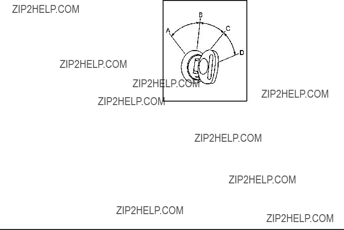
Starting and Operating Your
Vehicle
New Vehicle
Notice: The vehicle does not need an elaborate
???Keep your speed at 55 mph (88 km/h) or less for the ???rst 500 miles (805 km).
???Do not drive at any one constant speed, fast or slow, for the ???rst 500 miles (805 km). Do not make
???Avoid making hard stops for the ???rst 200 miles (322 km) or so. During this time the new brake linings are not yet broken in. Hard stops
with new linings can mean premature wear and earlier replacement. Follow this
???Do not tow a trailer during
Following
Ignition Positions
The ignition switch has four different positions.
To shift out of P (Park), the ignition must be in ON/RUN or ACC/ACCESSORY and the regular brake pedal must be applied.
A (LOCK/OFF): This position locks the ignition. It also locks the transmission on automatic transmission vehicles. The key can be removed in LOCK/OFF.
On vehicles with an automatic transmission, the shift lever must be in P (Park) to turn the ignition switch to LOCK/OFF.
The steering can bind with the wheels turned off center. If this happens, move the steering wheel from right
to left while turning the key to ACC/ACCESSORY. If this doesn???t work, then the vehicle needs service.
Notice: Using a tool to force the key to turn in the ignition could cause damage to the switch or break the key. Use the correct key, make sure it is all the way in, and turn it only with your hand.
If the key cannot be turned by hand, see your dealer/retailer.
B (ACC/ACCESSORY): This position lets things like the radio and the windshield wipers operate while the engine is off. Use this position if the vehicle must be pushed or towed.
C (ON/RUN): This position can be used to operate the electrical accessories and to display some instrument panel cluster warning and indicator lights. The switch stays in this position when the engine is running.
The transmission is also unlocked in this position on automatic transmission vehicles.
If you leave the key in the ACC/ACCESSORY or ON/ RUN position with the engine off, the battery could be drained. You may not be able to start the vehicle if the battery is allowed to drain for an extended period of time.
D (START): This is the position that starts the engine. When the engine starts, release the key. The ignition switch returns to ON/RUN for driving.
A warning tone will sound when the driver door is opened, the ignition is in ACC/ACCESSORY or LOCK/OFF and the key is in the ignition.

Retained Accessory Power (RAP)
The following vehicle accessories can be used for up to 10 minutes after the engine is turned off:
???Audio System
???Power Windows
???OnStar?? System (if equipped)
???Sunroof (if equipped)
These features work when the key is in ON/RUN or ACC/ACCESSORY. Once the key is turned from ON/RUN to LOCK/OFF, the windows and sunroof continue to work up to 10 minutes until any door
is opened. The radio continues to work for up to 10 minutes or until the driver door is opened.
Starting the Engine
If the vehicle is a
Move the shift lever to P (Park) or N (Neutral). The engine will not start in any other position. To restart the engine when the vehicle is are already moving, use
N (Neutral) only.
Notice: Do not try to shift to P (Park) if the vehicle is moving. If you do, you could damage the transmission. Shift to P (Park) only when the vehicle is stopped.

Starting Procedure
1.With your foot off the accelerator pedal, turn the ignition key to START. When the engine starts, let go of the key. The idle speed will go down as the engine gets warm. Do not race the engine immediately after starting it. Operate the engine and transmission gently to allow the oil to warm up and lubricate all moving parts.
The vehicle has a
Notice: Cranking the engine for long periods of time, by returning the key to the START position immediately after cranking has ended, can overheat and damage the cranking motor, and drain the battery. Wait at least 15 seconds between each try, to let the cranking motor cool down.
2.If the engine does not start after
Try pushing the accelerator pedal all the way to the ???oor and holding it there as you hold the key in START for up to a maximum of 15 seconds. Wait at least 15 seconds between each try, to allow the
cranking motor to cool down. When the engine starts, let go of the key and accelerator. If the vehicle starts brie???y but then stops again, do the same thing.
This clears the extra gasoline from the engine.
Do not race the engine immediately after starting it. Operate the engine and transmission gently until the oil warms up and lubricates all moving parts.
Notice: The engine is designed to work with the electronics in the vehicle. If you add electrical parts or accessories, you could change the way the engine operates. Before adding electrical equipment, check with your dealer/retailer. If you do not, the engine might not perform properly. Any resulting damage would not be covered by the vehicle warranty.
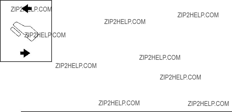
Adjustable Throttle and Brake Pedal
On vehicles with this feature, you can change the position of the throttle and brake pedals.
No adjustment to the pedals can be made when the vehicle is in R (Reverse) or while using the cruise control.
The switch used to adjust the pedals is located on the instrument panel below the climate control system.
Press the arrow at the bottom of the switch to move the pedals closer to your body. Press the arrow at the top of the switch to move the pedals away from your body.
Before you start driving, fully press the brake pedal to con???rm the adjustment is right for you. While driving, make only small adjustments.
The vehicle may have a memory function which lets pedal settings be saved and recalled. See Memory Seat, Mirrors, and Pedals on page
Engine Coolant Heater
The engine coolant heater can provide easier starting and better fuel economy during engine
the
To Use the Engine Coolant Heater
1.Turn off the engine.
2.Open the hood and unwrap the electrical cord. The cord is located on the driver???s side of the engine compartment, near the power steering ???uid reservoir.
3.Plug the cord into a normal, grounded
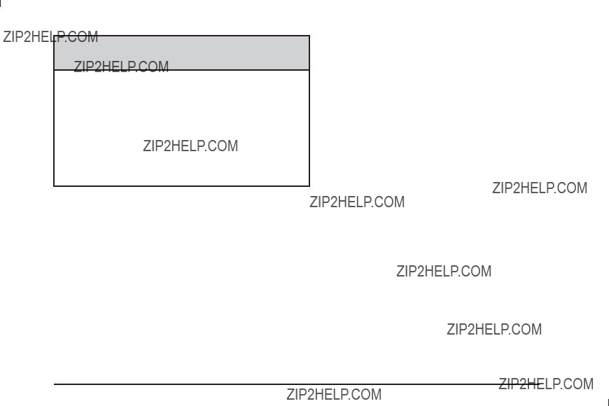
{ CAUTION:
Plugging the cord into an ungrounded outlet could cause an electrical shock. Also, the wrong kind of extension cord could overheat and cause a ???re.
You could be seriously injured. Plug the cord into a properly grounded
15amps.
4.Before starting the engine, be sure to unplug and store the cord as it was before to keep it away from moving engine parts. If you do not, it could be damaged.
The length of time the heater should remain plugged in depends on several factors. Ask a dealer/retailer in the area where you will be parking the vehicle for the best advice on this.
Active Fuel Management???
Vehicles with V8 engines may have Active Fuel Management???. This system allows the engine to operate on either all or half of its cylinders, depending on the driving conditions.
When less power is required, such as cruising at a constant vehicle speed, the system will operate in the half cylinder mode, allowing the vehicle to achieve better fuel economy. When greater power demands are required, such as accelerating from a stop, passing,
or merging onto a freeway, the system will maintain
If your vehicle has an Active Fuel Management??? indicator, see DIC Operation and Displays (With DIC Buttons) on page

Automatic Transmission Operation
If the vehicle is a
If the vehicle is has an automatic transmission, it has an electronic shift position indicator within the instrument panel cluster. This display comes on when the ignition key is turned to the ON/RUN position.
There are several different positions for the shift lever.
Automatic Transmission
Hevay Duty
Shown (Light Duty Similar)
See ???Range Selection Mode??? later in this section.
P (Park): This position locks the rear wheels. It is the best position to use when starting the engine because the vehicle cannot move easily. When parked on a hill, especially when the vehicle has a heavy load, you might notice an increase in the effort to shift out of
P (Park). See Torque Lock (Automatic Transmission) under Shifting Into Park on page

{ CAUTION:
It is dangerous to get out of the vehicle if the shift lever is not fully in P (Park) with the parking brake ???rmly set. The vehicle can roll.
Do not leave the vehicle when the engine is running unless you have to. If you have left the engine running, the vehicle can move suddenly. You or others could be injured. To be sure the vehicle will not move, even when you are on fairly level ground, always set the parking brake and move the shift lever to P (Park). See Shifting Into Park on page
Towing a Trailer on page
{ CAUTION:
If you have
P (Park) ??? if the transfer case is in Neutral. So, be sure the transfer case is in a drive gear,
R (Reverse): Use this gear to back up.
Notice: Shifting to R (Reverse) while the vehicle is moving forward could damage the transmission. The repairs would not be covered by the vehicle warranty. Shift to R (Reverse) only after the vehicle is stopped.
To rock the vehicle back and forth to get out of snow, ice, or sand without damaging the transmission,
see If Your Vehicle is Stuck in Sand, Mud, Ice, or Snow on page

N (Neutral): In this position, the engine does not connect with the wheels. To restart the engine when the vehicle is already moving, use N (Neutral) only. Also, use N (Neutral) when the vehicle is being towed.
{ CAUTION:
Shifting into a drive gear while the engine is running at high speed is dangerous. Unless your foot is ???rmly on the brake pedal, the vehicle could move very rapidly. You could lose control and hit people or objects. Do not shift into a drive gear while the engine is running at high speed.
Notice: Shifting out of P (Park) or N (Neutral) with the engine running at high speed may damage
the transmission. The repairs would not be covered by the vehicle warranty. Be sure the engine is
not running at high speed when shifting the vehicle.
D (Drive): This position is for normal driving. It provides the best fuel economy. If you need more power for passing, and you are:
???Going less than about 35 mph (55 km/h), push the accelerator pedal about halfway down.
???Going about 35 mph (55 km/h) or more, push the accelerator all the way down.
By doing this, the vehicle shifts down to the next gear and has more power.
D (Drive) can be used when towing a trailer, carrying a heavy load, driving on steep hills, or for
Downshifting the transmission in slippery road conditions could result in skidding. See Skidding under
Loss of Control on page
The vehicle has a shift stabilization feature that adjusts the transmission shifting to the current driving conditions in order to reduce rapid upshifts and downshifts. This shift stabilization feature is designed to determine, before making an upshift, if the engine is able to maintain vehicle speed by analyzing things such as vehicle speed, throttle position, and vehicle load. If the shift stabilization feature determines that a current vehicle speed cannot be maintained, the transmission does not upshift and instead holds the current gear. In some cases, this could appear to be a delayed shift, however the transmission is operating normally.
The vehicle???s transmission uses adaptive shift controls. Adaptive shift controls continually compares key shift parameters to
When temperatures are very cold, the
M (Manual Mode): This position is available on vehicles with the
this feature, see Range Select Mode
3 (Third): This position is also used for normal driving. It reduces vehicle speed more than D (Drive) without using the brakes. You might choose 3 (Third) instead of D (Drive) when driving on hilly, winding roads, when towing a trailer, so there is less shifting between gears and when going down a steep hill.
2 (Second): This position reduces vehicle speed even more than 3 (Third) without using the brakes. You can use 2 (Second) on hills. It can help control vehicle speed as you go down steep mountain roads, but then you would also want to use the brakes off and on.
If you manually select 2 (Second) in an automatic transmission, the transmission will start in second gear. You can use this feature for reducing the speed of
the rear wheels when you are trying to start the vehicle from a stop on slippery road surfaces.

1 (First): For the
For a
You can use it for major/severe downgrades and
Notice: Spinning the tires or holding the vehicle in one place on a hill using only the accelerator pedal may damage the transmission. The repair will not be covered by the vehicle warranty. If you are stuck, do not spin the tires. When stopping on a hill, use the brakes to hold the vehicle in place.
Range Selection Mode
Base trim shown (uplevel similar)
The vehicle may have a Range Selection Mode.
The Range Selection Mode helps control the vehicle???s transmission and vehicle speed while driving down hill or towing a trailer by letting you select a desired range of gears.

To use this feature, do the following:
1.Move the shift lever to M (Manual Mode).
2.Press the plus/minus buttons, located on the steering column shift lever, to select the desired range of gears for the current driving conditions.
When M (Manual Mode) is selected a number displays next to the M, indicating the current gear.
This number is the highest gear that can be used. However, the vehicle can automatically shift to lower gears as it adjusts to driving conditions. This means that all gears below that number are available. When 5 (Fifth) is selected, 1 (First) through 5 (Fifth) gears are automatically shifted by the vehicle, but 6 (Sixth) cannot be used until the plus/minus button located on the steering column lever is used to change to the gear.
Grade Braking is not available when Range Selection Mode is active. See Tow/Haul Mode on page
While using Range Selection Mode, cruise control and the Tow/Haul mode can be used.
Notice: Spinning the tires or holding the vehicle in one place on a hill using only the accelerator pedal may damage the transmission. The repair will not be covered by the vehicle warranty. If you are stuck, do not spin the tires. When stopping on a hill, use the brakes to hold the vehicle in place.
Low Traction Mode
If the vehicle has the
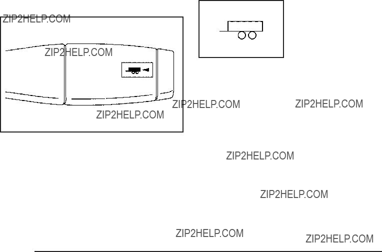
Tow/Haul Mode
The vehicle has a Tow/Haul mode. The selector button is located on the end of the column shift lever. You can use this feature to assist when towing or hauling a heavy load or if there is a need to charge a battery installed in a trailer. See Towing a Trailer
on page

Grade Braking
Automatic Transmission)
The Grade Braking shift modes can be activated by pressing the button on the end of the shift control lever. While in Range Selection Mode, Grade Braking is deactivated allowing the driver to select a desired range of gears.
Grade Braking is only active while the Tow/Haul Mode is selected and you are not in the Range Selection Mode. See ???Tow/Haul Mode listed previously and Automatic Transmission Operation on page
it detects when the truck is on a downhill grade and the driver desires to slow the vehicle by pressing the brake.
Also see Towing a Trailer on page
Cruise Grade Braking
Cruise Grade Braking assists when driving on a downhill grade. It maintains vehicle speed by automatically implementing a shift schedule that uses the engine
and the transmission to slow the vehicle. Cruise Grade Braking operates while Cruise Control is engaged in Tow/Haul mode to assist in maintaining vehicle speed under loaded vehicle conditions. It utilizes vehicle acceleration and deviation from desired speed to determine the correct gear for the operating condition. If vehicle speed is above the desired speed the transmission will downshift to slow the vehicle.
If vehicle speed is near or below desired speed the trans will upshift, allowing vehicle speed to increase.
While in the Range Select Mode (RSM) mode, Cruise Grade Braking is not available.
See Automatic Transmission Operation on page

If the vehicle has
Notice: Driving on clean, dry pavement in
While driving on clean dry pavement and during tight turns, you may experience a vibration in the steering system.
The vehicle has StabiliTrak??. Shifting into
Front Axle
The front axle engages and disengages automatically when you shift the transfer case. Some delay for
the axle to engage or disengage is normal.
Automatic Transfer Case
The transfer case knob is located to the left of the instrument panel cluster.
Use this dial to shift into and out of
You can choose among ???ve driving settings:
Indicator lights in the switches show you which setting you are in. The indicator lights will come on brie???y when you turn on the ignition and the last chosen setting will stay on. If the lights do not come on, you should take the vehicle to your dealer/retailer for service. An indicator light will ???ash while shifting. It will stay on when the shift is completed. If for some reason the transfer case cannot make a requested shift, it will return to the last chosen setting.
2 m
AUTO (Automatic
this mode results in slightly lower fuel economy than
4 m
4 n
The vehicle has StabiliTrak??. Shifting into
{ CAUTION:
Shifting the transfer case to N (Neutral) can cause the vehicle to roll even if the transmission is in
P (Park). You or someone else could be seriously injured. Be sure to set the parking brake before placing the transfer case in N (Neutral). See
Parking Brake on page
N (Neutral): Shift the vehicle???s transfer case to N (Neutral) only when towing the vehicle. See Recreational Vehicle Towing on page
If the SERVICE 4 WHEEL DRIVE message stays on, you should take the vehicle to your dealer/retailer
for service. See ???SERVICE 4 WHEEL DRIVE message??? under DIC Warnings and Messages on page

Shifting Into
Turn the knob to the
Shifting Into
Turn the knob to the
This can be done at any speed, except when shifting from
See shifting out of
Shifting Into
When
To shift to the
the transmission in N (Neutral). The preferred method for shifting into
the vehicle moving 1 to 2 mph (1.6 to 3.2 km/h). Turn the knob to the
You must wait for the
Notice: Shifting the transmission into gear before the
The vehicle may have signi???cant engagement noise and bump when shifting between
If the knob is turned to the
30 seconds and not complete the shift unless the vehicle is moving less than 3 mph (5 km/h) and the transmission is in N (Neutral). After 30 seconds the transfer case
will shift to

Shifting Out of
To shift from
in ON/RUN. The preferred method for shifting out of
Notice: Shifting the transmission into gear before the
The vehicle may have signi???cant engagement noise and bump when shifting between
If the knob is turned to the
Shifting into Neutral
To shift the transfer case to N (Neutral) do the following:
1.Make sure the vehicle is parked so that it will not roll.
2.Set the parking brake and apply the regular brake pedal. See Parking Brake on page
3.Start the vehicle or turn the ignition to ON/RUN.
4.Put the transmission in N (Neutral).
5.Shift the transfer case to
6.Turn the transfer case dial clockwise to N (Neutral) until it stops and hold it there until the N (Neutral) light starts blinking. This will take at least
10 seconds. Then slowly release the dial to the

7.If the engine is running, verify that the transfer case is in N (Neutral) by shifting the transmission to
R (Reverse) for one second, then shift the transmission to D (Drive) for one second.
8.Turn the ignition to ACC/ACCESSORY, which will turn the engine off.
9.Place the transmission shift lever in P (Park).
10.Release the parking brake prior to moving the vehicle.
11.Turn the ignition to LOCK/OFF.
Shifting Out of Neutral
To shift out of N Neutral do the following:
1.Set the parking brake and apply the regular brake pedal.
2.Turn the ignition to ON/RUN with the engine off, and shift the transmission to N (Neutral).
3.Turn the transfer case dial to the desired transfer case shift position
After the transfer case has shifted out of N (Neutral), the N (Neutral) light will go out.
4.Release the parking brake prior to moving the vehicle.
Notice: Shifting the transmission into gear before the
5.Start the engine and shift the transmission to the desired position.
Excessively shifting the transfer case into or out of the different modes may cause the transfer case to enter the shift protection mode. This will protect the transfer case from possible damage and will only allow the transfer case to respond to one shift per 10 seconds. The transfer case may stay in this mode for up to three minutes.
Parking Brake
For vehicles with a release handle, set the parking brake by holding the regular brake pedal down, then pushing down the parking brake pedal.
If the ignition is on, the brake system warning light will come on. See Brake System Warning Light on page
A chime sounds and the warning light ???ashes when the parking brake is applied and the vehicle is moving at least 5 mph (8 km/h).
To release the parking brake, hold the regular brake pedal down. Then pull the bottom edge of the lever with the parking brake symbol, located above the parking brake pedal.
If the ignition is on when the parking brake is released, the brake system warning light goes off.
Notice: Driving with the parking brake on can overheat the brake system and cause premature wear or damage to brake system parts. Make sure that the parking brake is fully released and the brake warning light is off before driving.
If you are towing a trailer and are parking on any hill, see Towing a Trailer on page

For vehicles without a release handle, set the parking brake by holding the regular brake pedal down,
then pushing down the parking brake pedal.
If the ignition is on, the brake system warning light will come on. See Brake System Warning Light on
page
Notice: Driving with the parking brake on can overheat the brake system and cause premature wear or damage to brake system parts. Make sure that the parking brake is fully released and the brake warning light is off before driving.
To release the parking brake, hold the regular brake pedal down, then push down momentarily on the parking brake pedal until you feel the pedal release. Slowly
pull your foot up off the park brake pedal. If the parking brake is not released when you begin to drive, the brake system warning light will ???ash and a chime will sound warning you that the parking brake is still on.
If you are towing a trailer and are parking on a hill, see
Towing a Trailer on page
Shifting Into Park
{ CAUTION:
It can be dangerous to get out of the vehicle if the shift lever is not fully in P (Park) with the parking brake ???rmly set. The vehicle can roll. If you have left the engine running, the vehicle can move suddenly. You or others could be injured. To be sure the vehicle will not move, even when you are on
fairly level ground, use the steps that follow. With
N (Neutral), the vehicle will be free to roll, even if the shift lever is in P (Park). So, be sure the transfer case is in a drive gear ??? not in N (Neutral). If you are pulling a trailer, see Towing a Trailer on
page
1.Hold the brake pedal down, then set the parking brake.
See Parking Brake on page
2.Move the shift lever into the P (Park) position by pulling the shift lever toward you and moving it up as far as it will go.
3.Be sure the transfer case is in a drive gear ??? not in N (Neutral).
4.Turn the ignition key to LOCK/OFF.
5.Remove the key and take it with you. If you can leave the vehicle with the ignition key in your hand, the vehicle is in P (Park).
Leaving the Vehicle With the Engine
Running
{ CAUTION:
It can be dangerous to leave the vehicle with the engine running. The vehicle could move suddenly if the shift lever is not fully in P (Park) with the parking brake ???rmly set.
If you have
And, if you leave the vehicle with the engine running, it could overheat and even catch ???re. You or others could be injured. Do not leave the vehicle with the engine running unless you have to.
If you have to leave the vehicle with the engine running, be sure your vehicle is in P (Park) and the parking brake is ???rmly set before you leave it. After you move the shift lever into P (Park), hold the regular brake pedal down.
Then, see if you can move the shift lever away from
P (Park) without ???rst pulling it toward you. If you can, it means that the shift lever was not fully locked into
P (Park).
Torque Lock
If you are parking on a hill and you do not shift your transmission into P (Park) properly, the weight of
the vehicle may put too much force on the parking pawl in the transmission. You may ???nd it difficult to pull the shift lever out of P (Park). This is called torque lock.
To prevent torque lock, set the parking brake and then shift into P (Park) properly before you leave the driver seat. To ???nd out how, see Shifting Into Park on page
When you are ready to drive, move the shift lever out of P (Park) before you release the parking brake.
If torque lock does occur, you may need to have another vehicle push yours a little uphill to take some of the pressure from the parking pawl in the transmission, then you will be able to pull the shift lever out of P (Park).

Shifting Out of Park
This vehicle is equipped with an electronic shift lock release system. The shift lock release is designed to:
???Prevent ignition key removal unless the shift lever is in P (Park) with the shift lever button fully released, and
???Prevent movement of the shift lever out of P (Park), unless the ignition is in ON/RUN or
ACC/ACCESSORY and the regular brake pedal is applied.
The shift lock release is always functional except in the case of an uncharged or low voltage (less than 9 volt) battery.
If the vehicle has an uncharged battery or a battery with low voltage, try charging or jump starting the battery. See Jump Starting on page
To shift out of P (Park) use the following:
1.Apply the brake pedal.
2.Move the shift lever to the desired position.
If you still are unable to shift out of P (Park):
1.Ease the pressure on the shift lever.
2.While holding down the brake pedal, press the shift lever all the way into P (Park).
3.Move the shift lever to the desired position.
If you are still having a problem shifting, then have the vehicle serviced soon.
Parking Over Things That Burn
{ CAUTION:
Things that can burn could touch hot exhaust parts under the vehicle and ignite. Do not park over papers, leaves, dry grass, or other things that can burn.
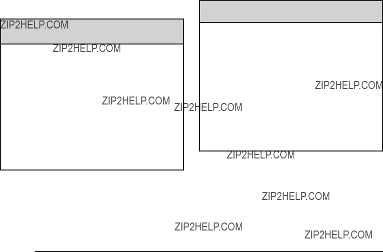
Engine Exhaust
{ CAUTION:
Engine exhaust contains Carbon Monoxide (CO) which cannot be seen or smelled. Exposure to CO can cause unconsciousness and even death.
Exhaust may enter the vehicle if:
???The vehicle idles in areas with poor ventilation (parking garages, tunnels, deep snow that may block underbody air???ow or tail pipes).
???The exhaust smells or sounds strange or different.
???The exhaust system leaks due to corrosion or damage.
CAUTION: (Continued)
CAUTION: (Continued)
???The vehicle???s exhaust system has been modi???ed, damaged or improperly repaired.
???There are holes or openings in the vehicle body from damage or
If unusual fumes are detected or if it is suspected that exhaust is coming into the vehicle:
???Drive it only with the windows completely down.
???Have the vehicle repaired immediately.
Never park the vehicle with the engine running in an enclosed area such as a garage or a building that has no fresh air ventilation.
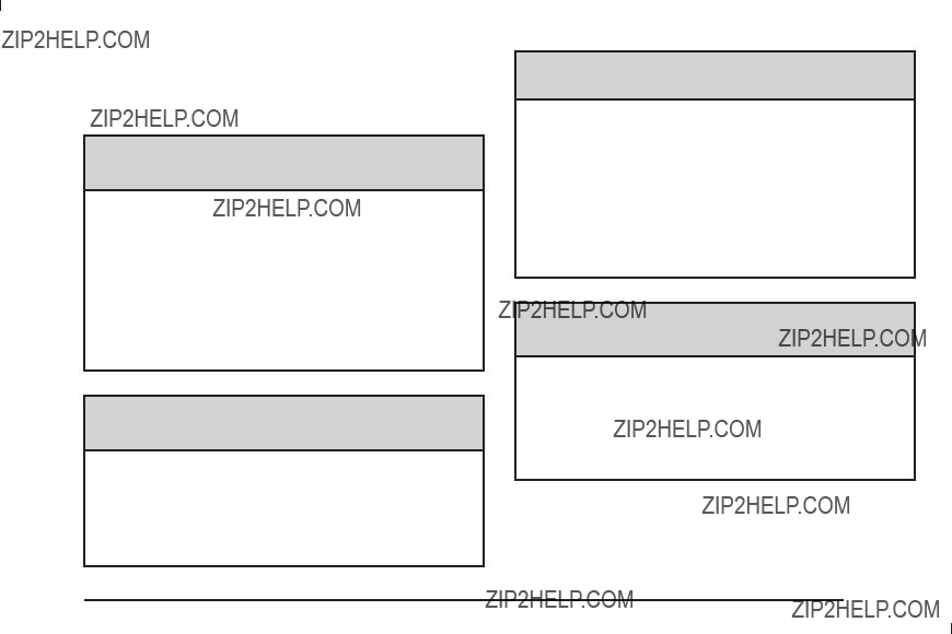
Running the Vehicle While Parked
It is better not to park with the engine running. But if you ever have to, here are some things to know.
{ CAUTION:
Idling a vehicle in an enclosed area with poor ventilation is dangerous. Engine exhaust may enter the vehicle. Engine exhaust contains Carbon Monoxide (CO) which cannot be seen or smelled. It can cause unconsciousness and even death. Never run the engine in an enclosed area that has no fresh air ventilation. For more information, see
Engine Exhaust on page
{ CAUTION:
It can be dangerous to get out of the vehicle if the automatic transmission shift lever is not fully in
P (Park) with the parking brake ???rmly set.
CAUTION: (Continued)
CAUTION: (Continued)
The vehicle can roll. Do not leave the vehicle when the engine is running unless you have to. If you have left the engine running, the vehicle can move suddenly. You or others could be injured. To be sure the vehicle will not move, even when you are on fairly level ground, always set the parking brake and move the shift lever to
P (Park).
{ CAUTION:
Follow the proper steps to be sure the vehicle will not move. See Shifting Into Park on page
If pulling a trailer, see Towing a Trailer on page

Mirrors
Manual Rearview Mirror
Hold the inside rearview mirror in the center to move it for a clearer view behind your vehicle. Adjust the mirror to avoid glare from the headlamps behind you. Push the tab forward for daytime use and pull it for nighttime use.
Automatic Dimming Rearview Mirror
The vehicle may have an automatic dimming inside rearview mirror.
Vehicles with OnStar?? have three additional control buttons for the OnStar?? system. See your dealer/retailer for more information about OnStar?? and how to subscribe to it. See OnStar?? System on page
O (On/Off): Press to turn the dimming feature on or off.
The vehicle may also have a Rear Vision Camera (RVC). See Rear Vision Camera (RVC) on page
If the vehicle has RVC, the O (On/Off) button for turning the automatic dimming feature on or off will not be available.
Automatic Dimming Mirror Operation
Automatic dimming reduces the glare from the headlamps of the vehicle behind you. The dimming feature comes on and the indicator light illuminates each time the ignition is turned to start.
Cleaning the Mirror
Do not spray glass cleaner directly on the mirror. Use a soft towel dampened with water.
Outside Manual Mirrors
Adjust the outside mirror so that the side of the vehicle and the area behind are seen.
Manually fold the mirrors inward to prevent damage when going through an automatic car wash. To fold, push the mirror toward the vehicle. Push the mirror outward, to return to its original position.
Using
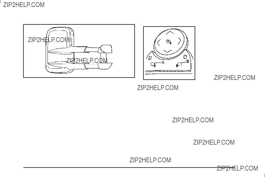
If the vehicle has towing mirrors, they can be adjusted for a clearer view of the objects behind you. Manually pull out the mirror head to extend it for better visibility when towing a trailer.
Manually fold the mirrors forward or rearward. The lower portion of the mirror is convex. A convex mirror???s surface is curved to see more from the driver seat.
The convex mirror can be adjusted manually to the driver preferred position for better vision.
The mirror may have a turn signal arrow that ???ashes in the direction of the turn or lane change.
Vehicles with outside power mirrors have the controls on the driver door armrest.
To adjust each mirror:
1.Press (A) or (B) to select the driver or passenger side mirror.
2.Press one of the four arrows located on the control pad to move the mirror to the desired direction.
3.Adjust each outside mirror so that a little of the vehicle and the area behind it can be seen.
4.Press either (A) or (B) again to deselect the mirror.
The mirrors may also include a memory function that works with the memory seats. See Memory Seat, Mirrors, and Pedals on page

Manually fold the mirrors inward to prevent damage when going through an automatic car wash. To fold, push the mirror toward the vehicle. Push the mirror outward, to return to its original position.
Outside Power Foldaway Mirrors
Vehicles with outside power foldaway mirrors have the controls located on the driver door armrest.
Mirror Adjustment
1.Press (C) to fold the mirrors out to the driving position.
2.Press (D) to fold the mirrors in to the folded position.
Resetting the Power Foldaway Mirrors
Reset the power foldaway mirrors if:
???The mirrors are accidentally obstructed while folding.
???They are accidentally manually folded/unfolded.
???The mirrors will not stay in the unfolded position.
???The mirrors shake and ???utter at normal driving speeds.
Fold and unfold them one time using the mirror controls to reset them to their normal position.
Turn Signal Indicator
The vehicle may have a turn signal indicator on the mirror. An arrow on the mirror ???ashes in the direction of the turn or lane change.
Ground Illumination Lamps
The mirrors may also include ground illumination lamps in the base of the mirror. These lamps help to see the area near the base of the front doors when it is dark out.
Outside Automatic Dimming Mirror
Vehicles with this feature have a driver outside mirror that adjusts for the glare of headlamps behind you. See Automatic Dimming Rearview Mirror on page
Park Tilt Mirrors
Vehicles with the memory package have a passenger and/or driver mirror that tilts to a preselected position when the vehicle is in R (Reverse). This feature lets the driver view the curb when parallel parking. The mirror(s) return to the original position when the vehicle is shifted out of R (Reverse), or the ignition is turned off.
Turn this feature on or off through the Driver Information Center (DIC). See DIC Vehicle Customization (With DIC Buttons) on page
Outside Convex Mirror
{ CAUTION:
A convex mirror can make things, like other vehicles, look farther away than they really are.
If you cut too sharply into the right lane, you could hit a vehicle on the right. Check the inside mirror or glance over your shoulder before changing lanes.
The passenger side mirror is convex shaped. A convex mirror???s surface is curved so more can be seen from the driver seat.
Outside Heated Mirrors
For vehicles with heated mirrors:
< (Rear Window Defogger): Press to heat the
mirrors.
See ???Rear Window Defogger??? under Dual Automatic Climate Control System on page
Side Blind Zone Alert (SBZA)
If your vehicle has the Side Blind Zone Alert (SBZA) system, see Side Blind Zone Alert (SBZA) on page
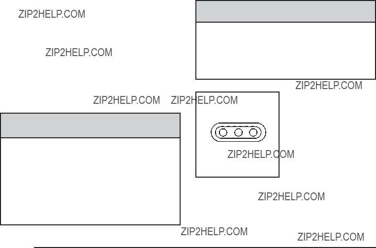
Object Detection Systems
Ultrasonic Rear Parking
Assist (URPA)
For vehicles with the Ultrasonic Rear Parking Assist (URPA) system, it operates at speeds less than 5 mph (8 km/h), and assists the driver with parking and avoiding objects while in R (Reverse). The sensors on the rear bumper are used to detect the distance to an object up to 8 feet (2.5 m) behind the vehicle, and at least 10 inches (25.4 cm) off the ground.
{ CAUTION:
The Ultrasonic Rear Parking Assist (URPA) system does not replace driver vision. It cannot detect:
???objects that are below the bumper, underneath the vehicle, or if they are too close or far from the vehicle
???children, pedestrians, bicyclists, or pets.
CAUTION: (Continued)
CAUTION: (Continued)
If you do not use proper care before and while backing; vehicle damage, injury, or death could occur. Even with URPA, always check behind the vehicle before backing up. While backing, be sure to look for objects and check the vehicle???s mirrors.
The display is located near the passenger side rear window and can be seen by looking over your right shoulder.
URPA uses three
How the System Works
URPA comes on automatically when the shift lever is moved into R (Reverse). The rear display brie???y illuminates to indicate the system is working.
URPA operates only at speeds less than 5 mph (8 km/h). If the vehicle is above this speed, the red light on the rear display will ???ash.
To be detected, objects must be at least 10 inches (25.4 cm) off the ground and below liftgate level. Objects must also be within 8 feet (2.5 m) from the rear bumper. This distance may be less during warmer or humid weather.
A single beep will sound the ???rst time an object is detected between 40 inches (1 m) and 8 feet (2.5 m) away. Beeping will occur continuously when the vehicle is at 23 inches (0.6 m) or closer to an object.
The following describes what will occur with the URPA display as the vehicle gets closer to a detected object:
The indicator light will come on and PARK ASSIST OFF displays on the Driver Information Center (DIC) to indicate that URPA is off, see DIC Warnings and Messages on page

When the System Does Not Seem to Work Properly
If the URPA system will not activate due to a temporary condition, the message PARK ASSIST OFF will be displayed on the DIC and a red light will be shown on the rear URPA display when the shift lever is moved into R (Reverse). This occurs under the following conditions:
???The driver disables the system.
???The ultrasonic sensors are not clean. Keep the vehicle???s rear bumper free of mud, dirt, snow, ice and slush. For cleaning instructions, see
Washing Your Vehicle on page
???A trailer was attached to the vehicle, or a bicycle or an object was hanging out of the liftgate during the last drive cycle, the red light may illuminate in
the rear display. Once the attached object is removed, URPA will return to normal operation.
???A tow bar is attached to the vehicle.
???The vehicle???s bumper is damaged. Take the vehicle to your dealer/retailer to repair the system.
???Other conditions may affect system performance, such as vibrations from a jackhammer or the compression of air brakes on a very large truck.
If the system is still disabled, after driving forward at least 15 mph (25 km/h), take the vehicle to your dealer/retailer.
Side Blind Zone Alert (SBZA)
The vehicle may have a Side Blind Zone Alert (SBZA) system. Read this entire section before using the system.
The SBZA system operates on a radio frequency subject to Federal Communications Commission (FCC) Rules and with Industry Canada.
This device complies with Part 15 of the FCC Rules. Operation is subject to the following two conditions:
1.This device may not cause harmful interference.
2.This device must accept any interference received, including interference that may cause undesired operation.
This device complies with
1.This device may not cause harmful interference.
2.This device must accept any interference received, including interference that may cause undesired operation.
Frequency of operation: 24.05GHz ??? 24.25GHz
Field Strength: Not greater than 2.5V/m peak (0.25V/m average) at a distance of 3m
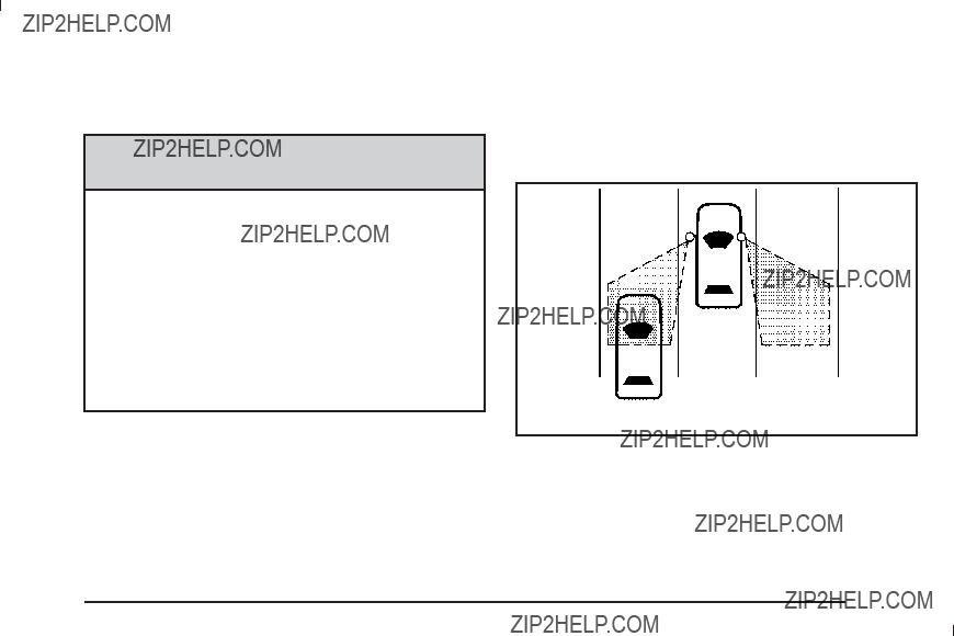
The manufacturer is not responsible for any radio or TV interference caused by unauthorized modi???cations to this equipment. Such modi???cations could void the user???s authority to operate the equipment.
{ CAUTION:
SBZA is only a lane changing aid and does not replace driver vision. SBZA does not detect:
???Vehicles outside the side blind zones which may be rapidly approaching.
???Pedestrians, bicyclists, or animals.
Failure to use proper care when changing lanes may result in damage to the vehicle, injury, or death. Always check the outside and rearview mirrors, glance over your shoulder, and use the turn signal before changing lanes.
When the system detects a vehicle in the side blind zone, amber SBZA displays light up in the side mirrors. This indicates that it may be unsafe to change lanes. Before making a lane change, always check the SBZA display, check the outside and rearview mirrors, look over your shoulder for vehicles and hazards, and
use the turn signal.
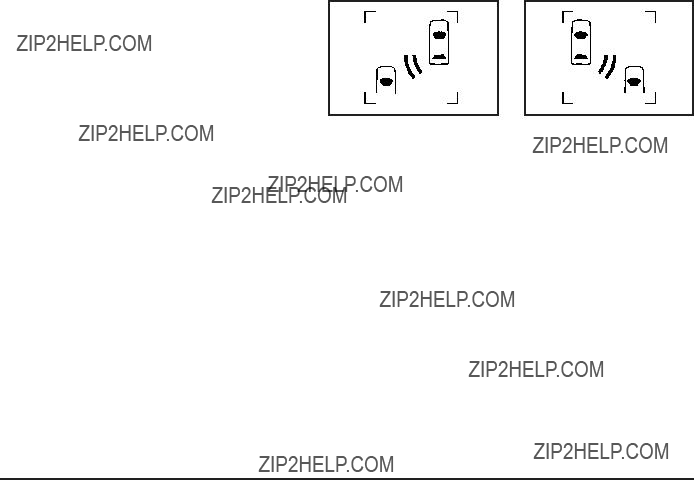
SBZA Detection Zones
The SBZA sensor covers a zone of approximately one lane over from both sides of the vehicle, 11 ft. or
3.5 m. This zone starts at each side mirror and goes back approximately 16 ft. (5.0 m). The height of the zone is approximately between 1.5 ft. (0.5 m) and 6 ft. (2.0 m) off the ground.
Use caution while changing lanes when towing a trailer, as the SBZA detection zones do not change when a trailer is towed.
How the System Works
When the vehicle is started, both outside mirror displays will brie???y come on to indicate that the system is operating. When the vehicle is moving forward, the left or right side mirror SBZA display will light up if a vehicle is detected in that blind zone. If the turn signal is activated and a vehicle is also detected on the same side, the SBZA display will ???ash to give you extra warning not to change lanes.
SBZA displays do not come on while the vehicle is approaching or passing other vehicles. At speeds greater then 20 mph (32 km/h), SBZA displays may come on when a vehicle you have passed remains in or drops back into the detection zone.
SBZA can be disabled through the Driver Information Center (DIC). See Driver Information Center (DIC) on page
is disabled by the driver, the SBZA mirror displays will not light up during normal driving.
When the System Does Not Seem To Work
Properly
Occasional missed alerts can occur under normal circumstances and will increase in wet conditions. The system does not need to be serviced due to an occasional missed alert. The number of missed
alerts will increase with increased rainfall or road spray.
If the SBZA displays do not light up when the system is on and vehicles are in the blind zone, the system may need service. Take the vehicle to your dealer/retailer.
SBZA is designed to ignore stationary objects; however, the system may occasionally light up due to guard rails, signs, trees, shrubs, and other stationary objects. This is normal system operation, the vehicle does
not need service.
SBZA does not operate when the left or right corners of the rear bumper are covered with mud, dirt, snow, ice, slush, or in heavy rainstorms. For cleaning instructions, see Washing Your Vehicle on page
The SBZA displays may remain on if a trailer is attached to the vehicle, or a bicycle or object is extending out
to either side of the vehicle.
When SBZA is disabled for any reason other than the driver turning it off, the driver will not be able to turn SBZA back on using the DIC. The SIDE BLIND ZONE ALERT ON option will not be selectable if the conditions for normal system operation are not met. Until normal operating conditions for SBZA are met, you should not rely upon SBZA while driving.
SBZA Error Messages
The following messages may appear in the DIC:
SIDE BLIND ZONE ALERT SYSTEM OFF: This message indicates that the driver has turned the system off.
SIDE BLIND ZONE SYS. UNAVAILABLE: This message indicates that the SBZA system is disabled either because the sensor is blocked and cannot detect vehicles in your blind zone, or the vehicle is passing through an open ???eld of view area, such as the desert, where there is insufficient data for operation. The sensor may be blocked by mud, dirt, snow, ice, slush, or even heavy rainstorms. This message may also activate during heavy rain or due to road spray. The vehicle does not need service. For cleaning, see Washing Your Vehicle on page
SERVICE SIDE BLIND ZONE ALERT SYSTEM: If this message appears, both SBZA displays will remain on indicating there is a problem with the SBZA system.
If these displays remain on after continued driving, the system needs service. Take the vehicle to your dealer/retailer.
Rear Vision Camera (RVC)
This vehicle may have a Rear Vision Camera system. Read this entire section before using it.
{ CAUTION:
The Rear Vision Camera (RVC) system does not replace driver vision. RVC does not:
???Detect objects that are outside the camera???s ???eld of view, below the bumper, or underneath the vehicle.
???Detect children, pedestrians, bicyclists, or pets.
Do not back the vehicle by only looking at the rear vision camera screen, or use the screen during longer, higher speed backing maneuvers or where there could be
So if you do not use proper care before backing up, you could hit a vehicle, child, pedestrian, bicyclist, or pet, resulting in vehicle damage, injury, or death. Even though the vehicle has the RVC system, always check carefully before backing up by checking behind and around the vehicle.
Vehicles Without Navigation System
The rear vision camera system is designed to help the driver when backing up by displaying a view of the area behind the vehicle. When the key is in the ON/RUN position and the driver shifts the vehicle into R (Reverse), the video image automatically appears on the inside rear view mirror. Once the driver shifts out of R (Reverse), the video image automatically disappears from the inside rear view mirror.
Turning the Rear Vision Camera System Off or On
To turn off the rear vision camera system, press and hold z , located on the inside rearview mirror, until the left indicator light turns off. The rear camera vision display is now disabled.
To turn the rear vision camera system on again, press and hold z until the left indicator light illuminates. The rear vision camera system display is now enabled and the display will appear in the mirror normally.
Vehicles With Navigation System
The rear vision camera system is designed to help the driver when backing up by displaying a view of the area behind the vehicle. When the driver shifts
the vehicle into R (Reverse), the video image automatically appears on the navigation screen. Once the driver shifts out of R (Reverse), the navigation screen will go back to the last screen that had been displayed, after a delay.
Turning the Rear Vision Camera System On or Off
To turn the rear vision camera system on or off:
1.Shift into P (Park).
2.Press the MENU button to enter the con???gure menu options, then press the MENU hard key
to select Display or touch the Display screen button.
3.Select the Rear Camera Options screen button. The Rear Camera Options screen will display.
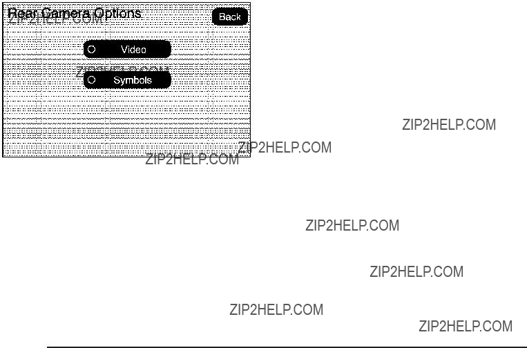
Adjusting the Brightness and Contrast of
the Screen
To adjust the brightness and contrast of the screen, press the MENU button while the rear vision camera image is on the display. Any adjustments made will only affect the rear vision camera screen.
] (Brightness): Touch the + (plus) or ??? (minus) screen buttons to increase or decrease the brightness of the screen.
_ (Contrast): Touch the + (plus) or ??? (minus) screen buttons to increase or decrease the contrast of the screen.
4.Select the Video screen button. When the Video screen button is highlighted the RVC system is on.
The delay that is received after shifting out of
R (Reverse) is approximately 10 seconds. The delay can be cancelled by performing one of the following:
???Pressing a hard key on the navigation system.
???Shifting in to P (Park).
???Reach a vehicle speed of 5 mph (8 km/h).
There is a message on the rear vision camera screen that states ???Check Surroundings for Safety???.
Symbols
The navigation system may have a feature that lets the driver view symbols on the navigation screen while using the rear vision camera. The Ultrasonic Rear Park Assist (URPA) system must not be disabled to use the caution symbols. If URPA has been disabled and the symbols have been turned on, the Rear Parking Assist Symbols Unavailable error message may display. See Ultrasonic Rear Parking Assist (URPA) on page
The symbols appear when an object has been detected by the URPA system. The symbol may cover the object when viewing the navigation screen.
To turn the symbols on or off:
1.Make sure that URPA has not been disabled.
2.Shift into P (Park).
3.Press the MENU hard key to enter the con???gure menu options, then press the MENU hard key repeatedly until Display is selected or touch
the Display screen button.
4.Select the Rear Camera Options screen button. The Rear Camera Options screen will display.
5.Touch the Symbols screen button. The screen button will be highlighted when on.
Rear Vision Camera Error Messages
Service Rear Vision Camera System: This message can display when the system is not receiving information it requires from other vehicle systems.
If any other problem occurs or if a problem persists, see your dealer/retailer.
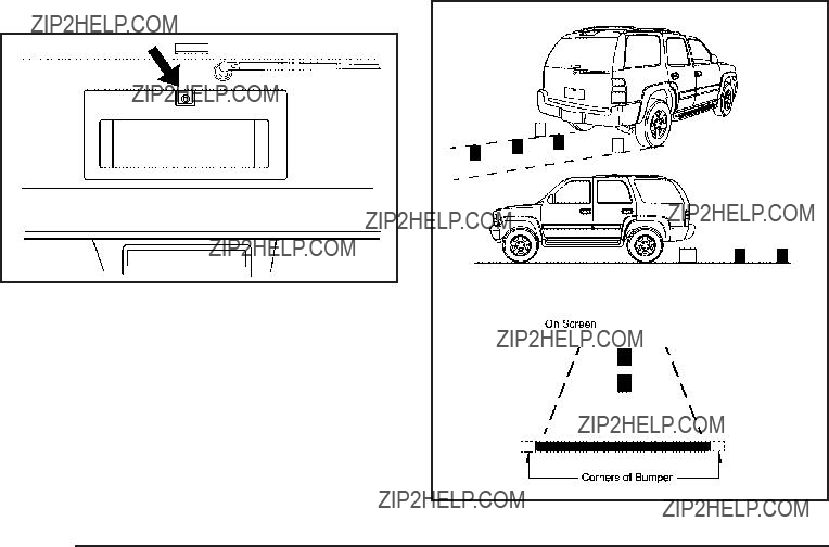
Rear Vision Camera Location
The image is provided by the camera located above the license plate.
The camera uses a special lens. The distance of the image that appears on the screen differs from the actual distance. The area displayed by the camera is limited. The camera does not display objects which are close
to either corner of the bumper or under the bumper. The area displayed on the screen can vary according to vehicle orientation or road conditions.
The following illustration shows the ???eld of view that the camera provides.

When the System Does Not Seem To
Work Properly
The rear vision camera system might not work properly or display a clear image if:
???The RVC is turned off. See ???Turning the Rear Camera System On or Off??? earlier in this section.
???It is dark.
???The sun or the beam of headlights is shining directly into the camera lens.
???Ice, snow, mud, or anything else builds up on the camera lens. Clean the lens, rinse it with water, and wipe it with a soft cloth.
???The back of the vehicle is in an accident, the position and mounting angle of the camera
can change or the camera can be affected. Be sure to have the camera and its position and mounting angle checked at your dealer/retailer.
???There are extreme temperature changes.
The rear vision camera system display in the rearview mirror may turn off or not appear as expected due to one of the following conditions. If this occurs the
left indicator light on the mirror will ???ash.
???A slow ???ash may indicate a loss of video signal, or no video signal present during the reverse cycle.
???A fast ???ash may indicate that the display has been on for the maximum allowable time during a reverse cycle, or the display has reached an Over Temperature limit.
The fast ???ash conditions are used to protect the video device from high temperature conditions. Once conditions return to normal the device will reset and the green indicator will stop ???ashing.
During any of these fault conditions, the display will be blank and the indicator will continue to ???ash as long as the vehicle is in R (Reverse) or until the conditions return to normal.
Pressing and holding z when the left indicator light is ???ashing will turn off the video display along with the left indicator light.
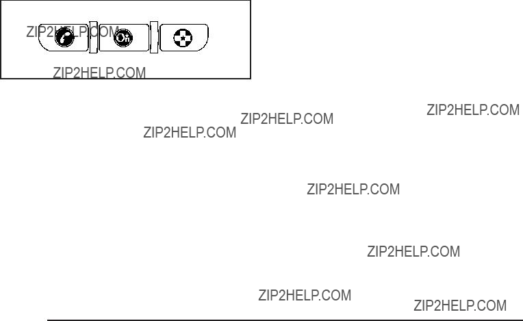
OnStar?? System
OnStar uses several innovative technologies and live advisors to provide a wide range of safety, security, information, and convenience services. If the airbags deploy, the system is designed to make an automatic call to OnStar Emergency advisors who can request emergency services be sent to your location. If the keys are locked in the vehicle, call OnStar at
for 60 days, is available on most vehicles. OnStar
OnStar service is provided subject to the OnStar Terms and Conditions included in the OnStar Subscriber glove box literature.
Some services such as Remote Door Unlock or Stolen Vehicle Location Assistance may not be available until the owner of the vehicle registers with OnStar. After the ???rst prepaid year, contact OnStar to select a monthly or annual subscription payment plan. If a payment plan is not selected, the OnStar system and all services, including airbag noti???cation and emergency services, may be deactivated and no longer available. For more information visit onstar.com (U.S.) or onstar.ca (Canada), or press the OnStar button to speak with an advisor.
Not all OnStar services are available on all vehicles. To check if this vehicle is able to provide the services described below, or for a full description of OnStar services and system limitations, see the OnStar Owner???s Guide in the glove box or visit onstar.com (U.S.) or onstar.ca (Canada), contact OnStar at
the OnStar button to speak with an OnStar advisor 24 hours a day, 7 days a week.

OnStar Services Available with the Safe & Sound Plan
???Automatic Noti???cation of Airbag Deployment
???Advanced Automatic Crash Noti???cation (AACN) (If equipped)
???Link to Emergency Services
???Roadside Assistance
???Stolen Vehicle Location Assistance
???Remote Door Unlock/Vehicle Alert
???OnStar Vehicle Diagnostic Email
???GM Goodwrench On Demand Diagnostics
???OnStar
???OnStar Virtual Advisor (U.S. Only)
OnStar Services Included with Directions & Connections Plan
???All Safe and Sound Plan Services
???OnStar
???RideAssist
???Information and Convenience Services
OnStar
OnStar
on eligibility. To ???nd out more, refer to the OnStar Owner???s Guide in the vehicle???s glove box, visit onstar.com or onstar.ca, or speak with an OnStar advisor by pressing the OnStar button or calling
OnStar
Vehicles with the OnStar

OnStar Virtual Advisor
OnStar Virtual Advisor is a feature of OnStar
OnStar Steering Wheel Controls
This vehicle may have a Talk/Mute button that can be used to interact with OnStar
On some vehicles, the mute button can be used to dial numbers into voice mail systems, or to dial phone extensions. See the OnStar Owner???s Guide for more information.
How OnStar Service Works
The OnStar system can record and transmit vehicle information. This information is automatically sent to an OnStar Call Center when the OnStar button is pressed, the emergency button is pressed, or if the airbags or AACN system deploy. This information usually includes the vehicle???s GPS location and, in the event of a crash, additional information regarding the crash that the vehicle was involved in (e.g. the direction from which the vehicle was hit). When the Virtual Advisor feature of OnStar
OnStar service cannot work unless the vehicle is in a place where OnStar has an agreement with a wireless service provider for service in that area. OnStar service also cannot work unless the vehicle is in a place where the wireless service provider OnStar has hired for that area has coverage, network capacity and reception when the service is needed, and technology that is compatible with the OnStar service. Not all services are available everywhere, particularly in remote or enclosed areas, or at all times.
Location information about the vehicle is only available if the GPS satellite signals are unobstructed and available.

The vehicle must have a working electrical system, including adequate battery power, for the OnStar equipment to operate. There are other problems OnStar cannot control that may prevent OnStar from providing OnStar service at any particular time or place. Some examples are damage to important parts of the vehicle in a crash, hills, tall buildings, tunnels, weather or wireless phone network congestion.
Your Responsibility
Increase the volume of the radio if the OnStar advisor cannot be heard. If the light next to the OnStar buttons is red, the system may not be functioning properly. Press the OnStar button and request a vehicle diagnostic. If the light appears clear (no light is appearing), your OnStar subscription has expired and all services have been deactivated. Press the OnStar button to con???rm that the OnStar equipment is active.
Universal Home Remote
System
The Universal Home Remote System provides a way to replace up to three
This device complies with Part 15 of the FCC Rules. Operation is subject to the following two conditions:
1.This device may not cause harmful interference.
2.This device must accept any interference received, including interference that may cause undesired operation.
This device complies with
1.This device may not cause interference.
2.This device must accept any interference received, including interference that may cause undesired operation of the device.
Changes or modi???cations to this system by other than an authorized service facility could void authorization to use this equipment.
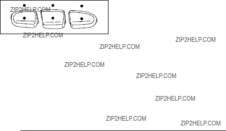
Universal Home Remote System
Operation (With Three Round LED)
This vehicle may have the Universal Home Remote System. If there are three round Light Emitting Diode (LED) indicator lights above the Universal Home Remote buttons, follow the instructions below.
This system provides a way to replace up to three remote control transmitters used to activate devices such as garage door openers, security systems, and home automation devices.
Do not use this system with any garage door opener that does not have the stop and reverse feature. This includes any garage door opener model manufactured before April 1, 1982.
Read the instructions completely before attempting to program the transmitter. Because of the steps involved, it may be helpful to have another person assist with programming the transmitter.
Be sure to keep the original remote control transmitter for use in other vehicles, as well as, for future programming. Only the original remote control transmitter is needed for Fixed Code programming. The programmed buttons should be erased when the vehicle is sold or the lease ends. See ???Erasing Universal Home Remote Buttons??? later in this section.
Park the vehicle outside of the garage when programming a garage door. Be sure that people and objects are clear of the garage door or gate that is being programmed.
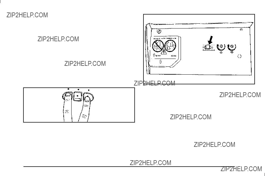
Programming Universal Home
Remote ??? Rolling Code
For questions or help programming the Universal Home Remote System, call
Most garage door openers sold after 1996 are Rolling Code units.
Programming a garage door opener involves
To program up to three devices:
1.From inside the vehicle, press the two outside buttons at the same time for one to two seconds, and immediately release them.
2.Locate in the garage, the garage door opener receiver
or ???Smart??? button. It can usually be found where the hanging antenna wire is attached to the
3.Immediately return to the vehicle. Press and hold the Universal Home Remote button that will be used to control the garage door until the garage door moves. The indicator light, above the selected button, should slowly blink. This button may
need to be held for up to 20 seconds.
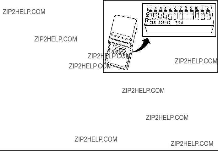
4.Immediately, within one second, release the button when the garage door moves. The indicator light will blink rapidly until programming is complete.
5.Press and release the same button again. The garage door should move, con???rming that programming is successful and complete.
To program another Rolling Code device such as an additional garage door opener, a security device,
or home automation device, repeat Steps 1 through 5, choosing a different function button in Step 3 than what was used for the garage door opener.
If these instructions do not work, the garage door opener is probably a Fixed Code unit. Follow the Programming instructions that follow for a Fixed Code garage door opener.
Programming Universal Home
Remote ??? Fixed Code
For questions or help programming the Universal Home Remote System, call
Most garage door openers sold before 1996 are Fixed Code units.
Programming a garage door opener involves
To program up to three devices:
1.To verify that the garage door opener is a Fixed Code unit, remove the battery cover on the hand held transmitter supplied by the manufacturer of the garage door opener motor. If there are a row of dip switches similar to the graphic above, the garage door opener is a Fixed Code unit. If you do not
see a row of dip switches, return to the previous section for Programming Universal Home Remote ??? Rolling Code.
Your hand held transmitter can have between eight to 12 dip switches depending on the brand of transmitter.
The garage door opener receiver (motor head unit) could also have a row of dip switches that can be used when programming the Universal Home Remote. If the total number of switches on the motor head and hand held transmitter are different, or if the dip switch settings are different, use the dip switch settings on the motor head unit to program the Universal Home Remote. The motor head dip switch settings can also be used when the original hand held transmitter is not available.
Example of Eight Dip Switches with Two Positions
Example of Eight Dip Switches with Three Positions
The panel of switches might not appear exactly as they do in the examples above, but they should be similar.
The switch positions on the
???A switch in the up position could be labeled as ???Up,??? ???+,??? or ???On.???
???A switch in the down position could be labeled as ???Down,??? ??????,??? or ???Off.???
???A switch in the middle position could be labeled as ???Middle,??? ???0,??? or ???Neutral.???

2.Write down the eight to 12 switch settings from left to right as follows:
???When a switch is in the up position, write ???Left.???
???When a switch is in the down position, write ???Right.???
???If a switch is set between the up and down position, write ???Middle.???
The switch settings written down in Step 2 now become the button strokes to be entered into the Universal Home Remote in Step 4. Be sure to enter the switch settings written down in Step 2, in order from left to right, into the Universal Home Remote, when completing Step 4.
3.From inside your vehicle, ???rst ???rmly press all three buttons at the same time for about three seconds. Release the buttons to put the Universal Home Remote into programming mode.
4.The indicator lights will blink slowly. Enter each switch setting from Step 2 into your vehicle???s Universal Home Remote. You will have two and
???If you wrote ???Left,??? press the left button in the vehicle.
???If you wrote ???Right,??? press the right button in the vehicle.
???If you wrote ???Middle,??? press the middle button in the vehicle.

5.After entering all of the switch positions, again, ???rmly press and release all three buttons at the same time. The indicator lights will turn on.
6.Press and hold the button that will be used to control the garage door until the garage door moves. The indicator light above the selected button should slowly blink. This button may need to be held for up to 55 seconds.
7.Immediately release the button when the garage door moves. The indicator light will blink rapidly until programming is complete.
8.Press and release the same button again. The garage door should move, con???rming that programming is successful and complete.
To program another Fixed Code device such as an additional garage door opener, a security device,
or home automation device, repeat Steps
the garage door opener.
Using Universal Home Remote
Press and hold the appropriate button for at least
half of a second. The indicator light will come on while the signal is being transmitted.
Reprogramming Universal Home
Remote Buttons
Any of the three buttons can be reprogrammed by repeating the instructions.
Erasing Universal Home Remote
Buttons
The programmed buttons should be erased when the vehicle is sold or the lease ends.
To erase either Rolling Code or Fixed Code on the Universal Home Remote device:
1.Press and hold the two outside buttons at the same time for approximately 20 seconds, until the indicator lights, located directly above the buttons, begin to blink rapidly.
2.Once the indicator lights begin to blink, release both buttons. The codes from all buttons will be erased.
For help or information on the Universal Home Remote System, call the customer assistance phone number under Customer Assistance Offices on page
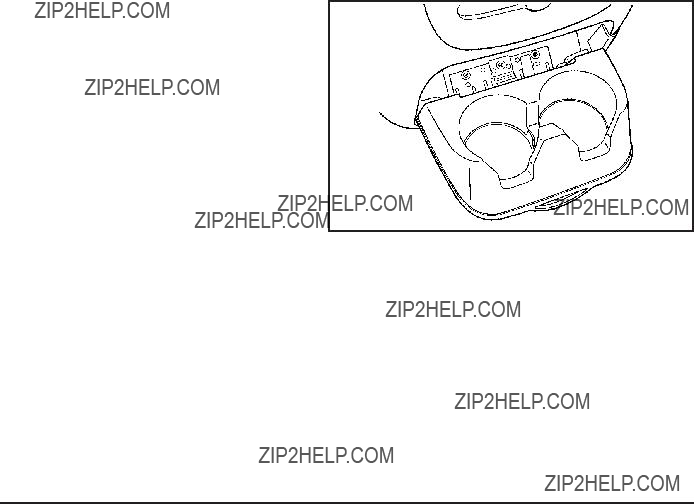
Storage Areas
Glove Box
Lift up on the glove box lever to open it.
Cupholders
For vehicles with cupholders located in the front and rear of the ???oor console or in the fold down armrest, adjust the front cupholders by moving the insert forward or rearward.
Pull downward on the lid to access the rear ???oor console cupholders.
There could also be cupholders located in the second and third row seat armrest areas.

Center Console Storage
For vehicles with a console compartment, it is located between the bucket seats.
Press the button and lift the lid to access the console compartment.
A cupholder located in the rear of the console, swings down for the rear seat passenger to use.
Luggage Carrier
Notice: Loading cargo on the luggage carrier that weighs more than 200 lbs (91 kg) or hangs over the rear or sides of the vehicle can damage the vehicle.
Load cargo so that it rests on the slats as far forward as possible and against the side rails, making sure to fasten it securely.
For vehicles with a luggage carrier, items can be loaded on top of the vehicle.
The luggage carrier has siderails attached to the roof. It can also have crossrails which can be moved
back and forth to help secure cargo. Tie the load to the siderails or siderail supports.
Do not exceed the maximum vehicle capacity when loading the vehicle. For more information on vehicle capacity and loading, see Loading the Vehicle on page
Make sure the cargo is properly loaded.
To prevent damage or loss of cargo while driving, periodically stop and check to make sure cargo is still securely fastened.
???If small heavy objects are placed on the roof, cut a piece of 3/8 inch plywood to ???t inside the crossrails and siderails to spread the load. Tie the plywood to the siderail supports.
???Tie the load and secure it to the crossrails or the siderail supports. Use the crossrails only to keep the load from sliding. To move a crossrail, lift the release lever up, on both sides of the rail. Then slide the crossrail to the desired position balancing the force side to side. Press the release lever down on both sides of the rail, down to tighten it. Try to slide the crossrail back and forth slightly to make sure it is tight.
???To carry long items, move the crossrails as far apart as possible. Tie the load to the crossrails and the siderails or siderail supports. Also tie the load to the bumpers, but do not tie the load so tightly that the crossrails or siderails are damaged.
???After moving a crossrail, be sure it is securely locked into the siderail.
A Center
Make sure items loaded on the roof of the vehicle do not block or damage the CHMSL.

Rear Storage Area
For vehicles with a rear storage area, it is located in the rear cargo area of the vehicle on the driver???s side trim panel.
Turn the knobs and swing the storage door to access the storage compartment. The door can be removed.
Rear Seat Armrest
For vehicle with a rear seat armrest, pull the loop at the top of the armrest down to access the cupholders.
Cargo Cover
{ CAUTION:
An improperly stored cargo cover could be thrown about the vehicle during a collision or sudden maneuver. Someone could be injured. If the cover is removed, always store it in the proper storage location. When it is replaced, always be sure that it is securely reattached.
To use the cover, for vehicles that have it:
1.Pull the cover handle toward the rear of the vehicle.
2.Latch the cover posts into the retaining sockets on the cargo area trim panels.
To return the cover to the retracted position:
1.Pull up on the cover handle to release the cover posts from the retaining sockets.
2.Let the cover move forward to the full retracted position.
To remove the cover, from a regular wheelbase model:
1.Let the cover go all the way into the holder.
2.Then, grasping the driver???s side cover end cap, push the cover end cap toward the passenger side of the vehicle.
3.Swing the cover rearward and take it out of the vehicle.

To put the cover in the vehicle:
1.Make sure the cover slot in the holder faces rearward with the round surface facing down.
2.Then, hold the cover at an angle and place the cover end cap into the slot in the passenger side trim panel.
3.Move the other end of the cover forward and hold it next to the driver???s side trim panel slot.
4.Press the end caps in, to allow the cover to ???t into the trim slot.
5.Pull lightly on the cover holder to make sure it is secure.
On extended wheelbase models there are two cover positions. The slots furthest forward allow the cover to be used if the third seat is removed or folded down. The cover can be installed and removed from either side.
Sunroof
Your vehicle may be equipped with a power sliding sunroof. To open or close the sunroof, the ignition needs to be turned to ON/RUN, or Retained Accessory Power (RAP) must be active. When RAP is active, the sunroof will work for 10 minutes after the ignition is turned off, or until a front door is opened. See Retained Accessory Power (RAP) on page
There are two switches in the overhead console that operate the sunroof.

The sunroof has a comfort stop feature which stops the sunroof from opening to the
When the sunroof is opened, an air de???ector will automatically raise. The air de???ector will retract when the sunroof is closed.
The sunroof has a comfort stop feature which stops the sunroof from opening to the
When the sunroof is opened, an air de???ector will automatically raise. The air de???ector will retract when the sunroof is closed.
Vent: The sunroof has an
the passenger???s side switch to vent the sunroof. To stop the sunroof partway, press the switch a second time. To close the sunroof, press and hold the front of the passenger???s side switch. To stop the sunroof partway, release the switch.
Do not keep the sunroof open for long periods of time while the vehicle is not in use. Debris can collect in the tracks, damage the sunroof operation and plug the water draining system.
Section 3 Instrument Panel

Section 3 Instrument Panel
??? NOTES

Instrument Panel Overview
United States version shown; Canada similar

The main components of the instrument panel are the following:
A.Outlet Adjustment on page
B.Turn Signal/Multifunction Lever on page
C.Instrument Panel Cluster on page
D.Hazard Warning Flashers on page
E.Shift Lever. See Automatic Transmission Operation on page
F.Tow/Haul Mode on page
G.Driver Information Center (DIC) on page
H.Audio System(s) on page
I.Exterior Lamps on page
J.Dome Lamp Override on page
K.Hood Release on page
L.Integrated Trailer Brake Controller (If Equipped).
Towing a Trailer on page
M.Automatic Transfer Case Control. (If Equipped). See
N.Cruise Control on page
O.Tilt Wheel on page
P.Horn on page
Q.Audio Steering Wheel Controls on page
R.Climate Control System on page
(If Equipped).
S.Accessory Power Outlet(s) on page
T.StabiliTrak?? System on page
(If Equipped). Heated Windshield Washer Fluid Button (If Equipped). See Windshield Washer on page
(If Equipped).
U.Glove Box on page
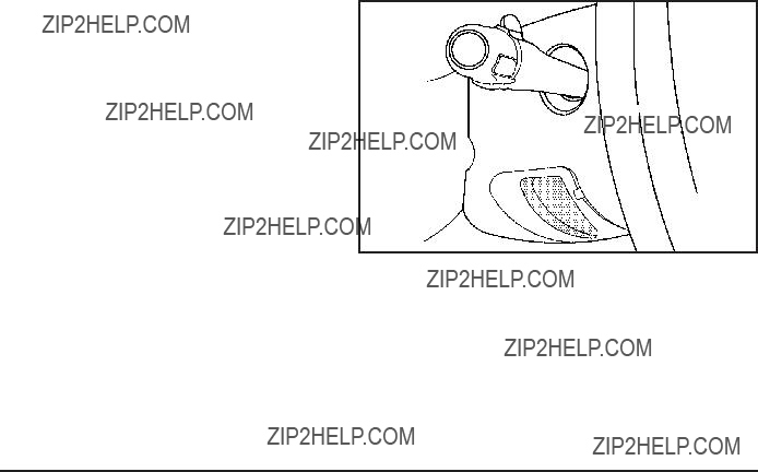
Hazard Warning Flashers
| (Hazard Warning Flasher): Press this button located on top of the steering column, to make the front and rear turn signal lamps ???ash on and off. This
warns others that you are having trouble. Press again to turn the ???ashers off.
When the hazard warning ???ashers are on, the vehicle???s turn signals will not work.
Horn
To sound the horn, press the center pad on the steering wheel.
Tilt Wheel
The vehicle has a tilt wheel that lets the steering wheel be adjusted.
The tilt steering wheel lever is located on the lower left side of the column.
To tilt the wheel, hold the steering wheel and pull the lever. Then move the steering wheel to a comfortable position and release the lever to lock the wheel in place.
Do not adjust the steering wheel while driving.

Turn Signal/Multifunction Lever
The lever on the left side of the steering column includes the following:
G : Turn and Lane Change Signals
5 3 : Headlamp
N : Windshield Wipers
L : Windshield Washer
5 : Rear Wiper Delay
Z : Rear Wiper
= : Rear Wiper Wash
Information for these features is on the pages following.
Turn and
An arrow on the instrument panel cluster ???ashes in the direction of the turn or lane change.
Move the lever all the way up or down to signal a turn.
Raise or lower the lever for less than one second until the arrow starts to ???ash to signal a lane change. This causes the turn signals to automatically ???ash three times. It will ???ash six times if
the lever.
The lever returns to its starting position whenever it is released.

If after signaling a turn or a lane change the arrows ???ash rapidly or do not come on, a signal bulb could be burned out.
Have the bulbs replaced. If the bulb is not burned out, check the fuse. See Fuses and Circuit Breakers on page
Turn Signal On Chime
If the turn signal is left on for more than 3/4 of a mile (1.2 km), a chime will sound at each ???ash of the turn signal and the message TURN SIGNAL ON will
also appear in the Driver Information Control (DIC). To turn the chime and message off, move the turn
signal lever to the off position.
Headlamp
5 3 (Headlamp High/Low Beam Changer): To change the headlamps from low to high beam, push the lever toward the instrument panel. To return
to
When the high beams are on, this indicator light on the instrument panel cluster will also be on.
This feature lets you use the
It works even if the headlamps are in the automatic position.
To use it, pull the turn signal lever toward you, then release it.
If the headlamps are in the automatic position or on low beam, the
will stay on as long as you hold the lever toward you. The

Windshield Wipers
Turn the band with the wiper symbol to control the windshield wipers.
8 (Mist): Turn to mist for a single wiping cycle. Hold it there until the wipers start. Then let go. The wipers stop after one wipe. Hold the band on mist longer, for more wipe cycles.
9 (Off): Turns the wipers off.
6(Delay): Turn the band to adjust the delay time. The delay between wiping cycles becomes shorter as
the band is moved to the top of the lever. This can be very useful in light rain or snow.
6(Low Speed): For steady wiping at low speed.
? (High Speed): For
Clear ice and snow from the wiper blades before using them. If they are frozen to the windshield, gently loosen or thaw them. Damaged wiper blades may not clear the windshield well, making it harder to see
and drive safely. If the blades do become damaged, install new blades or blade inserts. For more information, see Windshield Wiper Blade Replacement on page
Heavy snow or ice can overload the wiper motor. A circuit breaker will stop the motor until it cools down. Clear away snow or ice to prevent an overload.
Rainsense??? II Wipers
For vehicles with Rainsense??? II windshield wipers, the moisture sensor is located next to the inside rearview mirror and is mounted on the windshield. When active, these sensors are able to detect moisture on the windshield and automatically turn on the wipers.
To turn on the Rainsense feature, the wipers must be set to one of the ???ve delay settings on the multifunction lever. Each of the ???ve settings adjusts the sensitivity
of the sensor.
Since different drivers have different setting preferences, it is recommended that the
The sensor will automatically control the frequency of the wipes from the off setting to the high speed setting according to the weather conditions. The wipers can be left in a rainsense mode even when it is not raining.

When Rainsense is active, the headlamps will turn on automatically if the exterior lamp control is in the AUTO position and the wipers are active.
Notice: Going through an automatic car wash with the wipers on can damage them. Turn the wipers off when going through an automatic car wash.
Windshield Washer
{ CAUTION:
In freezing weather, do not use your washer until the windshield is warmed. Otherwise the washer ???uid can form ice on the windshield, blocking your vision.
L (Washer Fluid): Push the paddle marked with the windshield washer symbol at the top of the multifunction lever, to spray washer ???uid on the windshield. The wipers clear the window and then either stop or return to the preset speed.
Heated Windshield Washer
For vehicles with the heated windshield washer ???uid system it can be used to help clear ice, snow, tree sap, or bugs from the windshield.
_ (Heated Washer Fluid): Press the heated washer ???uid button to activate the heated windshield washer ???uid system. This activation initiates four heated wash/wipe cycles. The ???rst heated wash/wipe cycle may take up to 40 seconds to occur, depending on outside temperature. After the ???rst wash/wipe cycle, it may take up to 20 seconds for each of the remaining cycles to begin. Press the button again to turn off the heated windshield washer ???uid system or it will automatically turn off after four wipe cycles have been completed.
When the heated windshield washer ???uid system is activated under certain outside temperature
conditions, steam may ???ow out of the washer nozzles for a short period of time before washer ???uid is sprayed. This is a normal condition.
HEATING WASH FLUID WASH WIPES PENDING is displayed on the DIC when the washer system is heating the ???uid. WASHER FLUID LOW ADD FLUID is displayed when the washer ???uid is low. See DIC Warnings and Messages on page

Rear Window Wiper/Washer
{ CAUTION:
In freezing weather, do not use your washer until the windshield is warmed. Otherwise the washer ???uid can form ice on the windshield, blocking your vision.
The rear wiper control is located on the turn signal/multifunction lever.
To turn the rear wiper on, slide the lever to a wiper position.
9 (Off): Turns the wiper off.
5 (Rear Wiper Delay): Turns on the rear wiper delay.
Z (Rear Wiper): Turns on the rear wiper.
= (Rear Wiper Wash): To turn on the rear wiper wash, push the button on the end of the turn signal/multifunction lever to spray washer ???uid on the rear window. The wipers will clear the rear window and either stop or return to your preset speed. For more washer cycles, press and hold the button.
The rear window wiper/washer will not operate if the liftgate or liftglass is open or ajar. If the liftgate or liftglass is opened while the rear wiper is on, the wiper will return to the parked position and stop.

Cruise Control
{ CAUTION:
Cruise control can be dangerous where you cannot drive safely at a steady speed. So, do not use the cruise control on winding roads or in heavy traffic.
Cruise control can be dangerous on slippery roads. On such roads, fast changes in tire traction can cause excessive wheel slip, and you could lose control. Do not use cruise control on slippery roads.
With cruise control, a speed of about 25 mph (40 km/h) or more can be maintained without keeping your foot on the accelerator. Cruise control does not work
at speeds below about 25 mph (40 km/h).
When the brakes are applied, cruise control is turned off.
If the vehicle has StabiliTrak??, and the system begins to limit wheel spin, cruise control will automatically disengage. See StabiliTrak?? System on page
The cruise control buttons are located on left side of the steering wheel.
T (On/Off): This button can both activate and turn off the system. The indicator light on the button turns on when cruise control is on and turns off when cruise control is off.
+ RES (Resume/Accelerate): Press to make the vehicle accelerate or resume to a previously set speed.
SET ??? (Set/Coast): Press to set the speed or make the vehicle decelerate.
[ (Cancel): Press to cancel cruise control without erasing the set speed from memory.
Setting Cruise Control
Cruise control will not work if the parking brake is set, or if the master cylinder brake ???uid level is low.
The cruise control light on the instrument panel cluster comes on after the cruise control has been set to
the desired speed.
{ CAUTION:
If you leave your cruise control on when you are not using cruise, you might hit a button and go into cruise when you do not want to. You could be startled and even lose control. Keep the cruise control switch off until you want to use cruise control.
1.Press the I button.
2.Get up to the desired speed.
3.Press the SET??? button located on the steering wheel and release it.
4.Take your foot off the accelerator.
Resuming a Set Speed
If the cruise control is set at a desired speed and then the brakes are applied, this shuts off the cruise control. But it does not need to be reset.
Once the vehicle speed reaches about 25 mph (40 km/h) or more, press the +RES button on the steering wheel. The vehicle returns to the previously set speed and stays there.
Increasing Speed While Using Cruise
Control
To increase the cruise speed while using cruise control:
???Press and hold the +RES button on the steering wheel until the desired speed is reached, then release it.
???To increase vehicle speed in small increments, press the +RES button. Each time this is done, the vehicle goes about 1 mph (1.6 km/h) faster.

Reducing Speed While Using Cruise
Control
To reduce the vehicle speed while using cruise control:
???Press and hold the SET??? button on the steering wheel until the desired lower speed is reached, then release it.
???To slow down in very small amounts, press the SET??? button on the steering wheel brie???y. Each time this is done, the vehicle goes about 1 mph (1.6 km/h) slower.
Passing Another Vehicle While Using
Cruise Control
Use the accelerator pedal to increase the vehicle speed. When you take your foot off the pedal, the vehicle will slow down to the previous set cruise speed.
Using Cruise Control on Hills
How well the cruise control will work on hills depends upon the vehicle speed, load, and the steepness of the hills. When going up steep hills, you might have to step on the accelerator pedal to maintain the vehicle???s speed. When going downhill, you might have to brake or shift to a lower gear to keep the vehicle???s speed
down. When the brakes are applied the cruise control turns off.
Ending Cruise Control
There are three ways to end cruise control:
???Step lightly on the brake pedal.
???Press the [ button on the steering wheel.
???Press the I button on the steering wheel.
Erasing Speed Memory
The cruise control set speed memory is erased when the cruise control or the ignition is turned off.
Exterior Lamps
The exterior lamps control is located on the instrument panel to the left of the steering wheel.
It controls the following systems:
???Headlamps
???Taillamps
???Parking Lamps

???License Plate Lamps
???Instrument Panel Lights
The exterior lamps control has four positions:
O (Off): Turns off the automatic headlamps and daytime running lamps (DRL). Turning the headlamp control to the off position again will turn the automatic headlamps or DRL back on.
For vehicles ???rst sold in Canada, the off position will only work for vehicles that are shifted into the P (Park) position.
AUTO (Automatic): Automatically turns on the headlamps at normal brightness, together with the following:
???Parking Lamps
???Instrument Panel Lights
???Taillamps
???License Plate Lamps
; (Parking Lamps): Turns on the parking lamps together with the following:
???Instrument Panel Lights
???Taillamps
???License Plate Lamps
2 (Headlamps): Turns on the headlamps together with the following lamps listed below.
???Parking Lamps
???Instrument Panel Lights
???Taillamps
???License Plate Lamps
When the headlamps are turned on while the vehicle is on, the headlamps will turn off automatically 10 minutes after the ignition is turned off. When the headlamps are turned on while the vehicle is off, the headlamps will stay on for 10 minutes before automatically turning off to prevent the battery from being drained. Turn the headlamp control to off and then back to the headlamp on position to make the headlamps stay on for an additional 10 minutes.
Headlamps on Reminder
A reminder chime will sound when the headlamps or parking lamps are manually turned on and the ignition is off and a door is open. To disable the chime, turn the light off.

Daytime Running Lamps (DRL)
Daytime Running Lamps (DRL) can make it easier for others to see the front of your vehicle during the
day. Fully functional daytime running lamps are required on all vehicles ???rst sold in Canada.
The DRL system will come on when the following conditions are met:
???The ignition is on.
???The exterior lamps control is in AUTO.
???The transmission is not in P (Park).
???The light sensor determines it is daytime.
When the DRL are on, only the DRL lamps will be on. The taillamps, sidemarker, instrument panel lights, and other lamps will not be on.
When it begins to get dark, the automatic headlamp system will switch from DRL to the headlamps.
To turn off the DRL lamps, turn the exterior lamps control to the OFF position and then release. For vehicles ???rst sold in Canada, the transmission must be in the P (Park) position, before the DRL lamps can
be turned off.
Automatic Headlamp System
When it is dark enough outside, the automatic headlamp system turns on the headlamps at the normal brightness, along with the taillamps, sidemarker, parking lamps, and the instrument panel lights. The radio lights will also be dim.
To turn off the automatic headlamp system, turn the exterior lamps switch to the off position and then release it. For vehicles ???rst sold in Canada, the transmission must be in the P (Park) position, before the automatic headlamp system can be turned off.
The vehicle has a light sensor located on the top of the instrument panel in the defroster grille that regulates when the automatic headlamps turn on. Do not cover the sensor or the headlamps will come on whenever the ignition is on.
The system may also turn on the headlamps when driving through a parking garage, heavy overcast weather, or a tunnel. This is normal.

There is a delay in the transition between the daytime and nighttime operation of the Daytime Running Lamps (DRL) and the automatic headlamp systems so that driving under bridges or bright overhead street lights does not affect the system. The DRL and automatic headlamp system is only affected when the light sensor detects a change in lighting lasting longer than the delay.
If the vehicle is started in a dark garage, the automatic headlamp system will come on immediately. Once
the vehicle leaves the garage, it takes approximately one minute for the automatic headlamp system to change to DRL if it is bright enough outside. During that delay, the instrument panel cluster may not be as bright as usual. Make sure the instrument panel brightness control is in the full bright position. See
Instrument Panel Brightness on page
To idle the vehicle with the automatic headlamp system off, turn the control to the off position.
The headlamps will also stay on after you exit the vehicle. This feature can be programmed using the Driver Information Center (DIC). See DIC Vehicle Customization (With DIC Buttons) on page
The regular headlamp system can be turned on when needed.
Fog Lamps
For vehicles with fog lamps, the control is located next to the exterior lamps control on the instrument panel, to the left of the steering column.
The ignition must be in the ON/RUN position for the fog lamps to come on.
# (Fog Lamps): Press to turn the fog lamps on or off. A light will come on in the instrument panel cluster.
When the fog lamps are turned on, the parking lamps automatically turn on.
When the headlamps are changed to
Some localities have laws that require the headlamps to be on along with the fog lamps.

Auxiliary
If the vehicle has this feature, this button includes wiring provisions for a dealer or a quali???ed service center to install an auxiliary roof lamp.
This button is located on the overhead console.
When the wiring is connected to an auxiliary roof mounted lamp, pressing the bottom of the button will activate the lamp and illuminate an indicator light at the bottom of this button. Pressing the top of the button will turn off the roof mounted lamp and indicator.
The emergency roof lamp circuit is fused at 30 amps, so the total current draw of the attached lamps should be less than this value. The attachment points for the roof lamp circuits are two blunt cut wires located above the overhead console, a dark green switched power wire and a black ground wire.
For further information on roof mount emergency lamp installation, please visit the GM Up???tter website at www.gmup???tters.com or contact your dealer.
If the vehicle has this button, the vehicle may have the snow plow prep package. For further information
see Adding a Snow Plow or Similar Equipment on page
Instrument Panel Brightness
D (Instrument Panel Brightness): This feature controls the brightness of the instrument panel lights and is located next to the exterior lamp control.
Push the knob to extend out and then it can be turned.
Turn the knob clockwise or counterclockwise to brighten or dim the instrument panel lights. Turning the knob to the farthest clockwise position turns on the dome lamps.
Dome Lamps
The dome lamps come on when any door is opened. They turn off after all the doors are closed.
The dome lamps can also be turned on by turning the instrument panel brightness knob, located on the instrument panel to the left of the steering column, clockwise to the farthest position. In this position, the dome lamps remain on whether a door is opened
or closed.

Dome Lamp Override
The dome lamp override button is located next to the exterior lamps control.
k (Dome Off): Press the button in and the dome lamps remain off when a door is opened. Press
the button again to return it to the extended position so that the dome lamps come on when a door is opened.
Entry Lighting
The vehicle has an illuminated entry feature.
When the doors are opened, the dome lamps will come on if the dome override button is in the extended position. If the dome override button is pressed in, the lamps will not come on.
Exit Lighting
The interior lamps come on when the key is removed from the ignition. They turn off automatically in
20 seconds. The lights do not come on if the dome override button is pressed in.
Reading Lamps
For vehicles with reading lamps they are located on the overhead console.
To turn on the reading lamps, press the button located next to each lamp. To turn them off, press the button again.
The vehicle may also have reading lamps in other locations. To turn the lamps on or off, press the button located next to the lamp.
The lamps are ???xed and cannot be adjusted.
Electric Power Management
The vehicle has Electric Power Management (EPM) that estimates the battery???s temperature and state of charge. It then adjusts the voltage for best performance and extended life of the battery.
When the battery???s state of charge is low, the voltage is raised slightly to quickly bring the charge back up. When the state of charge is high, the voltage is lowered slightly to prevent overcharging. If the vehicle has a voltmeter gage or a voltage display on the Driver Information Center (DIC), you may see the voltage move up or down. This is normal. If there is a problem, an alert will be displayed.

The battery can be discharged at idle if the electrical loads are very high. This is true for all vehicles. This is because the generator (alternator) may not be spinning fast enough at idle to produce all the power that is needed for very high electrical loads.
A high electrical load occurs when several of the following are on, such as: headlamps, high beams, fog lamps, rear window defogger, climate control fan at high speed, heated seats, engine cooling fans, trailer loads, and loads plugged into accessory power outlets.
EPM works to prevent excessive discharge of the battery. It does this by balancing the generator???s output and the vehicle???s electrical needs. It can increase engine idle speed to generate more power, whenever needed. It can temporarily reduce the power demands of some accessories.
Normally, these actions occur in steps or levels, without being noticeable. In rare cases at the highest levels of corrective action, this action may be noticeable to the driver. If so, a Driver Information Center (DIC) message might be displayed, such as BATTERY SAVER ACTIVE, BATTERY VOLTAGE LOW, or LOW BATTERY. If this message is displayed, it is recommended that the driver reduce the electrical loads as much as possible. See DIC Warnings and Messages on page
Battery
This feature shuts off the dome, and reading lamps if they are left on for more than 10 minutes when the ignition is off. This will keep the battery from running down.
Accessory Power Outlet(s)
Accessory power outlets can be used to connect auxiliary electrical equipment, such as a cellular telephone.
There are two under the climate controls, one inside the center ???oor console, one on the rear of the center
???oor console and one accessory power outlet in the rear cargo area on the passenger side.
To use an accessory power outlet, remove the protective cap. When not in use, always cover the accessory power outlet with the protective cap.
The accessory power outlets are powered, even with the ignition off. Continuing to use accessory power outlets while the ignition is in LOCK/OFF may cause the vehicle???s battery to run down.
Notice: If electrical devices are left plugged into a power outlet, the battery may drain causing the vehicle not to start or damage to the battery. This would not be covered by the warranty. Always unplug all electrical devices when turning off the vehicle.
Certain accessory plugs may not be compatible to the accessory power outlet and could result in blown adapter or vehicle fuses. If you experience a problem, see your dealer/retailer for additional information on the accessory power plugs.
Notice: Adding any electrical equipment to the vehicle can damage it or keep other components from working as they should. The repairs would not be covered by the vehicle warranty. Do not use equipment exceeding maximum amperage rating of 20 amperes. Check with your dealer/retailer before adding electrical equipment.
When adding electrical equipment, be sure to follow the proper installation instructions included with the equipment. Do not use equipment exceeding the maximum amperage rating of 20 amperes.
Notice: Improper use of the power outlet can cause damage not covered by the warranty. Do not hang any type of accessory or accessory bracket from the plug because the power outlets are designed for accessory power plugs only.
Ashtray(s) and Cigarette Lighter
The front ashtray is located near the center of the instrument panel or on the front console, if equipped. Pull on the ashtray door to open it.
Notice: If papers, pins, or other ???ammable items are put in the ashtray, hot cigarettes or other smoking materials could ignite them and possibly damage the vehicle. Never put ???ammable items in the ashtray.
To remove the front ashtray pull the ashtray up.
To use the cigarette lighter, push it in all the way, and let go. When it is ready, it will pop back out by itself.
Notice: Holding a cigarette lighter in while it
is heating does not let the lighter back away from the heating element when it is hot. Damage from overheating can occur to the lighter or heating element, or a fuse could be blown. Do not hold a cigarette lighter in while it is heating.
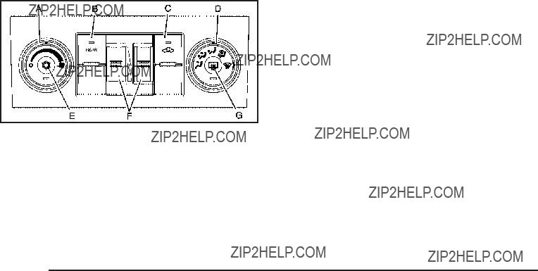
Climate Controls
Climate Control System
The heating, cooling, and ventilation in the vehicle can be controlled with this system.
Temperature Control: Move the thumbwheels up or down to increase or decrease the temperature on
the driver???s side or the passenger side of the vehicle for the dual zone system.
9 (Fan Control): Turn the left knob clockwise or counterclockwise to increase or decrease the fan speed. Turn the knob all the way counterclockwise to turn the front system off.
Air Delivery Mode Control: Turn clockwise or counterclockwise to change the air???ow direction inside the vehicle. By positioning the knob between two modes, a combination of those modes is selected.
Select from the following modes:
H (Vent): Air is directed to the instrument panel outlets.
)
6 (Floor): Air is directed to the ???oor outlets, with some of the air directed to the windshield, side window, and second row ???oor outlets. In this mode, the system automatically selects outside air. Recirculation cannot be selected when in Floor Mode.
- (Defog): The defog mode is used to clear the windows of fog or moisture. Air is directed to the windshield, ???oor outlets, and side window vents. In this mode, the system turns off recirculation and runs
the air conditioning compressor unless the outside temperature is close to freezing. The recirculation mode cannot be selected while in the defog mode.
0 (Defrost): The defrost mode is used to remove fog or frost from the windshield more quickly. Air is directed to the windshield and side window vents, with some directed to the ???oor vents. In this mode, the system automatically forces outside air into the vehicle. The recirculation mode cannot be selected while in the defrost mode. The air conditioning compressor runs automatically in this setting, unless the outside temperature is close to freezing.
Do not drive the vehicle until all the windows are clear.
# (Air Conditioning): Press this button to turn the air conditioning system on or off. An indicator light comes on to show that the air conditioning is on. The air conditioning can be selected in any mode as long as the fan switch is on.
On hot days, open the windows to let hot inside air escape; then close them. This helps to reduce the time it takes for the vehicle to cool down. It also helps the system to operate more efficiently.
The air conditioning system removes moisture from the air, so a small amount of water might drip under the vehicle while idling or after turning off the engine. This is normal.
h (Recirculation): Press this button to turn the recirculation mode on or off. An indicator light comes on to show that recirculation is on.
This mode recirculates and helps to quickly cool the air inside the vehicle. It can be used to help prevent outside air and odors from entering the vehicle.
The recirculation mode cannot be used with ???oor, defrost, or defogging modes. If recirculation is selected while in one of those modes, the indicator ???ashes three times and turns off. The air conditioning compressor will also come on when this mode is activated. While in recirculation mode the windows may fog when the weather is cold and damp. To clear the fog, select either the defog or defrost mode and increase the fan speed. The recirculation mode can also be turned off by turning off the engine.
REAR: Press to turn the rear heating and air conditioning on. See Rear Air Conditioning and Heating System on page
on page

Rear Window Defogger
The rear window defogger uses a warming grid to remove fog from the rear window.
< (Rear Window Defogger): Press this button to turn the rear window defogger on or off. The system automatically turns off several minutes after it has been activated. The defogger can also be turned off by turning off the engine. Do not drive the vehicle until all the windows are clear.
For vehicles with heated outside rearview mirrors, the mirrors will heat to help clear fog or frost from the surface of the mirror when the rear window defog button is pressed.
Notice: Do not use anything sharp on the inside of the rear window. If you do, you could cut or damage the warming grid, and the repairs would not be covered by the vehicle warranty. Do not attach
a temporary vehicle license, tape, a decal or anything similar to the defogger grid.
Dual Automatic Climate Control
System
The heating, cooling, and ventilation in the vehicle can be controlled with this system. The vehicle also has
a
If this vehicle is a

O (On/Off): Press to turn the climate control system on or off. Outside air still enters the vehicle, and is directed to the ???oor. This direction can be changed by pressing the mode button. Recirculation can be selected once you have selected vent or
turned back on by pressing either O , D , C , # , the defrost or the AUTO button.
Driver and Passenger Side Temperature
Control
The driver and passenger side temperature buttons are used to adjust the temperature of the air coming through the system on the driver or passenger???s side of the vehicle. The temperature can be adjusted even if the system is turned off. This is possible since outside air always ???ows through the system as the vehicle
is moving forward unless it is set to recirculation mode. See ???Recirculation??? later in this section.
Press the + or ??? buttons to increase or decrease the cabin temperature. The driver side or passenger
side temperature display shows the temperature setting decreasing or increasing.

The passenger???s temperature setting can be set to match the driver???s temperature setting by pressing the PASS button and turning off the PASS indicator. When the passenger???s temperature setting is set different than the driver???s setting, the indicator on the PASS button illuminates and both the driver side
and passenger side temperature displays are shown.
Automatic Operation
AUTO (Automatic): When automatic operation is active the system will control the inside temperature, the air delivery, and the fan speed.
Use the steps below to place the entire system in automatic mode:
1.Press the AUTO button.
When AUTO is selected, the display will change to show the current temperature(s) and AUTO will
be lit on the display. The current delivery mode and fan speed will also be displayed for approximately 5 seconds.
When AUTO is selected, the air conditioning operation and air inlet will be automatically controlled. The air conditioning compressor will run when the outside temperature is over about
40??F (4??C). The air inlet will normally be set to outside air. If it is hot outside, the air inlet may
automatically switch to recirculate inside air to help quickly cool down the vehicle. The light on the button comes on in recirculation.
2.Set the driver???s and passenger???s temperature.
To ???nd your comfort setting, start with a 74??F (23??C) temperature setting and allow about 20 minutes
for the system to regulate. Use the driver???s or passenger???s temperature buttons to adjust the temperature setting as necessary. If a temperature setting of 60??F (15??C) is chosen, the system remains at the maximum cooling setting. If a temperature setting of 90??F (32??C) is chosen, the system remains at the maximum heat setting. Choosing either maximum setting will not cause the vehicle to heat or cool any faster.
Do not to cover the solar sensor located on the top
of the instrument panel near the windshield. This sensor regulates air temperature based on sun load and also turns on the headlamps. For more information on
the solar sensor, see ???Sensors??? later in this section.
To avoid blowing cold air in cold weather, the system will delay turning on the fan until warm air is available.
The length of delay depends on the engine coolant temperature. Pressing the fan switch will override this delay and change the fan to a selected speed.
Manual Operation
D C (Fan Control): Press these buttons to increase or decrease the fan speed.
Pressing either fan button while in automatic control places the fan under manual control. The fan setting remains displayed and the AUTO light turns off. The air delivery mode remains under automatic control.
H G (Air Delivery Mode Control): Press these buttons to change the direction of the air???ow in the vehicle. Repeatedly press either button until the desired mode appears on the display. Pressing either mode button while the system is off changes the air delivery mode without turning the system on. Pressing either mode button while in automatic control places the mode under manual control.
The air delivery mode setting is displayed and the AUTO light turns off. The fan remains under automatic control.
H (Vent): Air is directed to the instrument panel outlets.
)
6 (Floor): Air is directed to the ???oor outlets, with some to the windshield, side window outlets, and second row ???oor outlets. In this mode, the system automatically selects outside air.
- (Defog): This mode clears the windows of fog or moisture. Air is directed to the windshield, ???oor outlets, and side window vents. In this mode, the system turns off recirculation and runs the air conditioning compressor unless the outside temperature is close to freezing. The recirculation mode cannot be selected while in the defog mode.
0 (Defrost): This mode removes fog or frost from the windshield more quickly. Air is directed to the windshield and side window vents, with some directed to the ???oor vents. In this mode, the system automatically forces outside air into the vehicle and runs the air conditioning compressor unless the outside temperature is close to freezing. The recirculation mode cannot be selected while in the defrost mode.
Do not drive the vehicle until all the windows are clear.

# (Air Conditioning): Press to turn the air conditioning (A/C) compressor on and off. An indicator light comes on to show that the air conditioning is on.
If this button is pressed when the air conditioning compressor is unavailable, the indicator ???ashes three times and then turns off. If the air conditioning is on and the outside temperature drops below a temperature which is too cool for air conditioning to be effective, the air conditioning light turns off to show that the air conditioning mode has been canceled.
On hot days, open the windows long enough to let hot inside air escape. This helps to reduce the time it takes for the vehicle to cool down. It also helps the system to operate more efficiently.
The air conditioning system removes moisture from the air, so a small amount of water might drip under the vehicle while idling or after turning off the engine. This is normal.
@ (Recirculation): Press to turn the recirculation mode on or off. An indicator light comes on to show that the recirculation is on.
This mode recirculates and helps to quickly cool the air inside the vehicle. It can be used to help prevent outside air and odors from entering the vehicle.
The recirculation mode cannot be used with ???oor, defog, or defrost modes. If recirculation is selected with one of those modes, the indicator light ???ashes three times and then turns off. The air conditioning compressor also comes on when this mode is activated. While in recirculation mode the windows may fog when the weather is cold and damp. To clear the fog, select either the defog or defrost mode and increase the fan speed.
The recirculation mode can also be turned off by turning off the ignition.
REAR: For vehicles with the rear heat and air conditioning controls. Press to turn the rear climate control system on or off. See Rear Air Conditioning and Heating System and Electronic Climate Controls on page

Rear Window Defogger
The rear window defogger uses a warming grid to remove fog from the rear window.
< (Rear Window Defogger): Press to turn the rear window defogger on or off. It automatically turns off several minutes after it has been activated. The defogger can also be turned off by turning off the engine. Do not drive the vehicle until all the windows are clear.
Notice: Do not use a razor blade or sharp object to clear the inside rear window. Do not adhere anything to the defogger grid lines in the rear glass. These actions may damage the rear defogger. Repairs would not be covered by your warranty.
Heated Mirrors: For vehicles with heated outside rearview mirrors, the mirrors heat to help clear fog or frost from the surface of the mirror when the rear window defog button is pressed. See Outside Power Mirrors
on page
Sensors
The solar sensor, located in the defrost grille in the middle of the instrument panel, monitors the solar heat. Do not cover the solar sensor or the system will not work properly.

The interior temperature sensors located in the headliner above the driver side seat and if equipped, in the headliner above the second row seats measure the temperature of the air inside the vehicle.
There is also an exterior temperature sensor located behind the front grille. This sensor reads the outside air temperature and helps maintain the temperature
inside the vehicle. Any cover on the front of the vehicle could cause a false reading in the displayed temperature.
The climate control system uses the information from these sensors to maintain your comfort setting by adjusting the outlet temperature, fan speed, and the air delivery mode. The system may also supply cooler
air to the side of the vehicle facing the sun. The recirculation mode will also be used as needed to maintain cool outlet temperatures.
Outlet Adjustment
Use the air outlets located in the center and on the side of the instrument panel to direct the air???ow.
Operation Tips
???Keep the hood and front air inlets free of ice, snow, or any other obstruction (such as leaves). The heater and defroster will work far better, reducing the chance of fogging the inside of the windows.
???When you enter a vehicle in cold weather, press the fan up button to the maximum fan level before driving. This helps clear the intake ducts of snow and moisture, and reduces the chance of fogging the inside of the window.
???Keep the air path under the front seats clear of objects. This helps air to circulate throughout the vehicle.
???Adding outside equipment to the front of the vehicle, such as

Rear Air Conditioning and Heating
System
For vehicles with this system, the rear controls are three knobs located in the headliner. The system can also be controlled with the front controls.
A.Fan Control
B.Temperature Control
C.Air Delivery Mode Control
REAR: Press the REAR button on the front climate control system to turn the rear climate control system on or off. An indicator comes on when the rear system is on. See Climate Control System on page
Dual Automatic Climate Control System on page
the rear fan knob to the 9 position.
Mimic Mode: This mode matches the rear climate control to the front climate control air???ow settings. It comes on when REAR is pressed the ???rst time.
Independent Mode: This mode directs rear seating air???ow according to the settings of the rear controls. It comes on when any rear control is adjusted.
Temperature Control: Turn clockwise or counterclockwise to increase or decrease the air???ow temperature into the passenger area.
Fan Control: Turn clockwise or counterclockwise to increase or decrease the fan speed.
Air Delivery Mode Control: Turn clockwise or counterclockwise to change the direction of the air???ow.
H (Vent): Air is directed through the headliner outlets.
)
are located directly behind the second row seats. The ???ow can be divided between vent and ???oor outlets depending upon where the knob is placed between the settings.
6 (Floor): Air is directed to the ???oor outlets. The rear system ???oor outlets are located directly behind the second row seats.

Rear Air Conditioning and Heating
System and Electronic Climate
Controls
For vehicles with the rear heat and air conditioning controls, they are integrated with the rear seat audio controls located in the center console. The system can be controlled from the front controls as well as the rear controls.
Rear Climate Control with Rear Seat Audio Controls
A.Fan Control
B.Air Delivery Mode Control
C.Temperature Control
REAR: Press the REAR button on the front climate control system to turn the rear climate control system on or off. An indicator comes on when the rear system is on.
The rear climate control system can also be turned off by pressing and holding the C button. To turn the system on from the rear seats, press any rear climate control button, except the C button.
Mimic Mode: This mode matches the rear climate control to the front climate control air???ow settings. It comes on when REAR is pressed the ???rst time.
Independent Mode: This mode directs rear seating air???ow according to the settings of the rear controls.
To turn the system on from the rear, press any rear climate control button, except the C button.
Automatic Operation, If Equipped.
AUTO: Press the air delivery mode button until this setting is selected to control the inside temperature, air delivery, and fan speed. AUTO appears in the display when automatic operation is active.
+/??? (Increase/Decrease Temperature): Press the + or ??? buttons to increase or decrease the cabin temperature. The rear control temperature display will show the temperature setting increasing or decreasing.
The display only indicates climate control functions when the system is in rear independent mode.
Manual Operation
D C (Fan Control): Press these buttons on the rear seat audio control panel to increase or decrease
the air???ow. Pressing the fan up button when the system is off will turn the system on. The air delivery mode
will remain under automatic control.
+/??? (Temperature Control): Press these buttons to adjust the temperature of the air ???owing into the passenger area. Press the + button for warmer air and press the ??? button for cooler air.
N (Air Delivery Mode Control): Press the mode button to change the direction of the air???ow in the vehicle. Repeatedly press the button until the desired mode appears on the display. Multiple presses will cycle through the delivery selections.

Warning Lights, Gages, and
Indicators
Warning lights and gages can signal that something is wrong before it becomes serious enough to cause
an expensive repair or replacement. Paying attention to the warning lights and gages could prevent injury.
Warning lights come on when there may be or is a problem with one of the vehicle???s functions. Some warning lights come on brie???y when the engine is started to indicate they are working.
Gages can indicate when there may be or is a problem with one of the vehicle???s functions. Often gages and warning lights work together to indicate a problem with the vehicle.
When one of the warning lights comes on and stays on while driving, or when one of the gages shows there may be a problem, check the section that explains what to do. Follow this manual???s advice. Waiting to do repairs can be costly and even dangerous.
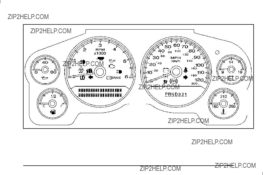
Instrument Panel Cluster
United States
The instrument cluster is designed to show how the vehicle is running. It shows how fast the vehicle is going, about how much fuel the vehicle has and many other things needed to drive safely and economically.
For vehicles with a
Speedometer and Odometer
The speedometer shows the vehicle???s speed in both miles per hour (mph) and kilometers per hour (km/h).
The odometer shows how far the vehicle has been driven, in either miles (used in the United States) or kilometers (used in Canada).
Trip Odometer
The trip odometer can show how far the vehicle has been driven since the trip odometer was last set to zero.
Press the reset button, located on the instrument
panel cluster next to the trip odometer display, to toggle between the trip odometer and the regular odometer. Holding the reset button for approximately one second while the trip odometer is displayed resets it.
To display the odometer reading with the ignition off, press the reset button.
Tachometer
The tachometer displays the engine speed in revolutions per minute (rpm).
Safety Belt Reminders
Safety Belt Reminder Light
When the engine is started, a chime sounds for several seconds to remind a driver to fasten the safety belt, unless the driver safety belt is already buckled.
The safety belt light comes on and stays on for several seconds, then ???ashes for several more.
This chime and light are repeated if the driver remains unbuckled and the vehicle is in motion. If the driver safety belt is already buckled, neither the chime nor the light comes on.
Passenger Safety Belt Reminder Light
Several seconds after the engine is started, a chime sounds for several seconds to remind the front passenger to buckle their safety belt. This only occurs if the passenger airbag is enabled. See Passenger Sensing System on page

This chime and light are repeated if the passenger remains unbuckled and the vehicle is in motion.
If the passenger safety belt is buckled, neither the chime nor the light comes on.
The front passenger safety belt warning light and chime may turn on if an object is put on the seat such as a briefcase, handbag, grocery bag, laptop or other electronic device. To turn off the warning light and or chime, remove the object from the seat or buckle
the safety belt.
Airbag Readiness Light
The system checks the airbag???s electrical system for possible malfunctions. If the light stays on it indicates there is an electrical problem. The system check includes the airbag sensor, the pretensioners, the airbag modules, the wiring and the crash sensing and diagnostic module. For more information on the airbag system, see Airbag System on page
The airbag readiness light ???ashes for a few seconds when the engine is started. If the light does not come on then, have it ???xed immediately.
{ CAUTION:
If the airbag readiness light stays on after the vehicle is started or comes on while driving, it means the airbag system might not be working properly. The airbags in the vehicle might not in???ate in a crash, or they could even in???ate without a crash. To help avoid injury, have the vehicle serviced right away.
If there is a problem with the airbag system, an airbag Driver Information Center (DIC) message can also come on. See DIC Warnings and Messages on page
for more information.

Passenger Airbag Status Indicator
The vehicle has the passenger sensing system. See
Passenger Sensing System on page
When the vehicle is started, the passenger airbag status indicator will light ON and OFF, or the symbol for on and off, for several seconds as a system check. If you are using remote start to start the vehicle from a distance, if equipped, you may not see the system check.
Then, after several more seconds, the status indicator will light either ON or OFF, or either the on or off symbol to let you know the status of the right front passenger frontal airbag.
If the word ON or the on symbol is lit on the passenger airbag status indicator, it means that the right front passenger frontal airbag is enabled (may in???ate).
If the word OFF or the off symbol is lit on the airbag status indicator, it means that the passenger sensing system has turned off the right front passenger frontal airbag.
If, after several seconds, both status indicator lights remain on, or if there are no lights at all, there may be a problem with the lights or the passenger sensing system. See your dealer/retailer for service.
{ CAUTION:
If the airbag readiness light ever comes on and stays on, it means that something may be wrong with the airbag system. To help avoid injury to yourself or others, have the vehicle serviced right away. See Airbag Readiness Light on page
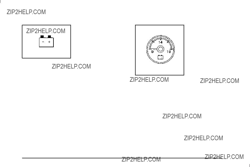
Charging System Light
This light comes on brie???y when the ignition key is turned to START, but
the engine is not running, as a check to show it
is working.
If it does not, have the vehicle serviced by your dealer/retailer.
The light should go out once the engine starts. If it stays on, or comes on while driving, there could be a problem with the charging system. A charging system message in the Driver Information Center (DIC) can also appear. See
DIC Warnings and Messages on page
Voltmeter Gage
When the engine is not running, but the ignition is on, this gage shows
the battery???s state of charge in DC volts.
When the engine is running, the gage shows the condition of the charging system. The charging system regulates voltage based on the state of the battery
for improved fuel economy and battery life. The gage may transition from a higher to lower or a lower to higher reading, this is normal. Readings between the low
and high warning zones indicate the normal operating range. The gage may also read low during the fuel economy mode, this is normal.

Readings in the low warning zone may occur when a large number of electrical accessories are operating in the vehicle and the engine is left at an idle for an extended period. This condition is normal since the charging system is not able to provide full power at engine idle. As engine speeds are increased, this condition should correct itself as higher engine speeds allow the charging system to create full power. If there is a problem with the battery charging system, this light will come on or the SERVICE BATTERY CHARGING SYSTEM DIC message will display. See DIC Warnings and Messages on page
Brake System Warning Light
With the ignition on, the brake system warning light comes on when the parking brake is set. If the vehicle is driven with the parking brake engaged, a chime sounds when the vehicle speed is greater than
5 mph (8 km/h).
The vehicle???s hydraulic brake system is divided into two parts. If one part is not working, the other part can
still work and stop the vehicle. For good braking, both parts need to be working well.
If the warning light comes on and a chime sounds there could be a brake problem. Have the brake system inspected right away.
This light can also come on due to low brake ???uid. See Brakes on page
This light comes on brie???y when the ignition key is turned to ON/RUN. If it does not come on then, have it ???xed so it is ready to warn if there is a problem.

{ CAUTION:
The brake system might not be working properly if the brake system warning light is on. Driving with the brake system warning light on can lead to a crash. If the light is still on after the vehicle has been pulled off the road and carefully stopped, have the vehicle towed for service.
If the light comes on while driving, pull off the road and stop carefully. The pedal might be harder to push or might go closer to the ???oor. It can take longer to stop. If the light is still on, have the vehicle towed for service. See Towing Your Vehicle on page
Antilock Brake System (ABS)
Warning Light
For vehicles with the Antilock Brake System (ABS), this light comes on brie???y when the engine is started.
If it does not, have the vehicle serviced by your dealer/ retailer. If the system is working normally the indicator light then goes off.
If the ABS light stays on, turn the ignition off. If the light comes on while driving, stop as soon as it is safely possible and turn the ignition off. Then start the engine again to reset the system. If the ABS light stays on, or comes on again while driving, the vehicle needs service. If the regular brake system warning light is not on, the vehicle still has brakes, but not antilock brakes. If the regular brake system warning light is also on, the vehicle does not have antilock brakes and there is a problem with the regular brakes. See Brake System Warning Light on page
For vehicles with a Driver Information Center (DIC), see
DIC Warnings and Messages on page
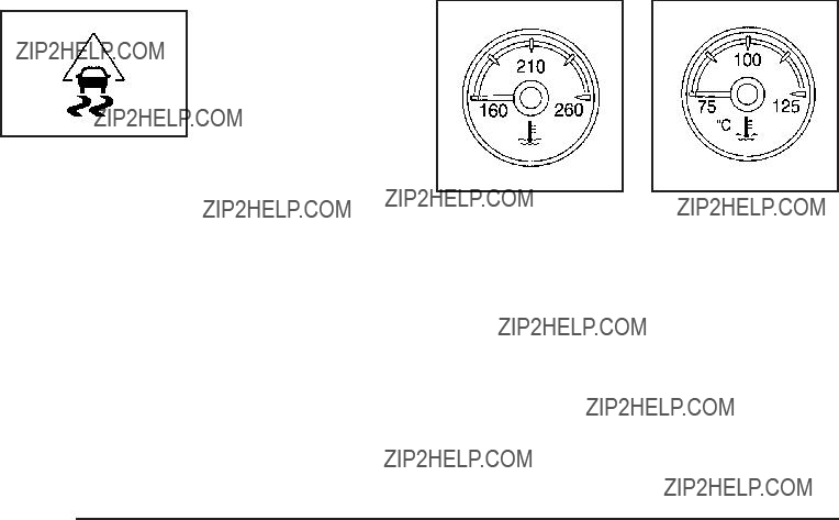
For vehicles with the StabiliTrak?? system, this light comes on brie???y while starting the engine.
If it does not, have the vehicle serviced by your dealer/retailer. If the system is working normally the indicator light then goes off.
If the light comes on and stays on while driving, there could be a problem with the StabiliTrak?? system and the vehicle might need service. When this warning light is on, the StabiliTrak?? system is off and does not limit wheel spin.
The light ???ashes if the system is active and is working to assist the driver with directional control of the vehicle in difficult driving conditions.
See StabiliTrak?? System on page
This gage shows the engine coolant temperature.
It also provides an indicator of how hard the vehicle is working. During a majority of the operation, the gage reads 210??F (100??C) or less. If you are pulling a load or going up hills, it is normal for the temperature to ???uctuate and approach the 250??F (122??C) mark. If the gage reaches the 260??F (125??C) mark, it indicates that the cooling system is working beyond its capacity.
See Engine Overheating on page
If the vehicle is a
Tire Pressure Light
For vehicles with a tire pressure monitoring system, this light comes on brie???y when the engine is started.
It provides information about tire pressures and the Tire Pressure Monitoring System.
When the Light is On Steady
This indicates that one or more of the tires is signi???cantly underin???ated.
A tire pressure message in the Driver Information Center (DIC), can accompany the light. See DIC Warnings and Messages on page
When the Light Flashes First and Then is On Steady
This indicates that there could be a problem with the Tire Pressure Monitor System. The light ???ashes for about a minute and stays on steady for the remainder of the ignition cycle. This sequence repeats with every ignition cycle. See Tire Pressure Monitor System on page
Malfunction Indicator Lamp
Check Engine Light
A computer system called OBD II

This light should come on when the ignition is on, but the engine is not running, as a check to show it
is working. If it does not, have the vehicle serviced by your dealer/retailer.
If the check engine light comes on and stays on, while the engine is running, this indicates that there is an OBD II problem and service is required.
Malfunctions often are indicated by the system before any problem is apparent. Being aware of the light can prevent more serious damage to the vehicle. This system assists the service technician in correctly diagnosing any malfunction.
Notice: If the vehicle is continually driven with this light on, after a while, the emission controls might not work as well, the vehicle???s fuel economy might not be as good, and the engine might not run as smoothly. This could lead to costly repairs that might not be covered by the vehicle warranty.
Notice: Modi???cations made to the engine, transmission, exhaust, intake, or fuel system of the vehicle or the replacement of the original tires with other than those of the same Tire Performance Criteria (TPC) can affect the vehicle???s emission controls and can cause this light to come on. Modi???cations to these systems could lead to costly repairs not covered by the vehicle warranty. This could also result in a failure to pass a required Emission Inspection/Maintenance test. See
Accessories and Modi???cations on page
This light comes on during a malfunction in one of two ways:
Light Flashing: A mis???re condition has been detected. A mis???re increases vehicle emissions and could damage the emission control system on the vehicle. Diagnosis and service might be required.
To prevent more serious damage to the vehicle:
???Reduce vehicle speed.
???Avoid hard accelerations.
???Avoid steep uphill grades.
???If towing a trailer, reduce the amount of cargo being hauled as soon as it is possible.

If the light continues to ???ash, when it is safe to do so, stop the vehicle. Find a safe place to park the vehicle. Turn the key off, wait at least 10 seconds, and restart the engine. If the light is still ???ashing, follow the previous steps and see your dealer/retailer for service as soon as possible.
Light On Steady: An emission control system malfunction has been detected on the vehicle. Diagnosis and service might be required.
An emission system malfunction might be corrected by doing the following:
???Make sure the fuel cap is fully installed. See Filling the Tank on page
???If the vehicle has been driven through a deep puddle of water, the vehicle???s electrical system might be wet. The condition is usually corrected when the electrical system dries out. A few driving trips should turn the light off.
???Make sure to fuel the vehicle with quality fuel. Poor fuel quality causes the engine not to run as efficiently as designed and can cause: stalling after
into gear, mis???ring, hesitation on acceleration, or stumbling on acceleration. These conditions might go away once the engine is warmed up.
If one or more of these conditions occurs, change the fuel brand used. It will require at least one full tank of the proper fuel to turn the light off.
See Gasoline Octane on page
If none of the above have made the light turn off, your dealer/retailer can check the vehicle. The dealer/retailer has the proper test equipment and diagnostic tools to ???x any mechanical or electrical problems that might have developed.
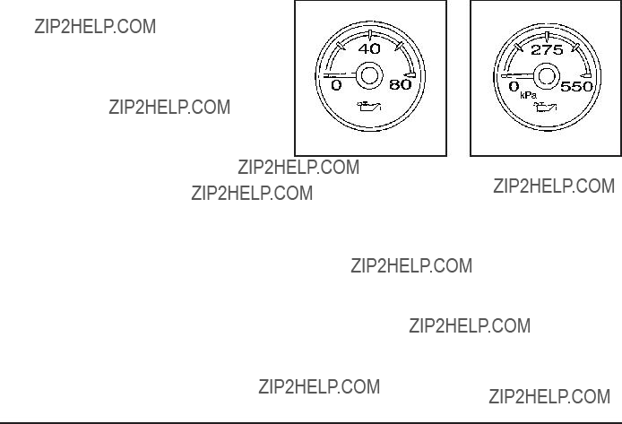
Emissions Inspection and Maintenance
Programs
Some state/provincial and local governments have or might begin programs to inspect the emission control equipment on the vehicle. Failure to pass this inspection could prevent getting a vehicle registration.
Here are some things to know to help the vehicle pass an inspection:
???The vehicle will not pass this inspection if the check engine light is on with the engine running, or if the key is in ON/RUN and the light is not on.
???The vehicle will not pass this inspection if the OBD II
Oil Pressure Gage
The oil pressure gage shows the engine oil pressure in psi (pounds per square inch) when the engine is running. Canadian vehicles indicate pressure in
kPa (kilopascals).

Oil pressure may vary with engine speed, outside temperature and oil viscosity, but readings above the low pressure zone indicate the normal operating range. When the oil pressure reaches the low pressure
zone, the OIL PRESSURE LOW STOP ENGINE message appears in the Driver Information Center (DIC). See DIC Warnings and Messages on page
A reading in the low pressure zone may be caused by a dangerously low oil level or some other problem causing low oil pressure. Check the oil as soon as possible.
{ CAUTION:
Do not keep driving if the oil pressure is low. The engine can become so hot that it catches ???re. Someone could be burned. Check the oil as soon as possible and have the vehicle serviced.
Notice: Lack of proper engine oil maintenance can damage the engine. The repairs would not be covered by the vehicle warranty. Always follow the maintenance schedule in this manual for changing engine oil.
If the vehicle is a

Oil Pressure Light
{ CAUTION:
Do not keep driving if the oil pressure is low. The engine can become so hot that it catches ???re. Someone could be burned. Check the oil as soon as possible and have the vehicle serviced.
Notice: Lack of proper engine oil maintenance can damage the engine. The repairs would not be covered by the vehicle warranty. Always follow the maintenance schedule in this manual for changing engine oil.
This light comes on brie???y while starting the engine. If it does not, have the vehicle serviced by your dealer/ retailer. If the system is working normally the indicator light then goes off.
If the light comes on and stays on, it means that oil is not ???owing through the engine properly. The vehicle could be low on oil and it might have some other system problem.
Security Light
For information regarding this light and the vehicle???s security system, see
Content
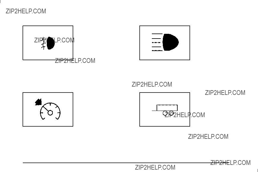
The fog lamp light comes on when the fog lamps are in use.
The light goes out when the fog lamps are turned off. See Fog Lamps on page
Cruise Control Light
This light comes on when the
See Headlamp
Tow/Haul Mode Light
The cruise control light comes on whenever the cruise control is set.
The light goes out when the cruise control is turned off. See Cruise Control on page
This light comes on when the Tow/Haul mode has been activated.
For more information, see Tow/Haul Mode on page
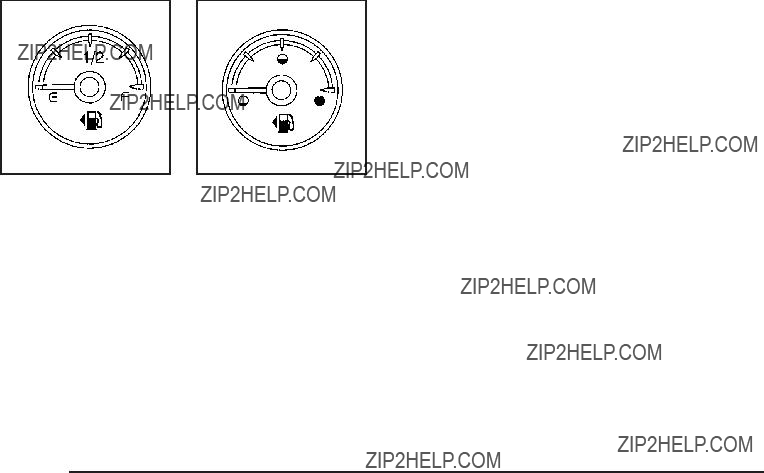
Fuel Gage
The fuel gage, when the ignition is on, shows how much fuel the vehicle has left in the tank.
An arrow on the fuel gage indicates the side of the vehicle the fuel door is on.
The gage ???rst indicates empty before the vehicle is out of fuel, and the vehicle???s fuel tank should be ???lled soon.
When the fuel tank is low, the FUEL LEVEL LOW message appears in the Driver Information Center (DIC). See DIC Warnings and Messages on page
Here are some situations owners may experience with the fuel gage. None of these indicate a problem
with the fuel gage.
???At the gas station, the fuel pump shuts off before the gage reads full.
???It takes a little more or less fuel to ???ll up than the fuel gage indicated. For example, the gage may have indicated the tank was half full, but it actually took a little more or less than half the tank???s capacity to ???ll the tank.
???The gage goes back to empty when the ignition is turned off.
For vehicles with a

Low Fuel Warning Light
This light, under the fuel gage, comes on brie???y while the engine is being started.
This light and a chime comes on when the fuel tank is low on fuel. The Driver Information Center also displays a ???FUEL LEVEL LOW??? message. See DIC Warnings and Messages on page
it does not, have the vehicle serviced by your dealer/retailer.
Driver Information Center (DIC)
Your vehicle has a Driver Information Center (DIC).
The DIC displays information about your vehicle. It also displays warning messages if a system problem is detected.
All messages will appear in the DIC display located below the tachometer in the instrument panel cluster.
The DIC comes on when the ignition is on. After a short delay, the DIC will display the information that was
last displayed before the engine was turned off.
If your vehicle has DIC buttons, see ???DIC Operation and Displays (With DIC Buttons)??? later in this section and
DIC Vehicle Customization (With DIC Buttons) on page
If your vehicle does not have DIC buttons, see ???DIC Operation and Displays (Without DIC Buttons)??? later in this section for the displays available.

DIC Operation and Displays (With
DIC Buttons)
If your vehicle has DIC buttons, the information below explains the operation of this system.
The DIC has different displays which can be accessed by pressing the DIC buttons located on the instrument panel, next to the steering wheel.
The DIC displays trip, fuel, and vehicle system information, and warning messages if a system problem is detected.
The DIC also allows some features to be customized. See DIC Vehicle Customization (With DIC Buttons) on page
If your vehicle has DIC buttons, you can also use the trip odometer reset stem to view some of the DIC displays. See ???DIC Operation and Displays (Without DIC Buttons)??? later in this section.
DIC Buttons
The buttons are the trip/fuel, vehicle information, customization, and set/reset buttons. The button functions are detailed in the following pages.
3 (Trip/Fuel): Press this button to display the odometer, trip odometer, fuel range, average economy, fuel used, timer, and transmission temperature. The compass and outside air temperature will also be shown in the display. The temperature will be shown in ??F or ??C depending on the units selected.
T (Vehicle Information): Press this button to display the oil life, units, side blind zone system on/off, tire pressure readings for vehicles with the Tire Pressure Monitor System (TPMS), trailer brake gain and output information for vehicles with the Integrated Trailer Brake Control (ITBC) system, engine hours, Remote Keyless Entry (RKE) transmitter programming, compass zone setting, and compass recalibration.
U (Customization): Press this button to customize the feature settings on your vehicle. See DIC Vehicle Customization (With DIC Buttons) on page
V (Set/Reset): Press this button to set or reset certain functions and to turn off or acknowledge messages
on the DIC.
Trip/Fuel Menu Items
3 (Trip/Fuel): Press this button to scroll through the following menu items:
Odometer
Press the trip/fuel button until ODOMETER displays. This display shows the distance the vehicle has been driven in either miles (mi) or kilometers (km). Pressing the trip odometer reset stem will also display the odometer.
To switch between English and metric measurements, see ???Units??? later in this section.
Trip Odometer
Press the trip/fuel button until TRIP displays. This display shows the current distance traveled in either miles (mi) or kilometers (km) since the last reset for the trip odometer. Pressing the trip odometer reset stem will also display the trip odometer.
The trip odometer can be reset to zero by pressing the set/reset button while the trip odometer is displayed. You can also reset the trip odometer while it is displayed by pressing and holding the trip odometer reset stem.
The trip odometer has a feature called the
To use the

Once the vehicle begins moving, the trip odometer will accumulate mileage. For example, if the vehicle was driven 5 miles (8 km) before it is started again, and then the
Fuel Range
Press the trip/fuel button until FUEL RANGE displays. This display shows the approximate number of remaining miles (mi) or kilometers (km) the vehicle can be driven without refueling. The display will show LOW if the fuel level is low.
The fuel range estimate is based on an average of the vehicle???s fuel economy over recent driving history
and the amount of fuel remaining in the fuel tank. This estimate will change if driving conditions change.
For example, if driving in traffic and making frequent stops, this display may read one number, but if
the vehicle is driven on a freeway, the number may change even though the same amount of fuel is in the fuel tank. This is because different driving conditions produce different fuel economies. Generally, freeway driving produces better fuel economy than city driving. Fuel range cannot be reset.
Average Economy
Press the trip/fuel button until AVG ECONOMY displays. This display shows the approximate average miles
per gallon (mpg) or liters per 100 kilometers (L/100 km). This number is calculated based on the number of mpg (L/100 km) recorded since the last time this menu item was reset. To reset AVG ECONOMY, press
and hold the set/reset button.
Fuel Used
Press the trip/fuel button until FUEL USED displays. This display shows the number of gallons (gal) or liters (L) of fuel used since the last reset of this menu item. To reset the fuel used information, press and hold the set/reset button while FUEL USED is displayed.
Timer
Press the trip/fuel button until TIMER displays. This display can be used as a timer.
To start the timer, press the set/reset button while TIMER is displayed. The display will show the amount of time that has passed since the timer was last reset, not including time the ignition is off. Time will continue to be counted as long as the ignition is on, even if another display is being shown on the DIC. The timer will record up to 99 hours, 59 minutes and 59 seconds (99:59:59) after which the display will return to zero.

To stop the timer, press the set/reset button brie???y while TIMER is displayed.
To reset the timer to zero, press and hold the set/reset button while TIMER is displayed.
Transmission Temperature
Press the trip/fuel button until TRANS TEMP displays. This display shows the temperature of the automatic transmission ???uid in either degrees Fahrenheit (??F) or degrees Celsius (??C).
Blank Display
This display shows no information.
Vehicle Information Menu Items
T (Vehicle Information): Press this button to scroll through the following menu items:
Oil Life
Press the vehicle information button until OIL LIFE REMAINING displays. This display shows an estimate of the oil???s remaining useful life. If you see 99% OIL LIFE REMAINING on the display, that means 99% of the current oil life remains. The engine oil life system
will alert you to change the oil on a schedule consistent with your driving conditions.
When the remaining oil life is low, the CHANGE ENGINE OIL SOON message will appear on the display. See ???CHANGE ENGINE OIL SOON??? under DIC Warnings and Messages on page
Remember, you must reset the OIL LIFE display yourself after each oil change. It will not reset itself. Also, be careful not to reset the OIL LIFE display accidentally at any time other than when the oil has just been changed. It cannot be reset accurately until the next oil change. To reset the engine oil life system, see
Engine Oil Life System on page

Side Blind Zone Alert
If your vehicle has the Side Blind Zone Alert (SBZA) system, this display allows the system to be turned on or off. Once in this display, press the set/reset button to select between ON or OFF. If you choose ON, the system will be turned on. If you choose OFF, the system will be turned off. When the SBZA system is turned
off, the DIC will display the SIDE BLIND ZONE ALERT SYSTEM OFF message as a reminder that the system has been turned off. See DIC Warnings and Messages on page
Units
Press the vehicle information button until UNITS displays. This display allows you to select between English or Metric units of measurement. Once in this display, press the set/reset button to select between ENGLISH or METRIC units. All of the vehicle information will then be displayed in the unit of measurement selected.
Tire Pressure
On vehicles with the Tire Pressure Monitor System (TPMS), the pressure for each tire can be viewed in the DIC. The tire pressure will be shown in either pounds per square inch (psi) or kilopascals (kPa). Press
the vehicle information button until the DIC displays FRONT TIRES PSI (kPa) LEFT ## RIGHT ##. Press the vehicle information button again until the DIC displays REAR TIRES PSI (kPa) LEFT ## RIGHT ##.
If a low or high tire pressure condition is detected by the system while driving, a message advising you to
check the pressure in a speci???c tire will appear in the display. See In???ation - Tire Pressure on page
If the tire pressure display shows dashes instead of a value, there may be a problem with your vehicle. If this consistently occurs, see your dealer/retailer for service.

Trailer Gain and Output
On vehicles with the Integrated Trailer Brake Control (ITBC) system, the trailer brake display appears in the DIC. Press the vehicle information button until TRAILER GAIN and OUTPUT display.
TRAILER GAIN shows the trailer gain setting. This setting can be adjusted from 0.0 to 10.0 with either a trailer connected or disconnected. To adjust this setting, see ???Integrated Trailer Brake Control System??? under
Towing a Trailer on page
OUTPUT shows the power output to the trailer anytime a trailer with electric brakes is connected. Output is displayed in 0 to 10 bars. Dashes may appear in
the OUTPUT display. See ???Integrated Trailer Brake Control System??? under Towing a Trailer on page
Engine Hours
Press the vehicle information button until ENGINE HOURS displays. This display shows the total number of hours the engine has run.
Relearn Remote Key
This display allows you to match Remote Keyless Entry (RKE) transmitters to your vehicle. To match an RKE transmitter to your vehicle:
1.Press the vehicle information button until
PRESS V TO RELEARN REMOTE KEY displays.
2.Press the set/reset button until REMOTE KEY LEARNING ACTIVE is displayed.
3.Press and hold the lock and unlock buttons on the ???rst transmitter at the same time for about
15 seconds.
On vehicles with memory recall seats, the ???rst transmitter learned will match driver 1 and the second will match driver 2.
A chime will sound indicating that the transmitter is matched.
4.To match additional transmitters at this time, repeat Step 3.
Each vehicle can have a maximum of eight transmitters matched to it.
5.To exit the programming mode, you must cycle the key to LOCK/OFF.

Compass Zone Setting
This display allows for setting the compass zone. See
DIC Compass on page
Compass Recalibration
This display allows for calibrating the compass. See DIC Compass on page
Blank Display
This display shows no information.
DIC Operation and Displays
(Without DIC Buttons)
If your vehicle does not have DIC buttons, the information below explains the operation of this system.
The DIC has different displays which can be accessed by pressing the trip odometer reset stem located on the instrument panel cluster. Pressing the trip odometer reset stem will also turn off, or acknowledge, DIC messages.
The DIC displays trip and vehicle system information, and warning messages if a system problem is detected.
If your vehicle does not have DIC buttons, you can use the trip odometer reset stem to view the following displays: odometer, engine hours, trip odometer, compass zone setting, compass recalibration, oil life, Remote Keyless Entry (RKE) transmitter programming, and display language.
If your vehicle has DIC buttons, you can use the trip odometer reset stem to view the following displays: odometer, engine hours, trip odometer, and display language.
Trip Odometer Reset Stem Menu Items
Odometer
Press the trip odometer reset stem until ODOMETER displays. This display shows the distance the vehicle has been driven in either miles (mi) or kilometers (km).
Engine Hours
To display the ENGINE HOURS, place the ignition in LOCK/OFF or ACC/ACCESSORY, then press and hold the trip odometer reset stem for four seconds while viewing the ODOMETER. This display shows the total number of hours the engine has run.
Trip Odometer
Press the trip odometer reset stem until TRIP displays. This display shows the current distance traveled in either miles (mi) or kilometers (km) since the last reset for the trip odometer.
The trip odometer can be reset to zero by pressing and holding the trip odometer reset stem while the trip odometer is displayed.
The trip odometer has a feature called the
To use the
Transmission Temperature
Press the trip odometer reset stem until TRANS TEMP displays. This display shows the temperature of the automatic transmission ???uid in either degrees Fahrenheit (??F) or degrees Celsius (??C).
Trailer Gain and Output
On vehicles with the Integrated Trailer Brake Control (ITBC) system, the trailer brake display appears in the DIC. Press the trip odometer reset stem until TRAILER GAIN and OUTPUT display.
TRAILER GAIN shows the trailer gain setting. This setting can be adjusted from 0.0 to 10.0 with either a trailer connected or disconnected. To adjust this setting, see ???Integrated Trailer Brake Control System??? under
Towing a Trailer on page
OUTPUT shows the power output to the trailer anytime a trailer with electric brakes is connected. Output is displayed in 0 to 10 bars. Dashes may appear in
the OUTPUT display. See ???Integrated Trailer Brake Control System??? under Towing a Trailer on page

Compass Zone Setting
This display allows for setting the compass zone. See
DIC Compass on page
Compass Recalibration
This display allows for calibrating the compass. See DIC Compass on page
Oil Life
To access this display, the vehicle must be in P (Park). Press the trip odometer reset stem until OIL LIFE REMAINING displays. This display shows an estimate of the oil???s remaining useful life. If you see 99% OIL LIFE REMAINING on the display, that means 99% of the current oil life remains. The engine oil life system
will alert you to change the oil on a schedule consistent with your driving conditions.
When the remaining oil life is low, the CHANGE ENGINE OIL SOON message will appear on the display. See ???CHANGE ENGINE OIL SOON??? under DIC Warnings and Messages on page
Remember, you must reset the OIL LIFE display yourself after each oil change. It will not reset itself. Also, be careful not to reset the OIL LIFE display accidentally at any time other than when the oil has just been changed. It cannot be reset accurately until the next oil change. To reset the engine oil life system, see
Engine Oil Life System on page
Relearn Remote Key
To access this display, the vehicle must be in P (Park). This display allows you to match Remote Keyless Entry (RKE) transmitters to your vehicle. To match an RKE transmitter to your vehicle:
1.Press the trip odometer reset stem until RELEARN REMOTE KEY displays.
2.Press and hold the trip odometer reset stem for three seconds.
The message REMOTE KEY LEARNING ACTIVE will display.
3.Press and hold the lock and unlock buttons on the ???rst transmitter at the same time for about
15 seconds.
On vehicles with memory recall seats, the ???rst transmitter learned will match driver 1 and the second will match driver 2.
A chime will sound indicating that the transmitter is matched.
4.To match additional transmitters at this time, repeat Step 3.
Each vehicle can have a maximum of eight transmitters matched to it.
5.To exit the programming mode, you must cycle the key to LOCK/OFF.
Language
This display allows you to select the language in which the DIC messages will appear. To select a language:
1.Press the trip odometer reset stem until ODOMETER displays.
2.While in the ODOMETER display, press and hold the trip odometer reset stem for three seconds until the currently set language displays.
3.Continue to press and hold the trip odometer reset stem to scroll through all of the available languages.
The available languages are ENGLISH (default), FRANCAIS (French), ESPANOL (Spanish), and
NO CHANGE.
4.Once the desired language is displayed, release the trip odometer reset stem to set your choice.
DIC Compass
Your vehicle may have a compass in the Driver Information Center (DIC).
Compass Zone
The zone is set to zone eight upon leaving the factory. Your dealer/retailer will set the correct zone for your location.
Under certain circumstances, such as during a long distance
Compass variance is the difference between the earth???s magnetic north and true geographic north. If the compass is not set to the zone where you live, the compass may give false readings. The compass must be set to the variance zone in which the vehicle is traveling.

To adjust for compass variance, use the following procedure:
Compass Variance (Zone) Procedure
1.Do not set the compass zone when the vehicle is moving. Only set it when the vehicle is in P (Park).
Press the vehicle information button until PRESS
V TO CHANGE COMPASS ZONE displays.
Or, if the vehicle does not have DIC buttons, press the trip odometer reset stem until CHANGE COMPASS ZONE displays.
2. Find the vehicle???s current location and variance zone number on the map.
Zones 1 through 15 are available.
3. Press the set/reset button to scroll through and select the appropriate variance zone.
4.Press the trip/fuel button until the vehicle heading, for example, N for North, is displayed in the DIC. Or, if the vehicle does not have
DIC buttons, press and hold the trip odometer reset stem for two seconds to select the next available variance zone. Repeat this step until the appropriate variance zone is displayed.
5.If calibration is necessary, calibrate the compass. See ???Compass Calibration Procedure??? following.
Compass Calibration
The compass can be manually calibrated. Only calibrate the compass in a magnetically clean and safe location, such as an open parking lot, where driving the vehicle in circles is not a danger. It is suggested to calibrate away from tall buildings, utility wires, manhole covers, or other industrial structures, if possible.
If CAL should ever appear in the DIC display, the compass should be calibrated.
If the DIC display does not show a heading, for example, N for North, or the heading does not change after making turns, there may be a strong magnetic ???eld interfering with the compass. Such interference may be caused by a magnetic CB or cell phone antenna mount, a magnetic emergency light, magnetic note pad holder, or any other magnetic item. Turn off the vehicle, move the magnetic item, then turn on the vehicle and calibrate the compass.
To calibrate the compass, use the following procedure:
Compass Calibration Procedure
1.Before calibrating the compass, make sure the compass zone is set to the variance zone in which the vehicle is located. See ???Compass Variance (Zone) Procedure??? earlier in this section.
Do not operate any switches such as window, sunroof, climate controls, seats, etc. during the calibration procedure.
2.Press the vehicle information button until PRESS V TO CALIBRATE COMPAS (Compass) displays. Or, if the vehicle does not have DIC buttons, press the trip odometer reset stem until CALIBRATE COMPASS displays.
3.Press the set/reset button to start the compass calibration. Or, if the vehicle does not have DIC buttons, press and hold the trip odometer reset stem for two seconds to start the compass calibration.
4.The DIC will display CALIBRATING: DRIVE IN CIRCLES. Drive the vehicle in tight circles at less than 5 mph (8 km/h) to complete the calibration. The DIC will display CALIBRATION COMPLETE for a few seconds when the calibration is complete. The DIC display will then return to the previous menu.

DIC Warnings and Messages
Messages are displayed on the DIC to notify the driver that the status of the vehicle has changed and that some action may be needed by the driver to correct the condition. Multiple messages may appear one after another.
Some messages may not require immediate action, but you can press any of the DIC buttons on the instrument panel or the trip odometer reset stem on the instrument panel cluster to acknowledge that you received the messages and to clear them from the display.
Some messages cannot be cleared from the DIC display because they are more urgent. These messages require action before they can be cleared. You should take any messages that appear on the display seriously and remember that clearing the messages will only make the messages disappear, not correct the problem.
The following are the possible messages that can be displayed and some information about them.
If your vehicle is a
CHANGE ENGINE OIL SOON
This message displays when the engine oil needs to be changed. When you change the engine oil, be sure to reset the CHANGE ENGINE OIL SOON message. See
Engine Oil Life System on page
CHECK TIRE PRESSURE
On vehicles with the Tire Pressure Monitor System (TPMS), this message displays when the pressure in one or more of the vehicle???s tires needs to be checked. This message also displays LEFT FRONT, RIGHT FRONT, LEFT REAR, or RIGHT REAR to indicate which tire needs to be checked. You can receive more than one tire pressure message at a time. To read the other messages that may have been sent at the same
time, press the set/reset button or the trip odometer reset stem. If a tire pressure message appears on the DIC, stop as soon as you can. Have the tire pressures checked and set to those shown on the Tire Loading Information label. See Tires on page
on page
DIC Buttons)??? earlier in this section. If the tire pressure is low, the low tire pressure warning light comes on. See Tire Pressure Light on page

CHECK TRAILER WIRING
On vehicles with the Integrated Trailer Brake Control (ITBC) system, this message may display and a chime may sound when one of the following conditions exists:
???A trailer with electric brakes becomes disconnected from the vehicle.
???If the disconnect occurs while the vehicle is stopped, this message clears itself after a short time.
???If the disconnect occurs while the vehicle is moving, this message stays on until the ignition is turned off.
???There is a short in the wiring to the electric trailer brakes.
When this message displays, power is no longer available to the trailer brakes.
As soon as it is safe to do so, carefully pull your vehicle over to the side of the road and turn the ignition off. Check the wiring connection to the trailer and turn the ignition back on. This message clears if the trailer is reconnected. This message also clears if you acknowledge it. If this message still displays, either your vehicle or the trailer needs service. See your dealer/retailer.
See ???Integrated Trailer Brake Control System??? under
Towing a Trailer on page
DRIVER DOOR OPEN
This message displays and a chime sounds if the driver door is not fully closed and the vehicle is shifted out
of P (Park). Stop and turn off the vehicle, check the door for obstructions, and close the door again. Check to see if the message still appears on the DIC.
ENGINE HOT A/C (Air Conditioning)
TURNED OFF
This message displays when the engine coolant becomes hotter than the normal operating temperature. See Engine Coolant Temperature Gage on page
If this message continues to appear, have the system repaired by your dealer/retailer as soon as possible to avoid damage to the engine.
ENGINE OIL HOT IDLE ENGINE
This message displays when the engine oil becomes hotter than the normal operating temperature. Stop and allow the vehicle to idle until it cools down. See
Engine Coolant Temperature Gage on page

ENGINE OVERHEATED IDLE ENGINE
Notice: If you drive your vehicle while the engine is overheating, severe engine damage may occur. If an overheat warning appears on the instrument panel cluster and/or DIC, stop the vehicle as soon as possible. See Engine Overheating on page
This message displays when the engine coolant temperature is too hot. Stop and allow the vehicle to idle until it cools down. See Engine Coolant Temperature Gage on page
See Overheated Engine Protection Operating Mode on page
in an emergency.
ENGINE OVERHEATED STOP ENGINE
Notice: If you drive your vehicle while the engine is overheating, severe engine damage may occur. If an overheat warning appears on the instrument panel cluster and/or DIC, stop the vehicle as soon as possible. See Engine Overheating on page
This message displays and a chime sounds if the engine cooling system reaches unsafe temperatures for operation. Stop and turn off the vehicle as soon as it is safe to do so to avoid severe damage. This message clears when the engine has cooled to a safe operating temperature.
ENGINE POWER IS REDUCED
This message displays and a chime sounds when the cooling system temperature gets too hot and the engine further enters the engine coolant protection mode.
See Engine Overheating on page
This message also displays when the vehicle???s engine power is reduced. Reduced engine power can affect the vehicle???s ability to accelerate. If this message is on,
but there is no reduction in performance, proceed
to your destination. The performance may be reduced the next time the vehicle is driven. The vehicle may
be driven at a reduced speed while this message is on, but acceleration and speed may be reduced. Anytime this message stays on, the vehicle should be taken
to your dealer/retailer for service as soon as possible.
FUEL LEVEL LOW
This message displays and a chime sounds if the fuel level is low. Refuel as soon as possible. See Fuel Gage on page
HEATED WASHER FLUID SYSTEM OFF
This message displays when the heated windshield washer has been turned off. See Windshield Washer on page
HEATING WASH FLUID WASH WIPES
PENDING
This message displays when the heated windshield washer system is heating the ???uid. See Windshield Washer on page
HOOD OPEN
This message displays and a chime sounds if the hood is not fully closed. Stop and turn off the vehicle, check the hood for obstructions, and close the hood again. Check to see if the message still appears on the DIC.
ICE POSSIBLE DRIVE WITH CARE
This message displays when ice conditions are possible.
LEFT REAR DOOR OPEN
This message displays and a chime sounds if the driver side rear door is not fully closed and the vehicle is shifted out of P (Park). Stop and turn off the vehicle, check the door for obstructions, and close the door again. Check to see if the message still appears on the DIC.
OIL PRESSURE LOW STOP ENGINE
Notice: If you drive your vehicle while the engine oil pressure is low, severe engine damage may occur. If a low oil pressure warning appears on the Driver Information Center (DIC), stop the vehicle as soon as possible. Do not drive the vehicle until the cause of the low oil pressure is corrected.
See Engine Oil on page
This message displays if low oil pressure levels occur. Stop the vehicle as soon as safely possible and do not operate it until the cause of the low oil pressure has been corrected. Check the oil as soon as possible and have your vehicle serviced by your dealer/retailer. See Engine Oil on page
PARK ASSIST OFF
If your vehicle has the Ultrasonic Rear Parking Assist (URPA) system, after the vehicle has been started, this message displays to remind the driver that the URPA system has been turned off. Press the set/reset
button or the trip odometer reset stem to acknowledge this message and clear it from the DIC display. To turn the URPA system back on, see Ultrasonic Rear Parking Assist (URPA) on page

PASSENGER DOOR OPEN
This message displays and a chime sounds if the front passenger door is not fully closed and the vehicle is shifted out of P (Park). Stop and turn off the vehicle, check the door for obstructions, and close the door again. Check to see if the message still appears
on the DIC.
REAR ACCESS OPEN
This message displays and a chime sounds if the liftgate or liftglass is open while the ignition is in ON/RUN. Turn off the vehicle and check the liftgate and liftglass. Restart the vehicle and check for the message on the DIC display.
REMOTE KEY LEARNING ACTIVE
This message displays while you are matching a Remote Keyless Entry (RKE) transmitter to your vehicle. See ???Matching Transmitter(s) to Your Vehicle??? under
Remote Keyless Entry (RKE) System Operation
on page
REPLACE BATTERY IN REMOTE KEY
This message displays if a Remote Keyless Entry (RKE) transmitter battery is low. The battery needs to be replaced in the transmitter. See ???Battery Replacement??? under Remote Keyless Entry (RKE) System Operation on page
RIGHT REAR DOOR OPEN
This message displays and a chime sounds if the passenger side rear door is not fully closed and the vehicle is shifted out of P (Park). Stop and turn off the vehicle, check the door for obstructions, and close the door again. Check to see if the message still appears on the DIC.
SERVICE 4 WHEEL DRIVE
This message displays if a problem occurs with the
for the message on the DIC display. If the message is still displayed or appears again when you begin driving, the
SERVICE AIR BAG
This message displays if there is a problem with the airbag system. Have your dealer/retailer inspect
the system for problems. See Airbag Readiness Light on page
SERVICE BATTERY CHARGING
SYSTEM
On some vehicles, this message displays if there is a problem with the battery charging system. Under certain conditions, the charging system light may also turn
on in the instrument panel cluster. See Charging System Light on page
SERVICE BRAKE SYSTEM
This message displays along with the brake system warning light if there is a problem with the brake system. See Brake System Warning Light on page
See your dealer/retailer.
SERVICE BRAKES SOON
This message displays if there is a problem with the brake system. If this message appears, stop as soon as possible and turn off the vehicle. Restart the vehicle and check for the message on the DIC display. If
the message is still displayed or appears again when you begin driving, the brake system needs service. See your dealer/retailer.
SERVICE PARK ASSIST
If your vehicle has the Ultrasonic Rear Parking Assist (URPA) system, this message displays if there is a problem with the URPA system. Do not use this system to help you park. See Ultrasonic Rear Parking Assist (URPA) on page
your dealer/retailer for service.
SERVICE SIDE BLIND ZONE ALERT
SYSTEM
If your vehicle has the Side Blind Zone Alert (SBZA) system and this message displays, both SBZA displays will remain on indicating there is a problem with the SBZA system. If these displays remain on after continued driving, the system needs service. See your dealer/retailer. See Side Blind Zone Alert (SBZA)
on page

SERVICE STABILITRAK
If your vehicle has StabiliTrak?? and this message displays, it means there may be a problem with the StabiliTrak system. If you see this message, try to reset the system. Stop; turn off the engine for at least
15 seconds; then start the engine again. If this message still comes on, it means there is a problem. You
should see your dealer/retailer for service. The vehicle is safe to drive, however, you do not have the bene???t of StabiliTrak, so reduce your speed and drive accordingly.
SERVICE SUSPENSION SYSTEM
If your vehicle has the Autoride?? suspension system, this message displays when the Autoride suspension system is not operating properly. Have your vehicle serviced by your dealer/retailer.
SERVICE THEFT DETERRENT SYSTEM
This message displays when there is a problem with the
SERVICE TIRE MONITOR SYSTEM
On vehicles with the Tire Pressure Monitor System (TPMS), this message displays if a part on the TPMS is not working properly. The tire pressure light also ???ashes and then remains on during the same ignition cycle. See Tire Pressure Light on page
SERVICE TRACTION CONTROL
If your vehicle has StabiliTrak, this message displays when there is a problem with the Traction Control System (TCS). When this message displays, the system will not limit wheel spin. Adjust your driving accordingly. See your dealer/retailer for service. See StabiliTrak?? System on page

SERVICE TRAILER BRAKE SYSTEM
On vehicles with the Integrated Trailer Brake Control (ITBC) system, this message displays and a chime sounds when there is a problem with the ITBC system.
When this message displays, power is no longer available to the trailer brakes.
As soon as it is safe to do so, carefully pull your vehicle over to the side of the road and turn the ignition off. Check the wiring connection to the trailer and turn the ignition back on. If this message still displays, either your vehicle or the trailer needs service. See your dealer/retailer.
See ???Integrated Trailer Brake Control System??? under
Towing a Trailer on page
SIDE BLIND ZONE ALERT
SYSTEM OFF
If your vehicle has the Side Blind Zone Alert (SBZA) system, this message displays when the SBZA system has been turned off. See Side Blind Zone Alert (SBZA) on page
SIDE BLIND ZONE SYS. (System)
UNAVAILABLE
If your vehicle has the Side Blind Zone Alert (SBZA) system, this message displays when the SBZA system is disabled because the sensor is blocked and cannot detect vehicles in your blind zone. The sensor may
be blocked by mud, dirt, snow, ice, or slush. This message may also display during heavy rain or due to road spray. It may also come on when driving in isolated areas with no guardrails, trees, or road signs and light traffic. Your vehicle does not need service. For cleaning instructions, see Washing Your Vehicle on page
page
STABILITRAK OFF
If your vehicle has StabiliTrak, this message displays when you turn off StabiliTrak, or when the stability control has been automatically disabled. To limit wheel spin and realize the full bene???ts of the stability enhancement system, you should normally leave StabiliTrak on. However, you should turn StabiliTrak off if your vehicle gets stuck in sand, mud, ice, or snow and you want to rock your vehicle to attempt to free it, or if you are driving in extreme

There are several conditions that can cause this message to appear.
???One condition is overheating, which could occur if StabiliTrak activates continuously for an extended period of time.
???The message also displays if the brake system warning light is on. See Brake System Warning Light on page
???The message could display if the stability system takes longer than usual to complete its diagnostic checks due to driving conditions.
???The message displays if an engine or vehicle related problem has been detected and the vehicle needs service. See your dealer/retailer.
???The message also displays if the vehicle is shifted into 4LO.
The message turns off as soon as the conditions that caused the message to be displayed are no longer present.
TIGHTEN GAS CAP
This message may display along with the check engine light on the instrument panel cluster if the vehicle???s fuel cap is not tightened properly. See Malfunction Indicator Lamp on page
allows fuel to evaporate into the atmosphere. A few driving trips with the cap properly installed should turn this light and message off.
TIRE LEARNING ACTIVE
On vehicles with the Tire Pressure Monitor System (TPMS), this message displays when the TPMS
is
or after replacing a tire or sensor. See Tire Inspection and Rotation on page
TRACTION CONTROL OFF
If your vehicle has StabiliTrak, this message displays when the Traction Control System (TCS) is turned off. Adjust your driving accordingly. See StabiliTrak?? System on page
TRAILER CONNECTED
On vehicles with the Integrated Trailer Brake Control (ITBC) system, this message displays brie???y when a trailer with electric brakes is ???rst connected to
the vehicle.
This message clears itself after several seconds. This message also clears if you acknowledge it. After
this message clears, the TRAILER GAIN/OUTPUT display appears in the DIC.
See ???TRAILER GAIN/OUTPUT??? under DIC Operation and Displays (With DIC Buttons) on page
page
TRANSMISSION HOT IDLE ENGINE
Notice: If you drive your vehicle while the transmission ???uid is overheating and the transmission temperature warning is displayed on the instrument panel cluster and/or DIC, you
can damage the transmission. This could lead to costly repairs that would not be covered by your warranty. Do not drive your vehicle with overheated transmission ???uid or while the transmission temperature warning is displayed.
This message displays along with a sound if the transmission ???uid in the vehicle gets hot. Driving with the transmission ???uid temperature high can cause damage to the vehicle. Stop the vehicle and let it idle to allow the transmission to cool. This message clears and the chime stops when the ???uid temperature reaches a safe level.
TURN SIGNAL ON
This message displays and a chime sounds if a turn signal is left on for 3/4 of a mile (1.2 km). Move the turn signal/multifunction lever to the off position.

WASHER FLUID LOW ADD FLUID
This message displays when the windshield washer ???uid is low. Fill the windshield washer ???uid reservoir as soon as possible. See Engine Compartment Overview on page
DIC Vehicle Customization
(With DIC Buttons)
Your vehicle may have customization capabilities that allow you to program certain features to one preferred setting. Customization features can only be programmed to one setting on the vehicle and cannot be programmed to a preferred setting for two different drivers.
All of the customization options may not be available on your vehicle. Only the options available will be displayed on the DIC.
The default settings for the customization features were set when your vehicle left the factory, but may have been changed from their default state since then.
The customization preferences are automatically recalled.
To change customization preferences, use the following procedure.
Entering the Feature Settings Menu
1.Turn the ignition on and place the vehicle in P (Park).
To avoid excessive drain on the battery, it is recommended that the headlamps are turned off.
2.Press the customization button to scroll through the available customizable options.
Feature Settings Menu Items
The following are customization features that allow you to program settings to the vehicle:
DISPLAY IN ENGLISH
This feature will only display if a language other than English has been set. This feature allows you to change the language in which the DIC messages appear to English.
Press the customization button until the PRESS V TO DISPLAY IN ENGLISH screen appears on the DIC display. Press the set/reset button once to display all DIC messages in English.

DISPLAY LANGUAGE
This feature allows you to select the language in which the DIC messages will appear.
Press the customization button until the DISPLAY LANGUAGE screen appears on the DIC display. Press the set/reset button once to access the settings for this feature. Then press the customization button
to scroll through the following settings:
ENGLISH (default): All messages will appear in English.
FRANCAIS: All messages will appear in French.
ESPANOL: All messages will appear in Spanish.
NO CHANGE: No change will be made to this feature. The current setting will remain.
To select a setting, press the set/reset button while the desired setting is displayed on the DIC.
You can also change the language by pressing the trip odometer reset stem. See ???Language??? under DIC Operation and Displays (Without DIC Buttons) earlier in this section for more information.
AUTO DOOR LOCK
This feature allows you to select when the vehicle???s doors will automatically lock. See Programmable Automatic Door Locks on page
Press the customization button until AUTO DOOR LOCK appears on the DIC display. Press the set/reset button once to access the settings for this feature. Then press the customization button to scroll through the following settings:
SHIFT OUT OF PARK (default): The doors will automatically lock when the vehicle is shifted out of P (Park).
AT VEHICLE SPEED: The doors will automatically lock when the vehicle speed is above 8 mph (13 km/h) for three seconds.
NO CHANGE: No change will be made to this feature. The current setting will remain.
To select a setting, press the set/reset button while the desired setting is displayed on the DIC.

AUTO DOOR UNLOCK
This feature allows you to select whether or not to turn off the automatic door unlocking feature. It also
allows you to select which doors and when the doors will automatically unlock. See Programmable Automatic Door Locks on page
Press the customization button until AUTO DOOR UNLOCK appears on the DIC display. Press the set/reset button once to access the settings for this feature. Then press the customization button to scroll through the following settings:
OFF: None of the doors will automatically unlock.
DRIVER AT KEY OUT: Only the driver???s door will unlock when the key is taken out of the ignition.
DRIVER IN PARK: Only the driver???s door will unlock when the vehicle is shifted into P (Park).
ALL AT KEY OUT: All of the doors will unlock when the key is taken out of the ignition.
ALL IN PARK (default): All of the doors will unlock when the vehicle is shifted into P (Park).
NO CHANGE: No change will be made to this feature. The current setting will remain.
To select a setting, press the set/reset button while the desired setting is displayed on the DIC.
REMOTE DOOR LOCK
This feature allows you to select the type of feedback you will receive when locking the vehicle with the Remote Keyless Entry (RKE) transmitter. You will not receive feedback when locking the vehicle with the RKE transmitter if the doors are open. See Remote Keyless Entry (RKE) System Operation on page
Press the customization button until REMOTE DOOR LOCK appears on the DIC display. Press the set/reset button once to access the settings for this feature.
Then press the customization button to scroll through the following settings:
OFF: There will be no feedback when you press the lock button on the RKE transmitter.
LIGHTS ONLY: The exterior lamps will ???ash when you press the lock button on the RKE transmitter.
HORN ONLY: The horn will sound on the second press of the lock button on the RKE transmitter.
HORN & LIGHTS (default): The exterior lamps will ???ash when you press the lock button on the RKE transmitter, and the horn will sound when the lock button is pressed again within ???ve seconds of the previous command.

NO CHANGE: No change will be made to this feature. The current setting will remain.
To select a setting, press the set/reset button while the desired setting is displayed on the DIC.
REMOTE DOOR UNLOCK
This feature allows you to select the type of feedback you will receive when unlocking the vehicle with the Remote Keyless Entry (RKE) transmitter. You will not receive feedback when unlocking the vehicle with the RKE transmitter if the doors are open. See Remote Keyless Entry (RKE) System Operation on page
Press the customization button until REMOTE DOOR UNLOCK appears on the DIC display. Press the set/reset button once to access the settings for this feature. Then press the customization button to scroll through the following settings:
LIGHTS OFF: The exterior lamps will not ???ash when you press the unlock button on the RKE transmitter.
LIGHTS ON (default): The exterior lamps will ???ash when you press the unlock button on the RKE transmitter.
NO CHANGE: No change will be made to this feature. The current setting will remain.
To select a setting, press the set/reset button while the desired setting is displayed on the DIC.
DELAY DOOR LOCK
This feature allows you to select whether or not the locking of the vehicle???s doors and liftgate will be delayed. When locking the doors and liftgate with the power
door lock switch and a door or the liftgate is open, this feature will delay locking the doors and liftgate until ???ve seconds after the last door is closed. You will hear three chimes to signal that the delayed locking
feature is in use. The key must be out of the ignition for this feature to work. You can temporarily override delayed locking by pressing the power door lock switch twice or the lock button on the RKE transmitter twice. See Delayed Locking on page
Press the customization button until DELAY DOOR LOCK appears on the DIC display. Press the set/reset button once to access the settings for this feature. Then press the customization button to scroll through the following settings:
OFF: There will be no delayed locking of the vehicle???s doors.
ON (default): The doors will not lock until ???ve seconds after the last door or the liftgate is closed.
NO CHANGE: No change will be made to this feature. The current setting will remain.
To select a setting, press the set/reset button while the desired setting is displayed on the DIC.

EXIT LIGHTING
This feature allows you to select the amount of time you want the exterior lamps to remain on when it is dark enough outside. This happens after the key is turned from ON/RUN to LOCK/OFF.
Press the customization button until EXIT LIGHTING appears on the DIC display. Press the set/reset button once to access the settings for this feature. Then press the customization button to scroll through the following settings:
OFF: The exterior lamps will not turn on.
30 SECONDS (default): The exterior lamps will stay on for 30 seconds.
1 MINUTE: The exterior lamps will stay on for one minute.
2 MINUTES: The exterior lamps will stay on for two minutes.
NO CHANGE: No change will be made to this feature. The current setting will remain.
To select a setting, press the set/reset button while the desired setting is displayed on the DIC.
APPROACH LIGHTING
This feature allows you to select whether or not to have the exterior lights turn on brie???y during low light periods after unlocking the vehicle using the Remote Keyless Entry (RKE) transmitter.
Press the customization button until APPROACH LIGHTING appears on the DIC display. Press the set/reset button once to access the settings for this feature. Then press the customization button to scroll through the following settings:
OFF: The exterior lights will not turn on when you unlock the vehicle with the RKE transmitter.
ON (default): If it is dark enough outside, the exterior lights will turn on brie???y when you unlock the vehicle with the RKE transmitter.
The lights will remain on for 20 seconds or until the lock button on the RKE transmitter is pressed, or the vehicle is no longer off. See Remote Keyless Entry (RKE) System Operation on page
NO CHANGE: No change will be made to this feature. The current setting will remain.
To select a setting, press the set/reset button while the desired setting is displayed on the DIC.

CHIME VOLUME
This feature allows you to select the volume level of the chime.
Press the customization button until CHIME VOLUME appears on the DIC display. Press the set/reset
button once to access the settings for this feature. Then press the customization button to scroll through the following settings:
NORMAL: The chime volume will be set to a normal level.
LOUD: The chime volume will be set to a loud level.
NO CHANGE: No change will be made to this feature. The current setting will remain.
There is no default for chime volume. The volume will stay at the last known setting.
To select a setting, press the set/reset button while the desired setting is displayed on the DIC.
PARK TILT MIRRORS
If your vehicle has this feature, it allows you to select whether or not the outside mirror(s) will automatically tilt down when the vehicle is shifted into R (Reverse).
See Park Tilt Mirrors on page
Press the customization button until PARK TILT MIRRORS appears on the DIC display. Press the set/reset button once to access the settings for this feature. Then press the customization button to scroll through the following settings:
OFF (default): Neither outside mirror will be tilted down when the vehicle is shifted into R (Reverse).
DRIVER MIRROR: The driver???s outside mirror will be tilted down when the vehicle is shifted into R (Reverse).
PASSENGER MIRROR: The passenger???s outside mirror will be tilted down when the vehicle is shifted into R (Reverse).
BOTH MIRRORS: The driver???s and passenger???s outside mirrors will be tilted down when the vehicle is shifted into R (Reverse).
NO CHANGE: No change will be made to this feature. The current setting will remain.
To select a setting, press the set/reset button while the desired setting is displayed on the DIC.

EASY EXIT RECALL
If your vehicle has this feature, it allows you to select your preference for the automatic easy exit seat feature. See Memory Seat, Mirrors, and Pedals on page
for more information.
Press the customization button until EASY EXIT RECALL appears on the DIC display. Press the set/reset button once to access the settings for this feature.
Then press the customization button to scroll through the following settings:
DOOR BUTTON ONLY: No automatic seat exit recall will occur. The recall will only occur after pressing
the easy exit seat button.
BUTTON & KEY OUT (default): If the features are enabled through the EASY EXIT SETUP menu, the driver???s seat will move back when the key is
removed from the ignition or after pressing the easy exit seat button.
The automatic easy exit seat movement will only occur one time after the key is removed from the ignition. If the automatic movement has already occurred, and you put the key back in the ignition and remove it again, the seat will stay in the original exit position, unless a memory recall took place prior to removing the key again.
NO CHANGE: No change will be made to this feature. The current setting will remain.
To select a setting, press the set/reset button while the desired setting is displayed on the DIC.
EASY EXIT SETUP
If your vehicle has this feature, it allows you to select which areas will recall with the automatic easy exit seat feature. It also allows you to turn off the automatic
easy exit feature. See Memory Seat, Mirrors, and Pedals on page
more information.
Press the customization button until EASY EXIT SETUP appears on the DIC display. Press the set/reset button once to access the settings for this feature. Then
press the menu up/down button to scroll through the following settings:
OFF: No automatic seat exit will recall.
SEAT ONLY (Default): The driver???s seat will recall.
NO CHANGE: No change will be made to this feature. The current setting will remain.
To select a setting, press the set/reset button while the desired setting is displayed on the DIC.

MEMORY SEAT RECALL
If your vehicle has this feature, it allows you to select your preference for the remote memory seat recall feature. See Memory Seat, Mirrors, and Pedals
on page
Press the customization button until MEMORY SEAT RECALL appears on the DIC display. Press the set/reset button once to access the settings for this feature.
Then press the customization button to scroll through the following settings:
OFF (default): No remote memory seat recall will occur.
ON: The driver???s seat and, on some vehicles, the outside mirrors will automatically move to the stored driving position when the unlock button on the Remote Keyless Entry (RKE) transmitter is pressed. On some vehicles with the adjustable throttle and brake pedal feature, the pedals will also automatically move. See ???Relearn Remote Key??? under DIC Operation and Displays
(With DIC Buttons) on page
NO CHANGE: No change will be made to this feature. The current setting will remain.
To select a setting, press the set/reset button while the desired setting is displayed on the DIC.
REMOTE START
If your vehicle has this feature, it allows you to turn the remote start off or on. The remote start feature allows you to start the engine from outside of the vehicle using the Remote Keyless Entry (RKE) transmitter. See
Remote Vehicle Start on page
Press the customization button until REMOTE START appears on the DIC display. Press the set/reset
button once to access the settings for this feature. Then press the customization button to scroll through the following settings:
OFF: The remote start feature will be disabled.
ON (default): The remote start feature will be enabled.
NO CHANGE: No change will be made to this feature. The current setting will remain.
To select a setting, press the set/reset button while the desired setting is displayed on the DIC.

FACTORY SETTINGS
This feature allows you to set all of the customization features back to their factory default settings.
Press the customization button until FACTORY SETTINGS appears on the DIC display. Press the set/reset button once to access the settings for this feature. Then press the customization button to scroll through the following settings:
RESTORE ALL (default): The customization features will be set to their factory default settings.
DO NOT RESTORE: The customization features will not be set to their factory default settings.
To select a setting, press the set/reset button while the desired setting is displayed on the DIC.
EXIT FEATURE SETTINGS
This feature allows you to exit the feature settings menu.
Press the customization button until PRESS V TO EXIT FEATURE SETTINGS appears in the DIC display. Press the set/reset button once to exit the menu.
If you do not exit, pressing the customization button again will return you to the beginning of the feature settings menu.
Exiting the Feature Settings Menu
The feature settings menu will be exited when any of the following occurs:
???The vehicle is no longer in ON/RUN.
???The trip/fuel or vehicle information DIC buttons are pressed.
???The end of the feature settings menu is reached and exited.
???A 40 second time period has elapsed with no selection made.
Audio System(s)
Determine which radio the vehicle has and read the following pages to become familiar with its features.
{ CAUTION:
Taking your eyes off the road for extended periods could cause a crash resulting in injury or death to you or others. Do not give extended attention to entertainment tasks while driving.
This system provides access to many audio and non audio listings.
To minimize taking your eyes off the road while driving, do the following while the vehicle is parked:
???Become familiar with the operation and controls of the audio system.
???Set up the tone, speaker adjustments, and preset radio stations.
For more information, see Defensive Driving on page
Notice: Contact your dealer/retailer before adding any equipment.
Adding audio or communication equipment could interfere with the operation of the vehicle???s engine, radio, or other systems, and could damage them. Follow federal rules covering mobile radio and telephone equipment.
The vehicle has Retained Accessory Power (RAP). With RAP, the audio system can be played even after the ignition is turned off. See Retained Accessory Power (RAP) on page

Setting the Clock
MP3 Radios with a Single CD or a Single CD and DVD Player
If the vehicle has a radio with a single CD or a CD and DVD player, it has a H (clock) button for setting the time and date.
To set the time and date:
1.Press the H button and the HR, MIN, MM, DD, YYYY (hour, minute, month, day, and year) displays.
2.Press the pushbutton located under any one of the labels to change it. Every time the pushbutton is pressed again, the time or the date if selected, increases by one.
???Another way to increase the time or date, is to press the right ??SEEK arrow or the \ FWD (forward) button.
???To decrease the time or date, press the
left ??SEEK arrow or the s REV (reverse) button, or turn the f (tune) knob, located on the upper right side of the radio, to adjust the selected setting.
Changing the Time and Date Default
Settings
To change the time default setting from 12 hour to 24 hour or to change the date default setting from month/day/year to day/month/year, follow these instructions:
1.Press the H button and then the pushbutton located under the forward arrow that is currently displayed on the radio screen until the time 12H and 24H, and the date MM/DD/YYYY (month, day,
and year) and DD/MM/YYYY (day, month, and year) displays.
2.Press the pushbutton located under the desired option.
3.Press the H button again to apply the selected default, or let the screen time out.
MP3 Radio with a
If the vehicle has a radio with a
To set the time and date:
1.Press the MENU button.
2.Once the H (clock) option displays, press the pushbutton located under that label. The HR, MIN, MM, DD, YYYY (hour, minute, month, day, and year) displays.
3.Press the pushbutton located under any one of the labels to change it. Every time the pushbutton is pressed again, the time or the date if selected, increases by one.
???Another way to increase the time or date, is to press the right ??SEEK arrow or the
\ FWD (forward) button.
???To decrease the time or date, press the
left ??SEEK arrow or the s REV (reverse) button, or turn the f (tune) knob, located on the upper right side of the radio, to adjust the selected setting.
Changing the Time and Date Default
Settings
To change the time default setting from 12 hour to 24 hour or to change the date default setting from month/day/year to day/month/year, follow these instructions:
1.Press the MENU button. Once the H option displays, press the pushbutton located under
the forward arrow that is currently displayed on the radio screen until the 12H (hour) and 24H (hour), and the date MM/DD (month and day) and DD/MM (day and month) displays.
2.Press the pushbutton located under the desired option.
3.Press the MENU button again to apply the selected default, or let the screen time out.

Radio(s)
Radio with CD shown, Radio with
Radio with CD and DVD
The vehicle has one of these radios as its audio system.
Radios with CD and DVD
Radios with CD and DVD have a Bose?? Surround Sound System. Some of its features are explained later in this section under, ???Adjusting the Speakers (Balance/Fade)???.
If the vehicle has a Rear Seat Entertainment (RSE) system, it has a CD/DVD radio. See Rear Seat Entertainment (RSE) System on page
The DVD player is the top slot on the radio faceplate. The player is capable of reading the DTS programmed DVD Audio or DVD Video media, (DTS and DTS Digital Surround are registered trademarks of Digital Theater Systems, Inc.).
Manufactured under license from Dolby Laboratories. Dolby and the
Radio Data System (RDS)
The audio system has a Radio Data System (RDS). The RDS feature is available for use only on FM stations that broadcast RDS information. This system relies upon receiving speci???c information from these stations and only works when the information is available. While the radio is tuned to an
Playing the Radio
O (Power/Volume): Press to turn the system on and off.
Turn clockwise or counterclockwise to increase or decrease the volume.
Speed Compensated Volume (SCV): Radios with Speed Compensated Volume (SCV) automatically adjusts the radio volume to compensate for road and wind noise as the vehicle speeds up or slows down. The volume level should be consistent while driving.
To activate SCV:
1.Set the radio volume to the desired level.
2.Press the MENU button to display the radio setup menu.
3.Press the pushbutton under the AUTO VOLUM (automatic volume) label on the radio displays.
4.Press the pushbutton under the desired Speed Compensated Volume setting (OFF, Low, Med, or High) to select the level of radio volume compensation. The display times out after approximately 10 seconds. Each higher setting increases the audio volume to compensate for faster vehicle speeds.

Noise Compensation Technology: Vehicles with The LTZ package and a Bose?? Audio System include the Bose AudioPilot?? noise compensation technology. When turned on, AudioPilot?? continuously adjusts the audio system equalization, to compensate for background noise, so that music always sounds the same at the set volume level.
This feature is most effective at lower radio volume settings where background noise can affect how well the music is heard. At higher volume settings, where the music is much louder than the background noise, there might be little or no adjustments by AudioPilot??.
To activate:
1.Set the radio volume to the desired level.
2.Press the MENU button to display the radio setup menu.
3.Press the pushbutton under the AUTO VOLUM label on the radio display.
4.Press the pushbutton under the ON label. The display times out after approximately 10 seconds.
For additional information on AudioPilot??, please visit bose.com/audiopilot.
Finding a Station
BAND: Press to switch between AM, FM, or XM??? (if equipped). The selection displays.
f (Tune): Turn to select radio stations.
??SEEK ??: Press either SEEK arrow to go to the previous or to the next station and stay there.
To scan stations, press and hold either arrow for a few seconds until a beep sounds. The radio goes to a station, plays for a few seconds, then goes to the
next station. Press either arrow again to stop scanning.
The radio only seeks and scans stations with a strong signal that are in the selected band.
4 (Information) (XM Satellite Radio Service, MP3, and
RDS Features): Press to switch the display between the radio station frequency and the time. When the ignition is
in the OFF position, press 4 to display the time. For vehicles with XM, MP3, WMA or RDS features, press 4 to display additional text information related to the current
Storing a Radio Station as a Favorite
Drivers are encouraged to set up their radio station favorites while the vehicle is stopped. Tune to favorite stations using the presets, favorites button, and steering wheel controls, if the vehicle has this feature. See
Defensive Driving on page
FAV (Favorites): A maximum of 36 stations can be programmed as favorites using the six pushbuttons positioned below the radio station frequency labels and by using the radio favorites page button (FAV button). Press the FAV button to go through up to six pages
of favorites, each having six favorite stations available per page. Each page of favorites can contain any combination of AM, FM, or XM (if equipped) stations.
The balance/fade and tone settings that were previously adjusted, are stored with the favorite stations.
To store a station as a favorite:
1.Tune to the desired radio station.
2.Press the FAV button to display the page where the station is to be stored.
3.Press and hold one of the six pushbuttons until a beep sounds. When that pushbutton is pressed and released, the station that was set, returns.
4.Repeat the steps for each pushbutton radio station to be stored as a favorite.
The number of favorites pages can be setup using the MENU button. To setup the number of favorites pages:
1.Press the MENU button to display the radio setup menu.
2.Press the pushbutton located below the FAV
3.Select the desired number of favorites pages by pressing the pushbutton located below the displayed page numbers.
4.Press the FAV button, or let the menu time out, to return to the original main radio screen showing the radio station frequency labels and to begin the process of programming favorites for the chosen amount of numbered pages.

Setting the Tone (Bass/Midrange/Treble)
BASS/MID/TREB (Bass, Midrange, or Treble):
To adjust bass, midrange, or treble, press the f knob until the tone control labels display. Continue pressing to highlight the desired label, or press the pushbutton positioned under the desired label. Turn the f knob clockwise or counterclockwise to adjust the
highlighted setting. Adjust the highlighted setting by pressing either SEEK arrow, \ FWD (forward),
or s REV (reverse) button until the desired levels are obtained. If a station???s frequency is weak or if there is static, decrease the treble.
To quickly adjust bass, midrange, or treble to the middle position, press the pushbutton positioned under the BASS, MID, or TREB label for more than two seconds. A beep sounds and the level adjusts to the middle position.
To quickly adjust all tone and speaker controls to the middle position, press the f knob for more than two seconds.
EQ (Equalization): Press this button to choose bass and treble equalization settings designed for different types of music. The choices are pop, rock, country, talk, jazz, and classical. Selecting MANUAL or changing bass or treble, returns the EQ to the manual bass and treble settings.
Unique EQ settings can be saved for each source.
If the radio has a Bose?? audio system, the EQ settings are either MANUAL or TALK.
Digital Signal Processing (DSP): Press the EQ button to change the DSP settings (only available on Bose?? systems with the LTZ option package). DSP settings provide a choice of different listening experiences.
The following DSP settings are available:
???Normal ??? Select this setting to adjust the audio for normal mode. This provides the best sound quality for all seating positions.
???Driver ??? Select this setting to adjust the audio for the driver to receive the best possible sound quality.
???Rear ??? Select this setting to adjust the audio for the rear seat passengers to receive the best possible sound quality.
???Surround (Centerpoint??) ??? Select this setting to enable Bose Centerpoint??. Centerpoint?? signal processing produces a surround sound listening
experience from a CD or XM stereo digital audio source. Centerpoint?? delivers ???ve independent audio channels from conventional two channel stereo recordings. (Not available for AM or FM.)

Adjusting the Speakers (Balance/Fade)
BAL/FADE (Balance/Fade): To adjust balance or fade, press the f knob until the speaker control labels display. Continue pressing to highlight the desired label, or press the pushbutton positioned under the desired label. Turn the f knob clockwise or counterclockwise to adjust the highlighted setting. Adjust the highlighted setting by pressing either
SEEK arrow, \ FWD, or s REV button until the desired levels are obtained.
To quickly adjust balance or fade to the middle position, press the pushbutton positioned under the BAL or FADE label for more than two seconds. A beep sounds and the level adjusts to the middle position.
To quickly adjust all speaker and tone controls to the middle position, press the f knob for more than
two seconds.
If the Rear Seat Audio (RSA) is turned on, the radio disables FADE and the rear speakers mute.
Finding a Category (CAT) Station
CAT (Category): The CAT button is used to ???nd XM stations when the radio is in the XM mode. To ???nd XM channels within a desired category:
1.Press the BAND button until the XM frequency displays. Press the CAT button to display the category labels. Continue pressing the CAT button until the desired category name displays.
???Radios with CD and DVD can also navigate the category list by pressing the s REV button or the \ FWD button.
2.Press either of the two buttons below the desired category label to immediately tune to the ???rst XM station associated with that category.
3.Turn the f knob, press the buttons below the right or left arrows displayed, or press either SEEK arrow to go to the previous or to the next XM station within the selected category.
4.To exit the category search mode, press the FAV button or BAND button to display favorites again.

Undesired XM categories can be removed through the setup menu. To remove an undesired category:
1.Press the MENU button to display the radio setup menu.
2.Press the pushbutton located below the XM CAT label.
3.Turn the f knob to display the category to be removed.
4.Press the pushbutton located under the Remove label until the category name along with the word Removed displays.
5.Repeat the steps to remove more categories.
Removed categories can be restored by pressing the pushbutton under the Add label when a removed category is displayed or by pressing the pushbutton under the Restore All label.
Categories cannot be removed or added while the vehicle is moving faster than 5 mph (8 km/h).
Radio Messages
Calibration Error: The audio system has been calibrated for the vehicle from the factory. If Calibration Error displays, it means that the radio has not been con???gured properly for the vehicle and it must be returned to your dealer/retailer for service.
Locked: This message displays when the THEFTLOCK?? system has locked up the radio. Take the vehicle to your dealer/retailer for service.
If any error occurs repeatedly or if an error cannot be corrected, contact your dealer/retailer.
XM??? Satellite Radio Service
XM is a satellite radio service that is based in the 48 contiguous United States and 10 Canadian provinces. XM Satellite Radio has a wide variety of programming and
Radio Messages for XM Only
See XM Radio Messages on page
Playing a CD (Single CD Player)
Insert a CD partway into the slot, label side up. The player pulls it in and the CD should begin playing.
Playing a CD(s)
LOAD ^ : Press this button to load CDs into the CD player. This CD player holds up to six CDs.
To insert one CD:
1.Press and release the ^ button.
2.Wait for the message to insert the disc.
3.Load a CD. Insert the CD partway into the slot, label side up. The player pulls the CD in.
To insert multiple CDs:
1.Press and hold the ^ button for two seconds. A beep sounds and Load All Discs displays.
2.Follow the displayed instruction on when to insert the discs. The CD player takes up to six CDs.
3.Press the ^ button again to cancel loading more CDs.
Insert a CD partway into the slot, label side up. The player pulls it in and the CD should begin playing. To insert a CD while the ignition is off, ???rst press the
Z button or the DISP knob.
If the ignition or radio is turned off while a CD is in the player, it stays in the player. When the ignition or radio is turned on, the CD starts to play where it stopped, if it was the last selected audio source.
When the CD is inserted, the CD symbol displays. As each new track starts to play, the track number displays.
The CD player can play the smaller 3 inch (8 cm) single CDs with an adapter ring.

Playing a CD (In Either the DVD or CD Slot)
Insert a CD partway into the slot, label side up. The player pulls it in and the CD should begin playing
in 5 to 20 seconds for a CD, and in 30 seconds for a DVD, depending on media type and format ranges.
If the ignition or radio is turned off, while a CD is in the player, it stays in the player. When the ignition or radio is turned on, the CD starts playing where it stopped, if it was the last selected audio source. The CD is controlled by the buttons on the radio faceplate or by the RSA unit. See Rear Seat Audio (RSA) on
page
CDs,
When a CD is inserted, the text label DVD or CD symbol displays on the left side of the radio display. As each new track starts to play, the track number displays.
The CD player can play the smaller 3 inch (8 cm) single CDs with an adapter ring.
Care of CDs
If playing a
If the surface of a CD is soiled, clean it with a soft, lint free cloth or dampen a clean, soft cloth in a mild, neutral detergent solution mixed with water. Make sure the wiping process starts from the center to the edge.

Care of the CD and DVD Player
Do not add any label to a CD. It could get caught in the CD or DVD player. If a CD is recorded on a personal computer and a description label is needed, try labeling the top of the recorded CD with a marking pen.
The use of CD lens cleaners for CDs is not advised, due to the risk of contaminating the lens of the CD optics with lubricants internal to the CD and DVD player mechanism.
Notice: If a label is added to a CD, or more than one CD is inserted into the slot at a time, or an attempt is made to play scratched or damaged CDs, the CD player could be damaged. While using the CD player, use only CDs in good condition without any label, load one CD at a time, and keep the
CD player and the loading slot free of foreign materials, liquids, and debris.
If an error displays, see ???CD Messages??? later in this section.
Z EJECT or CD (Eject): Press and release
to eject the disc that is currently playing. A CD ejecting from a radio with CD and DVD, ejects from the bottom slot. A beep sounds and Ejecting Disc
displays. Once the disc is ejected, Remove Disc displays. The disc can be removed. If the disc is not removed, after several seconds, the disc automatically pulls back into the player.
For the
Z DVD (Eject): Press and release to eject the disc that is currently playing in the top slot. A beep sounds and Ejecting Disc displays.
If loading and reading of a disc cannot be completed, such as unknown format, etc., and the disc fails to eject, press and hold for more than ???ve seconds to force
the disc to eject.
f (Tune): Turn to select tracks on the CD that is currently playing.
??SEEK ??: Press the left arrow to go to the start of the current track, if more than ten seconds on the
CD have played. Press the right arrow to go to the next track.
For Radios with CD and DVD, Press the left arrow to go to the start of the current track, if more than ???ve seconds on the CD have played. If less than ???ve seconds on
the CD have played, the previous track plays. Press the right arrow to go to the next track.
If either arrow is held, or pressed multiple times, the player continues moving backward or forward through the tracks on the CD.

s REV (Fast Reverse): Press and hold to reverse playback quickly within a track. Sound is heard at
a reduced volume. Release this pushbutton to resume playing the track. The elapsed time of the track displays.
\ FWD (Fast Forward): Press and hold to advance playback quickly within a track. Sound is heard at a reduced volume. Release to resume playing the track. The elapsed time of the track displays.
RDM (Random): With the random setting, the tracks can be listened to in random, rather than sequential order. To use random:
???Press the CD/AUX button, or for a single CD player, insert a disc partway into the slot of the CD player. A RDM label displays.
To play the tracks from the single CD in random order, press the pushbutton positioned under the RDM label until Random Current Disc displays. Press the pushbutton again to turn off random play.
???Press the CD/AUX button, or for a
To play tracks from all CDs loaded in a
To play the tracks from a CD loaded in the radio with CD and DVD, press the DVD/CD AUX button when not sourced to the CD, or insert a disc partway into the slot. A RDM label displays.
To play tracks from a single CD in random order, press the pushbutton positioned under the RDM label until Random Current Disc displays. Press the pushbutton again to turn off random play.
BAND: Press to listen to the radio while a CD is playing. The CD remains inside the radio for future listening.
For the radio with CD and DVD, press to listen to the radio while a CD or DVD is playing. The CD or
DVD remains inside the radio for future listening or for viewing entertainment.

CD/AUX (CD/Auxiliary): Press to play a CD while listening to the radio. The CD icon and a message showing the disc and/or track number displays when a CD is in the player. Press again and the system automatically searches for an auxiliary input device, such as a portable audio player. If a portable audio player is not connected, ???No Input Device Found??? displays.
DVD/CD AUX (Auxiliary): Press this button to cycle through DVD, CD, or Auxiliary when listening to
the radio. The DVD/CD text label and a message showing the track or chapter number displays when a disc is in either slot. Press this button again and
the system automatically searches for an auxiliary input device, such as a portable audio player. If a portable audio player is not connected, ???No Aux Input Device??? displays. If a disc is in both the DVD slot and the CD slot the DVD/CD AUX button cycles between the two sources and does not indicate ???No Aux Input Device???. If a front auxiliary device is connected, the DVD/CD AUX button cycles through all available options, such as: DVD slot, CD slot, Front Auxiliary, and Rear Auxiliary
(if available). See ???Using the Auxiliary Input Jack(s)??? later in this section, or ???Audio/Video (A/V) Jacks??? under,
Rear Seat Entertainment (RSE) System on page
If a disc is inserted into top DVD slot, the rear seat operator can turn on the video screen and use the remote control to navigate the CD (tracks only) through the remote control.
Radios with CD and DVD Audio Output
Only one audio source can be heard through the speakers at a time. An audio source is de???ned as DVD slot, CD slot, XM, FM/AM, Front Auxiliary Jack, or Rear Auxiliary Jack.
Press the O button to turn the radio on. The radio can be heard through all of the vehicle speakers.
Front seat passengers can listen to the radio (AM, FM, or XM) by pressing the BAND button or
the DVD/CD AUX button to select CD slot, DVD slot, front, or rear auxiliary input (if available).
If a playback device is plugged into the radio???s front auxiliary input jack or the rear auxiliary jack, the front seat passengers are able to listen to playback from this source through the vehicle speakers. See ???Using the Auxiliary Input Jack(s)??? later in this section, or ???Audio/Video (A/V) Jacks??? under, Rear Seat Entertainment (RSE) System on page
In some vehicles, depending on audio options, the rear speakers can be muted when the RSA power is turned on. See Rear Seat Audio (RSA) on page

Playing an MP3
Radios with a Single CD or a
disc. For more information on how to play an MP3
Playing an MP3/WMA
Radios with a CD and DVD player have the capability of playing an MP3/WMA
CD Messages
CHECK DISC: Radios with a Single CD player or radios with a
Radios with a CD and DVD player could display other messages when an error occurs:
Optical Error: The disc was inserted upside down.
Disk Read Error: A disc was inserted with an invalid or unknown format.
Player Error: There are disc LOAD or disc EJECT problems.
???It is very hot. When the temperature returns to normal, the CD should play.
???The road is very rough. When the road becomes smoother, the CD should play.
???The CD is dirty, scratched, wet, or upside down.
???The air is very humid. If so, wait about an hour and try again.
???There could have been a problem while burning the CD.
???The label could be caught in the CD player.
If the CD is not playing correctly, for any other reason, try a known good CD.
If any error occurs repeatedly or if an error cannot be corrected, contact your dealer/retailer. If the radio displays an error message, write it down and provide it to your dealer/retailer when reporting the problem.
Using the DVD Player
The DVD player is controlled by the buttons on the remote control, or by the RSA system, or by the buttons on the radio faceplate. See ???Remote Control???, under
Rear Seat Entertainment (RSE) System on page
The DVD player is only compatible with DVDs of the appropriate region code that is printed on the jacket of most DVDs.
The DVD slot of the radio is compatible with most audio CDs,
If an error message displays on the video screen or the radio, see ???DVD Display Error Messages??? under,
Rear Seat Entertainment (RSE) System on page
Playing a DVD
DVD/CD AUX (Auxiliary): Press this button to cycle through DVD, CD, or Auxiliary when listening to the radio. The DVD/CD text label and a message showing track or chapter number displays when a disc is in either slot. Press this button again and the system automatically searches for an auxiliary input device, such as a portable audio player. If a portable audio player is not connected, ???No Aux Input Device??? displays. If a disc is in both the DVD slot and the CD slot the DVD/CD AUX button cycles between the two sources and does not indicate ???No Aux Input Device???. If a front auxiliary device is connected, the DVD/CD AUX button cycles through all available options, such as: DVD slot, CD slot, Front Auxiliary, and Rear Auxiliary (if available). See ???Using the Auxiliary Input Jack(s)??? later in this section, or ???Audio/Video (A/V) Jacks??? under, Rear Seat Entertainment (RSE) System on
page

O (Power): Press to turn the radio on or off. Turn clockwise or counterclockwise to increase or decrease the volume. Press and hold for more than two seconds to turn off the radio and Rear Seat Entertainment (RSE) system, and to start the parental control feature. Parental control prevents the rear seat occupant from operating the Rear Seat Audio (RSA) system or remote control.
A lock symbol displays next to the clock display. The parental control feature remains on until this knob
is pressed and held for more than two seconds again, or until the driver turns the ignition off and exits the vehicle.
f (Tune): Turn to change tracks on a CD or DVD, to manually tune a radio station, or to change clock or date settings, while in the clock or date setting mode. See the information given earlier in this section speci???c to the radio, CD, and the DVD. Also, see ???Setting the Clock??? in the index, for setting the clock and date.
??SEEK (Previous Track/Chapter): Press the left arrow to return to the start of the current track or chapter. Press the left arrow again to go to the previous track or chapter. This button might not work when the DVD is playing the copyright information or the previews.
SEEK ?? (Next Track/Chapter): Press the right arrow to go to the next track or chapter. This button might
not work when the DVD is playing the copyright information or the previews.
s REV (Fast Reverse): Press to quickly reverse the CD or DVD at ???ve times the normal speed. The radio displays the elapsed time while in fast reverse. To stop fast reversing, press again. This button might not
work when the DVD is playing the copyright information or the previews.
\ FWD (Fast Forward): Press to fast forward the CD or DVD. The radio displays the elapsed time and fast forwards ???ve times the normal speed. To stop fast forwarding, press again. This button might not work when the DVD is playing the copyright information or the previews.
Z (Eject): Press this button to eject a CD or DVD. If a CD or DVD is ejected, but not removed, the player automatically pulls it back in after 15 seconds.
If loading and reading of a CD cannot be completed, because of an unknown format, etc., and the disc fails to eject, press and hold this button for more than
???ve seconds to force the disc to eject.

Once a
The rear seat passenger can navigate the
Video Screen automatically turns on when the
r / j (Play/Pause): Press either the play or pause icon displayed on the radio system, to toggle between pausing or restarting playback of a DVD. If the forward arrow is showing on display, the system is in pause mode. If the pause icon is showing on display, the system is in playback mode. If the DVD screen is off, press the play button to turn the screen on.
Some DVDs begin playing after the previews have ???nished, although there could be a delay of up to
30 seconds. If the DVD does not begin playing the movie automatically, press the pushbutton located under the play/pause symbol tag displayed on the radio. If the DVD still does not play, refer to the
c (Stop): Press to stop playing, rewinding, or fast forwarding a DVD.
r (Enter): Press to select the choices that are highlighted in any menu.
y (Menu): Press to access the DVD menu. The DVD menu is different on every DVD. Use the pushbuttons located under the navigation arrows to navigate
the cursor through the DVD menu. After making a selection press this button. This button only operates when using a DVD.
Nav (Navigate): Press to display directional arrows for navigating through the menus.
q (Return): Press to exit the current active menu and return to the previous menu. This button operates only when a DVD is playing and a menu is active.

Once a
The rear seat operator can navigate the
Screen does not automatically power on when the
remote control power button.
r / j (Play/Pause): Press either the play or pause icon displayed on the radio system, to toggle between pausing or restarting playback of a DVD. If the forward arrow is showing on the display, the system is in pause mode. If the pause icon is showing on the display, the system is in playback mode.
q Group r: Press to cycle through musical groupings on the
Nav (Navigate): Press to display directional arrows for navigating through the menus.
e (Audio Stream): Press to cycle through audio stream formats located on the
Inserting a Disc
To play a disc, gently insert the disc, with the label side up, into the loading slot. The DVD player might not accept some paper labeled media. The player starts loading the disc into the system and shows ???Loading Disc??? on the radio display. At the same time, the radio displays a softkey menu of option(s). Some discs automatically play the movie while others default to the softkey menu display, which requires the radio???s
Play, Enter, or Navigation softkeys to be pressed. The rear seat passenger can also start the disc with the remote control.
Loading a disc into the system, depending on media type and format, ranges from 5 to 20 seconds for a CD, and up to 30 seconds for a DVD.
Stopping and Resuming Playback
To stop playing a DVD without turning off the system, press the c button on the remote control, or press the pushbutton located under the stop or the play/pause symbol tags displayed on the radio. If the radio head is sourced to something other than
To resume DVD playback, press the r / j button
on the remote control, or press the pushbutton located under the play/pause symbol tag displayed on the radio. The DVD should resume play from where it last stopped if the disc has not been ejected and the
stop button has not been pressed twice on the remote control. If the disc has been ejected or the stop button has been pressed twice on the remote control, the disc resumes playing at the beginning of the disc.
Ejecting a Disc
Press the Z button on the radio to eject the disc. If a disc is ejected from the radio, but not removed, the radio reloads the disc after a short period of time. The disc is stored in the radio. The radio does not resume play of the disc automatically. If the RSA system is sourced to the DVD, the movie when reloaded into the DVD player begins to play again. In case loading and reading of a DVD or CD cannot be completed (unknown format, etc.),
and the disc fails to eject, press and hold the DVD Z button more than ???ve seconds to force the disc to eject.
DVD Radio Error Messages
Player Error: This message displays when there are disc load or eject problems.
Disc Format Error: This message displays, if the disc is inserted with the disc label wrong side up, or if
the disc is damaged.
Disc Region Error: This message displays, if the disc is not from a correct region.
No Disc Inserted: This message displays, if no disc is present when the Z or DVD/CD AUX button is pressed on the radio.
Using the Auxiliary Input Jack
The radio system has an auxiliary input jack located on the lower right side of the faceplate. This is not an audio output; do not plug the headphone set into the front auxiliary input jack. An external audio device such as an iPod, laptop computer, MP3 player, CD player, or cassette tape player, etc. can be connected to
the auxiliary input jack for use as another audio source.
Drivers are encouraged to set up any auxiliary device while the vehicle is in P (Park). See Defensive Driving on page

To use a portable audio player, connect a
3.5 mm (1/8 inch) cable to the radio???s front auxiliary input jack. When a device is connected, press the radio CD/AUX button to begin playing audio from the device over the vehicle speakers.
For optimal sound quality, increase the portable audio device???s volume to the loudest level.
It is always best to power the portable audio device through its own battery while playing.
O (Power/Volume): Turn clockwise or counterclockwise to increase or decrease the volume of the portable player. Additional volume adjustments might have to be made from the portable device if the volume is not loud or soft enough.
BAND: Press to listen to the radio when a portable audio device is playing. The portable audio device also continues to play.
CD/AUX (CD/Auxiliary): Press to play a CD when a portable audio device is playing. Press again and the system begins playing audio from the connected portable audio player. If a portable audio player is not connected, ???No Input Device Found??? displays.
DVD/CD AUX (CD/Auxiliary): Press this button to cycle through DVD, CD, or Auxiliary when listening to the radio. The DVD/CD text label and a message showing track or chapter number displays when a disc is in either slot. Press this button again and the system automatically searches for an auxiliary input device, such as a portable audio player. If a portable audio player is not connected, ???No Aux Input Device??? displays. If a disc is in both the DVD slot and the CD slot the DVD/CD AUX button cycles between the two sources and does not indicate ???No Aux Input Device???. If a front auxiliary device is connected, the DVD/CD AUX button cycles through all available options, such as: DVD slot, CD slot, Front Auxiliary, and Rear Auxiliary
(if available). See ???Using the Auxiliary Input Jack(s)??? later in this section, or ???Audio/Video (A/V) Jacks??? under,
Rear Seat Entertainment (RSE) System on page
Using an MP3 (Radio with CD or
MP3
The radio plays MP3 ???les that were recorded on a
160 kbps, 192 kbps, 224 kbps, 256 kbps, and 320 kbps or a variable bit rate. Song title, artist name, and album are available for display by the radio when recorded using ID3 tags version 1 and 2.
Compressed Audio
The radio also plays discs that contain both uncompressed CD audio (.CDA ???les) and MP3 ???les.
By default the radio shows the MP3 label on the left side of the screen but plays both ???le formats in the order
in which they were recorded to the disc.
MP3 Format
Burning an MP3 disc on a personal computer:
???Make sure the MP3 ???les are recorded on a
???Do not mix standard audio and MP3 ???les on one disc.
???Make sure the CD does not have more than a maximum of 50 folders, 15 playlists, and 512 folders and ???les to read and play.
???Create a folder structure that makes it easy to ???nd songs while driving. Organize songs by albums using one folder for each album. Each folder or album should contain 18 songs or less.
???Avoid subfolders. The system can support up to eight subfolders deep, however, keep the total number of folders to a minimum in order to reduce the complexity and confusion in trying to locate a particular folder during playback.
???Make sure playlists have a .m3u extension as other ???le extensions might not work.
???Minimize the length of the ???le, folder, or playlist names. Long ???le, folder, or playlist names, or a combination of a large number of ???les and folders, or playlists could cause the player to be unable to play up to the maximum number of ???les, folders, playlists, or sessions. To play a large number of ???les, folders, playlists or sessions, minimize the length of the ???le, folder, or playlist name. Long names also take up more space on the display, potentially getting cut off.
???Finalize the audio disc before burning it. Trying to add music to an existing disc could cause the disc not to function in the player.

Playlists can be changed by using the S c (previous) and c T (next) folder buttons, the f knob, or the
??SEEK ?? arrows. MP3
of 50 folders, 15 playlists, and 512 folders and ???les, the player allows access and navigates up to the maximum, but all items over the maximum are not accessible.
Root Directory
The root directory of the
If a disc contains both uncompressed CD audio (.CDA) and MP3 ???les, a folder under the root directory called CD accesses all of the CD audio tracks on the disc.
Empty Directory or Folder
If a root directory or a folder exists somewhere in the ???le structure that contains only folders/subfolders and no compressed ???les directly beneath them, the player advances to the next folder in the ???le structure
that contains compressed audio ???les. The empty folder does not display.
No Folder
When the CD contains only compressed ???les, the ???les are located under the root folder. The next and previous folder function does not display on a CD that was recorded without folders or playlists.
When the CD contains only playlists and compressed audio ???les, but no folders, all ???les are located under the root folder. The folder down and up buttons search playlists (Px) ???rst and then goes to the root folder.
Order of Play
Tracks recorded to the
???Play begins from the ???rst track in the ???rst playlist and continues sequentially through all tracks in each playlist. When the last track of the last playlist has played, play continues from the ???rst track of the ???rst playlist.
???Play begins from the ???rst track in the ???rst folder and continues sequentially through all tracks in each folder. When the last track of the last folder
has played, play continues from the ???rst track of the ???rst folder.
When play enters a new folder, the display does not automatically show the new folder name unless
the folder mode has been chosen as the default display. The new track name displays.

File System and Naming
The song name that displays is the song name that is contained in the ID3 tag. If the song name is not present in the ID3 tag, then the radio displays the ???le name without the extension (such as .mp3) as the track name.
Track names longer than 32 characters or four pages are shortened. Parts of words on the last page of text and the extension of the ???lename does not display.
Preprogrammed Playlists
Preprogrammed playlists that were created using WinAmp???, MusicMatch???, or Real Jukebox??? software can be accessed, however, they cannot be edited using the radio. These playlists are treated as special folders containing compressed audio song ???les.
Playing an MP3
Insert a
the message to insert disc
If the ignition or radio is turned off with a
As each new track starts to play, the track number and song title displays.
Z EJECT: Press this button to eject
f (Tune): Turn this knob to select MP3 ???les on the
??SEEK ??: Press the left SEEK arrow to go to the start of the current MP3 ???le, if more than ten seconds have played. Press the right SEEK arrow to go to the next MP3 ???le. If either SEEK arrow is held or pressed multiple times, the player continues moving backward or forward through MP3 ???les on the CD.
S c (Previous Folder): Press the pushbutton positioned under the Folder label to go to the ???rst track in the previous folder.
c T (Next Folder): Press the pushbutton positioned under the Folder label to go to the ???rst track in the next folder.

s REV (Reverse): Press and hold this button to reverse playback quickly within an MP3 ???le. Sound will be heard at a reduced volume. Release this button
to resume playing the ???le. The elapsed time of the ???le displays.
\ FWD (Fast Forward): Press and hold this button to advance playback quickly within an MP3 ???le. Sound will be heard at a reduced volume. Release this button to resume playing the ???le. The elapsed time of the
???le displays.
RDM (Random): With the random setting, MP3 ???les on the
1.To play MP3 ???les from the
Disc displays. Press the same pushbutton again to turn off random play.
2.To play songs from all CDs loaded in a
h (Music Navigator): Use the music navigator feature to play MP3 ???les on the
Once the disc has scanned, the player defaults to playing MP3 ???les in order by artist. The current artist playing is shown on the second line of the display between the arrows. Once all songs by that artist are played, the player moves to the next artist in alphabetical order on the
To change from playback by artist to playback by album, press the pushbutton located below the Sort By label. From the sort screen, push one of the buttons below the album button. Press the pushbutton below the back label to return to the main music navigator screen. Now the album name is displayed on the second line between the arrows and songs from the current album begins to play. Once all songs from that album are played, the player moves to the next album in alphabetical order on the
To exit music navigator mode, press the pushbutton below the Back label to return to normal MP3 playback.
BAND: Press this button to listen to the radio when a CD is playing. The CD remains safely inside the radio for future listening.
CD/AUX (CD/Auxiliary): Press this button to play a CD when listening to the radio. The CD icon and a message showing disc and/or track number displays when a CD is in the player. Press this button again and the system automatically searches for an auxiliary input device such as a portable audio player. If a portable audio player is not connected, ???No Input Device Found??? displays.
Using an MP3 (Radio with CD and DVD Player)
MP3/WMA
Compressed Audio or Mixed Mode Discs
The radio also plays discs that contain both uncompressed CD audio (.CDA ???les) and MP3/WMA ???les depending on which slot the disc is loaded into. By default the radio reads only the uncompressed audio (.CDA) and ignores the MP3/WMA ???les on the DVD deck. On the CD deck, press the CAT (category) button to toggle between compressed and uncompressed audio format, the default being the uncompressed format (.CDA).
MP3/WMA Format
Burning an MP3/WMA disc on a personal computer:
???Make sure the MP3/WMA ???les are recorded on a
???Do not mix standard audio and MP3/WMA ???les on one disc.
???The CD player (lower slot) is able to read and play a maximum combination of 512 ???les and folders. The DVD player (upper slot) is able to read
255 folders, 15 playlists and 40 sessions.

???Create a folder structure that makes it easy to ???nd songs while driving. Organize songs by albums using one folder for each album. Each folder
or album should contain 18 songs or less.
???Avoid subfolders. The system can support up to eight subfolders deep, however, keep the total number of folders to a minimum in order to reduce the complexity and confusion in trying to locate
a particular folder during playback.
???Make sure playlists have a .m3u extension as other ???le extensions might not work.
???Minimize the length of the ???le, folder, or playlist names. Long ???le, folder, or playlist names, or a combination of a large number of ???les and folders, or playlists could cause the player to be unable
to play up to the maximum number of ???les, folders, playlists, or sessions. To play a large number of ???les, folders, playlists, or sessions, minimize
the length of the ???le, folder, or playlist name. Long names also take up more space on the display, potentially getting cut off.
???Finalize the audio disc before burning it. Trying to add music to an existing disc could cause the disc not to function in the player.
Root Directory
The root directory of the
Empty Directory or Folder
If a root directory or a folder exists somewhere in the ???le structure that contains only folders/subfolders and no compressed ???les directly beneath them, the player advances to the next folder in the ???le structure that contains compressed audio ???les. The empty folder does not display.
No Folder
When the CD contains only compressed ???les, the ???les are located under the root folder. The next and previous folder function does not function on a CD that was recorded without folders or playlists. When displaying the name of the folder the radio displays ROOT.
When the CD contains only playlists and compressed audio ???les, but no folders, all ???les are located under the root folder. The folder down and the folder up buttons search playlists (Px) ???rst and then goes to the root folder. When the radio displays the name of the folder the radio displays ROOT.

Order of Play
Tracks recorded to the
???Play begins from the ???rst track in the ???rst playlist and continues sequentially through all tracks in each playlist. When the last track of the last playlist has played, play continues from the ???rst track of the ???rst playlist.
???Play begins from the ???rst track in the ???rst folder and continues sequentially through all tracks in each folder. When the last track of the last folder has played, play continues from the ???rst track of the ???rst folder.
When play enters a new folder, the display does not automatically show the new folder name unless folder mode has been chosen as the default display. The new track name displays.
File System and Naming
The song name that is displayed is the song name that is contained in the ID3 tag. If the song name is not present in the ID3 tag, then the radio displays the ???le name without the extension (such as .mp3) as the track name.
Track names longer than 32 characters or four pages are shortened. Parts of words on the last page of text and the extension of the ???lename displays.
Preprogrammed Playlists
Preprogrammed playlists that were created using WinAmp???, MusicMatch???, or Real Jukebox??? software can be accessed, however, they cannot be edited using the radio. These playlists are treated as special folders containing compressed audio song ???les.
Playing an MP3/WMA (In Either the DVD or CD Slot)
Insert a
Depending on the format of the disc, a softkey menu appears and allows navigation of the disc. The menu reads left to right as RDM (Randomize song play order), a Folder icon with left and right arrows (to move up or down through available folders), a PL tag if the disc has a Playlist available, and a Music Navigator tag. If a Playlist tag is shown, toggling this key brings up a Folder softkey only or the menu as previously described.
If the ignition or radio is turned off with a
As each new track starts to play, the track number and song title displays.

Z CD (Eject): Press and release this button to eject the
If loading and reading of a CD cannot be completed, such as unknown format, etc., and the disc fails to eject, press and hold this button for more than ???ve seconds to force the disc to eject.
Z DVD (Eject): Press and release this button to eject the
f (Tune): Turn this knob to select MP3/WMA ???les on the
??SEEK ??: Press the left SEEK arrow to go to the start of the current MP3/WMA ???le, if more than
???ve seconds have played. If less than ???ve seconds have played, the previous MP3/WMA ???le plays. Press the right SEEK arrow to go to the next MP3/WMA ???le.
If either SEEK arrow is held, or pressed multiple times, the player continues moving backward or forward through the MP3/WMA ???les on the CD.
S c (Previous Folder): Press the pushbutton positioned under the Folder label to go to the ???rst track in the previous folder.
c T (Next Folder): Press the pushbutton positioned under the Folder label to go to the ???rst track in the next folder.
s REV (Reverse): Press and hold this button to reverse playback quickly within an MP3/WMA ???le. Sound is heard at a reduced volume. Release this button to resume playing the ???le. The elapsed time of the
???le displays.
\ FWD (Fast Forward): Press and hold this button to advance playback quickly within an MP3/WMA ???le. Sound is heard at a reduced volume. Release this button to resume playing the ???le. The elapsed time of the ???le displays.
RDM (Random): With the random setting, MP3/WMA ???les on the
h (Music Navigator): Use the music navigator feature to play MP3/WMA ???les on the
To cancel music navigator while the player is scanning, press the pushbutton located below the music navigator label or eject the disc.
The radio can begin playing while it is scanning the disc in the background. When the scan is ???nished, the
Once the disc has been scanned, the player defaults to playing MP3/WMA ???les in order by artist. The current artist playing is shown on the second line of the display between the arrows. To listen to MP3/WMA ???les by another artist, press the pushbutton located below either arrow button. The disc goes to the next or previous artist in alphabetical order. Continue pressing either button until the desired artist is displayed.
To change from playback by artist to playback by album, press the pushbutton located below the Sort By label. From the sort screen, push one of the buttons below the album button. Press the pushbutton below the back label to return to the main music navigator screen. Now the album name displays on the second line between the arrows and songs from the current album begin to play. Once all songs from that album are played, the player moves to the next album in alphabetical order on the
To exit music navigator mode, press the pushbutton below the Back label to return to normal MP3/WMA playback.

BAND: Press this button to listen to the radio when a CD or a DVD is playing. The CD or DVD remains inside the radio for future listening or viewing entertainment.
DVD/CD AUX (Auxiliary): Press this button to
cycle through DVD, CD, or Auxiliary when listening to the radio. The DVD/CD text label and a message showing track or chapter number displays when a disc is in either slot. Press this button again and the system automatically searches for an auxiliary input device, such as a portable audio player. If a portable audio player is not connected, ???No Aux Input Device??? displays. If a disc is in both the DVD slot and the CD slot the DVD/CD AUX button cycles between the two sources and not indicate ???No Aux Input Device???. If a front auxiliary device is connected, the DVD/CD AUX button cycles through all available options, such
as: DVD slot, CD slot, Front Auxiliary, and Rear Auxiliary (if available). See ???Using the Auxiliary Input Jack(s)??? earlier in this section, or ???Audio/Video (A/V) Jacks??? under, Rear Seat Entertainment (RSE) System
on page
If a MP3/WMA is inserted into top DVD slot, the rear seat operator can turn on the video screen and use the remote control to navigate the CD (tracks only) through the remote control.
XM Radio Messages
XL (Explicit Language Channels): These channels, or any others, can be blocked at a customer???s request,
by calling
XM Updating: The encryption code in the receiver is being updated, and no action is required. This process should take no longer than 30 seconds.
No XM Signal: The system is functioning correctly, but the vehicle is in a location that is blocking the XM??? signal. When the vehicle is moved into an open area, the signal should return.
Loading XM: The audio system is acquiring and processing audio and text data. No action is needed. This message should disappear shortly.
Channel Off Air: This channel is not currently in service. Tune in to another channel.
Channel Unauth: This channel is blocked or cannot be received with your XM Subscription package.
Channel Unavail: This previously assigned channel is no longer assigned. Tune to another station. If this station was one of the presets, choose another station for that preset button.

No Artist Info: No artist information is available at this time on this channel. The system is working properly.
No Title Info: No song title information is available at this time on this channel. The system is working properly.
No CAT Info: No category information is available at this time on this channel. The system is working properly.
No Information: No text or informational messages are available at this time on this channel. The system is working properly.
CAT Not Found: There are no channels available for the selected category. The system is working properly.
XM Theftlocked: The XM receiver in the vehicle could have previously been in another vehicle. For security purposes, XM receivers cannot be swapped between vehicles. If this message is received after having the vehicle serviced, check with your dealer/retailer.
XM Radio ID: If tuned to channel 0, this message alternates with the XM??? Radio 8 digit radio ID label. This label is needed to activate the service.
Unknown: If this message is received when tuned to channel 0, there could be a receiver fault. Consult with your dealer/retailer.
Check XM Receivr: If this message does not clear within a short period of time, the receiver could have a fault. Consult with your dealer/retailer.
XM Not Available: If this message does not clear within a short period of time, the receiver could have a fault. Consult with your dealer/retailer.
Navigation/Radio System
For vehicles with a navigation radio system, see the separate Navigation System manual.
Bluetooth??
Vehicles with a Bluetooth system can use a Bluetooth capable cell phone with a Hands Free Pro???le to
make and receive phone calls. The system can be used while the key is in ON/RUN or ACC/ACCESSORY position. The range of the Bluetooth system can be up to 30 ft. (9.1 m). Not all phones support all functions, and not all phones are guaranteed to work with
the

Voice Recognition
The Bluetooth system uses voice recognition to interpret voice commands to dial phone numbers and name tags.
Noise: Keep interior noise levels to a minimum. The system may not recognize voice commands if there is too much background noise.
When to Speak: A short tone sounds after the system responds indicating when it is waiting for a voice command. Wait until the tone and then speak.
How to Speak: Speak clearly in a calm and natural voice.
Audio System
When using the
Bluetooth Controls
Use the buttons located on the steering wheel to operate the
b g (Push To Talk): Press to answer incoming calls, to con???rm system information, and to start speech recognition.
c x (Phone On Hook): Press to end a call, reject a call, or to cancel an operation.
Pairing
A Bluetooth enabled cell phone must be paired to the

Pairing Information:
???Up to ???ve cell phones can be paired to the
???The pairing process is disabled when the vehicle is moving.
???The
???Only one paired cell phone can be connected to the
???Pairing should only need to be completed once, unless changes to the pairing information have been made or the phone is deleted.
To link to a different paired phone, see Linking to a Different Phone later in this section.
Pairing a Phone
1.Press and hold b g for two seconds. The system responds with ???Ready??? followed by a tone.
2.Say ???Bluetooth???. The system responds with ???Bluetooth ready??? followed by a tone.
3.Say ???Pair???. The system responds with instructions and a four digit PIN number. The PIN number will be used in Step 4.
4.Start the Pairing process on the cell phone that will be paired to the vehicle. Reference the cell phone manufacturers user guide for information on
this process.
Locate the device named ???General Motors??? in the list on the cellular phone and follow the instructions on the cell phone to enter the four digit PIN number that was provided in Step 3.
5.The system prompts for a name for the phone. Use a name that best describes the phone. This name will be used to indicate which phone is connected. The system then con???rms the name provided.
6.The system responds with ???<Phone name> has been successfully paired??? after the pairing process is complete.
7.Repeat Steps 1 through 7 for additional phones to be paired.

Listing All Paired and Connected Phones
1.Press and hold b g for two seconds. The system responds with ???Ready??? followed by a tone.
2.Say ???Bluetooth???. The system responds with ???Bluetooth ready??? followed by a tone.
3.Say ???List???. The system lists all the paired Bluetooth devices. If a phone is connected to the vehicle, the system will say ???Is connected??? after the connected phone.
Deleting a Paired Phone
1.Press and hold b g for two seconds. The system responds with ???Ready??? followed by a tone.
2.Say ???Bluetooth???. The system responds with ???Bluetooth ready??? followed by a tone.
3.Say ???Delete???. The system asks which phone to delete followed by a tone.
4.Say the name of the phone to be deleted. If the phone name is unknown, use the ???List??? command for a list of all paired phones. The system responds with ???Would you like to delete <phone name>?
Yes or No??? followed by a tone.
5.Say ???Yes??? to delete the phone. The system responds with ???OK, deleting <phone name>???.
Linking to a Different Phone
1.Press and hold b g for two seconds. The system responds with ???Ready??? followed by a tone.
2.Say ???Bluetooth???. The system responds with ???Bluetooth ready??? followed by a tone.
3.Say ???Change phone???. The system responds with ???Please wait while I search for other phones???.
???If another phone is found, the response will be ???<Phone name> is now connected???.
???If another phone is not found, the original phone remains connected.
Storing Name Tags
The system can store up to thirty phone numbers as name tags that are shared between the Bluetooth and OnStar systems.
The system uses the following commands to store and retrieve phone numbers:
???Store
???Digit Store
???Directory

Using the Store Command
The store command allows a phone number to be stored without entering the digits individually.
1.Press and hold b g for two seconds. The system responds with ???Ready??? followed by a tone.
2.Say ???Store???. The system responds with ???Store, number please??? followed by a tone.
3.Say the complete phone number to be stored at once with no pauses.
???If the system recognizes the number it responds with ???OK, Storing??? and repeats the phone number.
???If the system is unsure it recognizes the phone number, it responds with ???Store??? and repeats the number followed by ???Please say yes or no???. If the number is correct, say ???Yes???. If the number is not correct, say ???No???. The system will ask for the number to be
4.After the system stores the phone number, it responds with ???Please say the name tag??? followed by a tone.
5.Say a name tag for the phone number. The name tag is recorded and the system responds with ???About to store <name tag>. Does that sound OK????.
???If the name tag does not sound correct, say ???No??? and repeat Step 5.
???If the name tag sounds correct, say ???Yes??? and the name tag is stored. After the number is stored the system returns to the main menu.
Using the Digit Store Command
The digit store command allows a phone number to be stored by entering the digits individually.
1.Press and hold b g for two seconds. The system responds with ???Ready??? followed by a tone.
2.Say ???Digit Store???. The system responds with ???Please say the ???rst digit to store??? followed by a tone.
3.Say the ???rst digit to be stored. The system will repeat back the digit it heard followed by a tone. Continue entering digits until the number to be stored is complete.
???If an unwanted number is recognized by the system, say ???Clear??? at any time to clear the last number.
???To hear all of the numbers recognized by the system, say ???Verify??? at any time and the system will repeat them.

4.After the complete number has been entered, say ???Store???. The system responds with ???Please say the name tag??? followed by a tone.
5.Say a name tag for the phone number. The name tag is recorded and the system responds with ???About to store <name tag>. Does that sound OK????.
???If the name tag does not sound correct, say ???No??? and repeat Step 5.
???If the name tag sounds correct, say ???Yes??? and the name tag is stored. After the number is stored the system returns to the main menu.
Using the Directory Command
The directory command lists all of the name tags stored by the system. To use the directory command:
1.Press and hold b g for two seconds. The system responds with ???Ready??? followed by a tone.
2.Say ???Directory???. The system responds with ???Directory??? and then plays back all of the stored name tags. When the list is complete, the system returns to the main menu.
Deleting Name Tags
The system uses the following commands to delete name tags:
???Delete
???Delete all name tags
Using the Delete Command
The delete command allows speci???c name tags to be deleted.
To use the delete command:
1.Press and hold b g for two seconds. The system responds with ???Ready??? followed by a tone.
2.Say ???Delete???. The system responds with ???Delete, please say the name tag??? followed by a tone.
3.Say the name tag to be deleted. The system responds with ???Would you like to delete, <name tag>? Please say yes or no???.
???If the name tag is correct, say ???Yes??? to delete the name tag. The system responds with ???OK, deleting <name tag>, returning to the main menu.???
???If the name tag is incorrect, say ???No???. The system responds with ???No. OK, let???s try again, please say the name tag.???

Using the Delete All Name Tags Command
The delete all name tags command deletes all stored phone book name tags and route name tags for OnStar (if present).
To use the delete all name tags command:
1.Press and hold b g for two seconds. The system responds with ???Ready??? followed by a tone.
2.Say ???Delete all name tags???. The system responds with ???You are about to delete all name tags stored in your phone directory and your route destination directory. Are you sure you want to do this? Please say yes or no.???
???Say ???Yes??? to delete all name tags.
???Say ???No??? to cancel the function and return to the main menu.
Making a Call
Calls can be made using the following commands:
???Dial
???Digit Dial
???Call
???
Using the Dial Command
1.Press and hold b g for two seconds. The system responds with ???Ready??? followed by a tone.
2.Say ???Dial???. The system responds with ???Dial using <phone name>???. ???Number please??? followed by
a tone.
3.Say the entire number without pausing.
???If the system recognizes the number, it responds with ???OK, Dialing??? and dials the number.
???If the system does not recognize the number, it con???rms the numbers followed by a tone. If the number is correct, say ???Yes???. The system responds with ???OK, Dialing??? and dials the number. If the number is not correct, say ???No???. The system will ask for the number to be

Using the Digit Dial Command
1.Press and hold b g for two seconds. The system responds with ???Ready??? followed by a tone.
2.Say ???Digit Dial???. The system responds with ???Digit dial using <phone name>, please say the ???rst digit to dial??? followed by a tone.
3.Say the digit to be dialed one at a time. Following each digit, the system will repeat back the digit it heard followed by a tone.
4.Continue entering digits until the number to be dialed is complete. After the whole number has been entered, say ???Dial???. The system responds with ???OK, Dialing??? and dials the number.
???If an unwanted number is recognized by the system, say ???Clear??? at any time to clear the last number.
???To hear all of the numbers recognized by the system, say ???Verify??? at any time and the system will repeat them.
Using the Call Command
1.Press and hold b g for two seconds. The system responds with ???Ready??? followed by a tone.
2.Say ???Call???. The system responds with ???Call using <phone name>. Please say the name tag??? followed by a tone.
3.Say the name tag of the person to call.
???If the system clearly recognizes the name tag it responds with ???OK, calling, <name tag>??? and dials the number.
???If the system is unsure it recognizes the right name tag, it con???rms the name tag followed by a tone. If the name tag is correct, say ???Yes???. The system responds with ???OK, calling,
<name tag>??? and dials the number. If the name tag is not correct, say ???No???. The system will ask for the name tag to be
Once connected, the person called will be heard through the audio speakers.
Using the
1.Press and hold b g for two seconds. The system responds with ???Ready??? followed by a tone.
2.After the tone, say
Once connected, the person called will be heard through the audio speakers.
Receiving a Call
When an incoming call is received, the audio system mutes and a ring tone is heard in the vehicle.
???Press b g and begin speaking to answer the call.
???Press c x to ignore a call.
Call Waiting
Call waiting must be supported on the Bluetooth phone and enabled by the wireless service carrier to work.
???Press b g to answer an incoming call when another call is active. The original call is placed on hold.
???Press b g again to return to the original call.
???To ignore the incoming call, continue with the original call with no action.
???Press c x to disconnect the current call and switch to the call on hold.
to work.
1.While on a call press b g . The system responds with ???Ready??? followed by a tone.
2.Say
3.Use the dial or call command to dial the number of the third party to be called.
4.Once the call is connected, press b g to link all the callers together.
Ending a Call
Press c x to end a call.

Muting a Call
During a call, all sounds from inside the vehicle can be muted so that the person on the other end of the
call cannot hear them.
To Mute a call
1.Press b g . The system responds with ???Ready??? followed by a tone.
2.Say ???Mute Call???. The system responds with ???Call muted???.
To Cancel Mute
1.Press b g . The system responds with ???Ready??? followed by a tone.
2.After the tone, say ???Mute Call???. The system responds with ???Resuming call???.
Transferring a Call
Audio can be transferred between the
To Transfer Audio to the Cell Phone
During a call with the audio in the vehicle:
1.Press b g . The system responds with ???Ready??? followed by a tone.
2.Say ???Transfer Call.??? The system responds with ???Transferring call??? and the audio will switch from the vehicle to the cell phone.
To Transfer Audio to the
The cellular phone must be paired and connected with the Bluetooth system before a call can be transferred. The connection process can take up to two minutes after the key is turned to the ON/RUN or ACC/ACCESSORY position.
During a call with the audio on the cell phone, press b g for more than two seconds. The audio switches from the cell phone to the vehicle.

Voice
Voice
1.Press and hold b g for two seconds. The system responds with ???Ready??? followed by a tone.
2.Say ???Bluetooth???. The system responds with ???Bluetooth ready??? followed by a tone.
3.Say ???Voice???. The system responds with ???OK, accessing <phone name>???.
???The cell phone???s normal prompt messages will go through its cycle according to the phone???s operating instructions.
Dual Tone
Tones
The
Sending a Number During a Call
1.Press b g . The system responds with ???Ready??? followed by a tone.
2.Say ???Dial???. The system responds with ???Say a number to send tones??? followed by a tone.
3.Say the number to send.
???If the system clearly recognizes the number it responds with ???OK, Sending Number??? and the dial tones are sent and the call continues.
???If the system is not sure it recognized the number properly, it responds ???Dial Number, Please say yes or no???? followed by a tone. If the number is correct, say ???Yes???. The system responds with ???OK, Sending Number??? and the dial tones are sent and the call continues.

Sending a Stored Name Tag During a Call
1.Press b g . The system responds with ???Ready??? followed by a tone.
2.Say ???Send name tag.??? The system responds with ???Say a name tag to send tones??? followed by a tone.
3.Say the name tag to send.
???If the system clearly recognizes the name tag it responds with ???OK, Sending <name tag>??? and the dial tones are sent and the call continues.
???If the system is not sure it recognized the name tag properly, it responds ???Dial <name tag>, Please say yes or no???? followed by a tone. If the name tag is correct, say ???Yes???. The system responds with ???OK, Sending <name tag>??? and the dial tones are sent and the call continues.
Clearing the System
Unless information is deleted out of the
and phone pairing information. For information on how to delete this information, see the above sections
on Deleting a Paired Phone and Deleting Name Tags.
Other Information
The Bluetooth?? word mark and logos are owned by the Bluetooth?? SIG, Inc. and any use of such marks by General Motors is under license. Other trademarks and trade names are those of their respective owners.
This device complies with Part 15 of the FCC Rules. Operation is subject to the following two conditions:
1.This device may not cause harmful interference.
2.This device must accept any interference received, including interference that may cause undesired operation.
This device complies with
1.This device may not cause interference.
2.This device must accept any interference received, including interference that may cause undesired operation of the device.
Changes or modi???cations to this system by other than an authorized service facility could void authorization to use this equipment.

Rear Seat Entertainment (RSE)
System
The vehicle may have a DVD Rear Seat Entertainment (RSE) system. The RSE system works with the vehicle???s audio system. The DVD player is part of the front radio. The RSE system includes a radio with a DVD player, a video display screen, audio/video jacks, two wireless headphones, a remote control, and if the vehicle has a third row seat, it may have a second video display screen and two additional wireless headphones. See Radio(s) on page
the vehicle???s audio/DVD system.
Before Driving
The RSE is designed for rear seat passengers only. The driver cannot safely view the video screen while driving and should not try to do so.
In severe or extreme weather conditions the RSE system might not work until the temperature is within the operating range. The operating range for the RSE system is above ???4??F (???20??C) or below
140??F (60??C). If the temperature of the vehicle is outside of this range, heat or cool the vehicle until the temperature is within the operating range of the
RSE system.
Parental Control
The RSE system may have a Parental Control feature, depending on which radio the vehicle has. To enable Parental Control, press and hold the radio power button for more than two seconds to stop all system features such as: radio, video screen, RSA, DVD and/or CD. While Parental Control is on, a padlock icon displays.
The radio can be turned back on with a single press of the power button, but the RSE system will remain under Parental Control.
To turn Parental Control off, press and hold the radio power button for more than two seconds. The RSE returns from where it was previously left and the padlock icon disappears from the radio display.
Parental Control can also be turned off by inserting or ejecting any disc, pressing the play icon on the
radio DVD display menu, or changing an ignition position.
Headphones
The RSE includes two
If the vehicle has a third row video screen display, it may have two additional headphones.
Push the power button to turn on the headphones. An indicator light located on the headphones comes on. If the light comes on but there is intermittent sound and/or static on the headphones, or if the indicator light does not come on, the batteries might need to be replaced. See ???Battery Replacement??? later in this section for more information. Switch the headphones to Off when
not in use.
Infrared transmitters are located at the rear of the RSE overhead console. The headphones shut off
automatically to save the battery power if the RSE system and RSA are shut off or if the headphones are out of range of the transmitters for more than three minutes. If you move too far forward or step out of the vehicle, the headphones lose the audio signal.
The headphones automatically turn off after four hours of continuous use.
To adjust the volume on the headphones, use the volume control located on the right side.
For optimal audio performance, the headphones must be worn correctly. Headphones should be worn with headband over the top of the head for best audio reception. The symbol L (Left) appears on the upper left side, above the ear pad and should be positioned on the left ear. The symbol R (Right) appears on the upper right side, above the ear pad and should be positioned on the right ear.
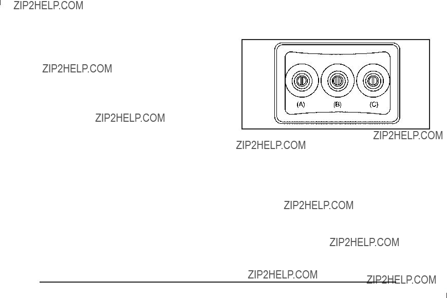
Notice: Do not store the headphones in heat or direct sunlight. This could damage the headphones and repairs will not be covered by the warranty. Storage in extreme cold can weaken the batteries. Keep the headphones stored in a cool, dry place.
If the foam ear pads attached to the headphones become worn or damaged, the pads can be replaced separately from the headphone set. See your dealer/retailer for more information.
Battery Replacement
To change the batteries on the headphones:
1.Turn the screw to loosen the battery door located on the left side of the headphones. Slide the battery door open.
2.Replace the two batteries in the compartment. Make sure that they are installed correctly, using the diagram on the inside of the battery compartment.
3.Replace the battery door and tighten the door screw.
If the headphones are to be stored for a long period of time, remove the batteries and keep them in a cool, dry place.
Audio/Video (A/V) Jacks
The A/V jacks, located on the rear of the ???oor console, allow audio or video signals to be connected from
an auxiliary device such as a camcorder or a video game unit to the RSE system. Adapter connectors
or cables (not included) might be required to connect the auxiliary device to the A/V jacks. Refer to the manufacturer???s instructions for proper usage.
The A/V jacks are color coded to match typical home entertainment system equipment. The yellow jack (A) is for the video input. The white jack (B) is for the left audio input. The red jack (C) is for the right audio input.
Power for auxiliary devices is not supplied by the radio system.

To use the auxiliary inputs of the RSE system, connect an external auxiliary device to the
by sourcing to auxiliary. See Radio(s) on page
How to Change the RSE Video Screen Settings
The screen display mode (normal, full, and zoom), screen brightness, and setup menu language can be changed from the on screen setup menu. To change any feature:
1.Press the z (display menu) button on the remote control.
2.Use the remote control n , q , p , o (navigation) arrows and the r (enter) button to use the
setup menu.
3.Press the z button again to remove the setup menu from the screen.
Audio Output
Audio from the DVD player or auxiliary inputs can be heard through the following possible sources:
???Wireless Headphones
???Vehicle Speakers
???Vehicle wired headphone jacks on the rear seat audio system, if the vehicle has this feature.
The RSE system always transmits the audio signal to the wireless headphones, if there is audio available. See ???Headphones??? earlier in this section for more information.
The DVD player is capable of outputting audio to the wired headphone jacks on the RSA system, if the vehicle has this feature. The DVD player can be selected as an audio source on the RSA system. See
Rear Seat Audio (RSA) on page
When a device is connected to the A/V jacks, or the radio???s auxiliary input jack, if the vehicle has this feature, the rear seat passengers are able to hear audio from the auxiliary device through the wireless or wired headphones. The front seat passengers are able to listen to playback from this device through the vehicle speakers by selecting AUX as the source on the radio.

Video Screen(s)
The video screen(s) are located in the overhead console.
To use the video screen(s):
1.Push the release button located on the overhead console.
2.Move the screen to the desired position.
When the video screen is not in use, push it up into its locked position.
If a DVD is playing and the screen is raised to its locked position, the screen remains on, this is normal, and
the DVD continues to play through the previous audio source. Use the remote control power button or eject the disc to turn off the screen.
The overhead console contains the infrared transmitters for the wireless headphones and the infrared receivers for the remote control. They are located at the rear
of the console.
Notice: Avoid directly touching the video screen, as damage may occur. See ???Cleaning the Video Screen??? later in this section for more information.
Remote Control
To use the remote control, aim it at the transmitter window at the rear of the overhead console and press the desired button. Direct sunlight or very bright light could affect the ability of the RSE transmitter to receive signals from the remote control. If the remote control does not seem to be working, the batteries might need to be replaced. See ???Battery Replacement??? later in
this section. Objects blocking the line of sight could also affect the function of the remote control.
If a CD or DVD is in the Radio DVD slot, the remote control power button can be used to turn on the video screen display and start the disc. The radio can also turn on the video screen display. See Radio(s) on page
Notice: Storing the remote control in a hot area or in direct sunlight can damage it, and the repairs will not be covered by the warranty. Storage
in extreme cold can weaken the batteries. Keep the remote control stored in a cool, dry place.
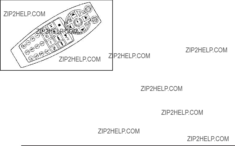
Remote Control Buttons
O (Power): Press this button to turn the video screen on and off.
P (Illumination): Press this button to turn the remote control backlight on. The backlight automatically
turns off after seven to ten seconds if no other button is pressed while the backlight is on.
v (Title): Press this button to return the DVD to the main menu of the DVD. This function may vary for each disc.
y (Main Menu): Press this button to access the DVD menu. The DVD menu is different on every DVD.
Use the navigation arrows to move the cursor around the DVD menu. After making a selection press the enter button. This button only operates when using a DVD.
n, q, p, o (Menu Navigation Arrows): Use the arrow buttons to navigate through a menu.
r (Enter): Press this button to select the choice that is highlighted in any menu.
z (Display Menu): Press this button to adjust the brightness, screen display mode (normal, full, or zoom), and display the language menu.
q (Return): Press this button to exit the current active menu and return to the previous menu. This button operates only when the display menu or a DVD menu is active.
c (Stop): Press this button to stop playing, fast reversing, or fast forwarding a DVD. Press this button twice to return to the beginning of the DVD.
s (Play/Pause): Press this button to start playing a DVD. Press this button while a DVD is playing to pause it. Press it again to continue playing the DVD.
On some radios, play may be slowed down by pressing the play/pause button then pressing the fast forward button when the DVD is playing. The DVD continues playing in a slow play mode. Some radios may perform reverse slow play by pressing the play/pause button and then pressing the fast reverse button. To cancel slow play mode, press the play/pause button.
t (Previous Track/Chapter): Press this button to return to the start of the current track or chapter. Press this button again to go to the previous track or chapter. This button might not work when the DVD is playing the copyright information or the previews.
u (Next Track/Chapter): Press this button to go to the beginning of the next chapter or track. This button might not work when the DVD is playing the copyright information or the previews.
r (Fast Reverse): Press this button to fast reverse the DVD or CD. To stop fast reversing a DVD video, press the play button. To stop fast reversing a
DVD audio or CD, release this button. This button might not work when the DVD is playing the copyright information or the previews.
[ (Fast Forward): Press this button to fast forward the DVD or CD. To stop fast forwarding a DVD video, press the play/pause button. To stop fast
forwarding a DVD audio or CD, release this button. This button might not work when the DVD is playing the copyright information or the previews.
e (Audio): Press this button to change audio tracks on DVDs that have this feature when the DVD is playing. The format and content of this function vary for
each disc.
{ (Subtitles): Press this button to turn ON/OFF subtitles and to move through subtitle options when a DVD is playing. The format and content of this function vary for each disc.
AUX (Auxiliary): Press this button to switch the system between the DVD player and an auxiliary source.
d (Camera): Press this button to change camera angles on DVDs that have this feature when a DVD is playing. The format and content of this function vary for each disc.
1 through 0 (Numeric Keypad): The numeric keypad provides the capability of direct chapter or track number selection.

\ (Clear): Press this button within three seconds after entering a numeric selection, to clear all numerical inputs.
} 10 (Double Digit Entries): Press this button to select chapter or track numbers greater than nine. Press this button before entering the number.
If the remote control becomes lost or damaged, a new universal remote control can be purchased. If this happens, make sure the universal remote control uses a code set of Toshiba??.
Battery Replacement
To change the remote control batteries:
1.Slide the rear cover back on to the remote control.
2.Replace the two batteries in the compartment. Make sure that they are installed correctly, using the diagram on the inside of the battery compartment.
3.Replace the battery cover.
If the remote control is to be stored for a long period of time, remove the batteries and keep them in a cool, dry place.

DVD Display Error Messages
The DVD display error message depends on which radio is in the vehicle. The video screen can display one of the following:
Disc Load/Eject Error: Displays when there are disc load or eject problems.
Disc Format Error: Displays if the disc is inserted with the disc label wrong side up, or if the disc is damaged.
Disc Region Error: Displays if the disc is not from a correct region.
No Disc Inserted: Displays if no disc is present when EJECT or DVD AUX is pressed on the radio.
DVD Distortion
Video distortion can occur when operating cellular phones, scanners, CB radios, Global Position Systems (GPS)*,
It might be necessary to turn off the DVD player when operating one of these devices in or near the vehicle.
*Excludes the OnStar?? System.
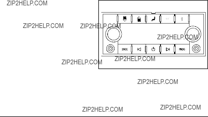
Cleaning the RSE Overhead Console
When cleaning the RSE overhead console surface, use only a clean cloth dampened with clean water.
Cleaning the Video Screen
When cleaning the video screen, use only a clean cloth dampened with clean water. Use care when directly touching or cleaning the screen, as damage could result.
Rear Seat Audio (RSA)
Vehicles with this feature allow the rear seat passengers to listen to and control any of the music sources:
radio, CDs, DVDs, or other auxiliary sources. However, the rear seat passengers can only control the music sources the front seat passengers are not listening to (except on some radios where dual control is allowed). For example, rear seat passengers can control and listen to a CD through the headphones, while the driver listens to the radio through the front speakers. The rear seat passengers have control of the volume
for each set of headphones.
The RSA functions operate even when the main radio is off. The front audio system will display the headphone icon when the RSA is on, and will disappear from
the display when it is off.
Audio can be heard through wired headphones (not included) plugged into the jacks on the RSA. If the vehicle has this feature, audio can also be heard on Channel 2 of the wireless headphones.
The audio system mutes the rear speakers when the RSA audio is active through the headphones.
P (Power): Press the P button to turn the RSA on or off.
Volume: Turn this knob to increase or to decrease the volume of the wired headphones. The left knob controls the left headphones and the right knob controls the right headphones.
SRCE (Source): Press this button to switch between the radio (AM/FM), XM??? (if equipped), CD, and if
the vehicle has these features, DVD, front auxiliary, and rear auxiliary.
?? ??(Seek): When listening to FM, AM, or XM???
(if equipped), press the left ??or right ?? seek arrow to go to the previous or to the next station or channel
and stay there. This function is inactive, with some radios, if the front seat passengers are listening to the radio.
Press and hold the left ??or right ?? seek arrow until the display ???ashes, to tune to an individual station. The display stops ???ashing after the buttons have not been pushed for more than two seconds. This function is inactive, with some radios, if the front seat passengers are listening to the radio.
While listening to a disc, press the left ?? seek arrow to go back to the start of the current track or chapter
(if more than ten seconds have played). Press the right ??seek arrow to go to the next track or chapter
on the disc. This function is inactive, with some radios, if the front seat passengers are listening to the disc.
When a DVD video menu is being displayed, press the left ??or right ?? seek arrow to perform a cursor up or down on the menu. Hold the left ??or right ?? arrow to perform a cursor left or right on the menu.
PROG (Program): Press this button to go to the next preset radio station or channel set on the main
radio. This function is inactive, with some radios, if the front seat passengers are listening to the radio.
When a CD or DVD audio disc is playing, press this button to go to the beginning of the CD or DVD audio. This function is inactive, with some radios, if the
front seat passengers are listening to the disc.
When a disc is playing in the CD or DVD changer, press this button to select the next disc, if multiple discs are loaded. This function is inactive, with some radios, if the front seat passengers are listening to the disc.
When a DVD video menu is being displayed, press the PROG button to perform the menu function, enter.

THEFTLOCK?? is designed to discourage theft of the vehicle???s radio by learning a portion of the Vehicle Identi???cation Number (VIN). The radio does not operate if it is stolen or moved to a different vehicle.
Audio Steering Wheel Controls
Vehicles with audio steering wheel controls could differ depending on the vehicle???s options. Some audio controls can be adjusted at the steering wheel.
w (Next): Press to go to the next radio station stored as a favorite, or the next track if a CD/DVD is playing.
x c (Previous/End): Press to go to the previous radio station stored as a favorite, the next track if
a CD/DVD is playing, to reject an incoming call, or end a current call.
b g (Mute/Push to Talk): Press to silence the vehicle speakers only. Press again to turn the sound on.
For vehicles with OnStar?? or Bluetooth?? systems press and hold b g for longer than two seconds to interact with those systems. See OnStar?? System on page
more information.
SRCE (Source/Voice Recognition): Press to switch between the radio (AM, FM, XM), CD, DVD (if equipped), front auxiliary (if equipped), and rear auxiliary
(if equipped).
For vehicles with the navigation system, press and hold this button for longer than one second to initiate voice recognition. See ???Voice Recognition??? in the Navigation System manual for more information.
+ e ??? e (Volume): Press to increase or to decrease the radio volume.