2009 Chevrolet HHR Owner Manual M
2009 Chevrolet HHR Owner Manual M

GENERAL MOTORS, GM, the GM Emblem, CHEVROLET, the CHEVROLET Emblem, and the name HHR are registered trademarks of General Motors Corporation.
This manual includes the latest information at the time it was printed. GM reserves the right to make changes after that time without further notice. For vehicles ???rst sold in Canada, substitute the name ???General Motors of Canada Limited??? for Chevrolet Motor Division wherever it appears in this manual.
This manual describes features that may or may not be on your speci???c vehicle.
Read this manual from beginning to end to learn about the vehicle???s features and controls. Pictures, symbols, and words work together to explain vehicle operation.
Keep this manual in the vehicle for quick reference.
Litho in U.S.A.
Part No. 25778495 B Second Printing
Canadian Owners
A French language copy of this manual can be obtained from your dealer/retailer or from:
Helm, Incorporated
P.O. Box 07130
Detroit, MI 48207
Propri??taires Canadiens
On peut obtenir un exemplaire de ce guide en fran??ais aupr??s de concessionnaire ou ?? l???adresse suivante:
Helm, Incorporated
P.O. Box 07130
Detroit, MI 48207
Index
To quickly locate information about the vehicle, use the index in the back of the manual. It is an alphabetical list of what is in the manual and the page number where it can be found.
?? 2008 General Motors Corporation. All Rights Reserved.
ii

Safety Warnings and Symbols
A circle with a slash through it is a safety symbol which means ???Do Not,??? ???Do not do this,??? or ???Do not let this happen.???
A box with the word CAUTION is used to tell about things that could hurt you or others if you were to ignore the warning.
{ CAUTION:
These mean there is something that could hurt you or other people.
Cautions tell what the hazard is and what to do to avoid or reduce the hazard. Read these cautions.
A notice tells about something that can damage the vehicle.
Notice: These mean there is something that could damage your vehicle.
Many times, this damage would not be covered by the vehicle???s warranty, and it could be costly. The notice tells what to do to help avoid the damage.
There are also warning labels on the vehicle which use the same words, CAUTION or Notice.
Vehicle Symbols
The vehicle has components and labels that use symbols instead of text. Symbols are shown along with the text describing the operation or information relating to a speci???c component, control, message, gage, or indicator.
M : This symbol is shown when you need to see your owner manual for additional instructions or information.
* : This symbol is shown when you need to see a service manual for additional instructions or information.
iii

Vehicle Symbol Chart
Here are some additional symbols that may be found on the vehicle and what they mean. For more information on the symbol, refer to the index.
9 : Airbag Readiness Light
# : Air Conditioning
! : Antilock Brake System (ABS)
g : Audio Steering Wheel Controls or OnStar??
$ : Brake System Warning Light
" : Charging System
I : Cruise Control
B : Engine Coolant Temperature
O : Exterior Lamps
# : Fog Lamps
. : Fuel Gage
+ : Fuses
i : Headlamp
j : LATCH System Child Restraints
* : Malfunction Indicator Lamp
: : Oil Pressure
} : Power
/ : Remote Vehicle Start
> : Safety Belt Reminders
7 : Tire Pressure Monitor
F : Traction Control
M : Windshield Washer Fluid
iv

Section 1 Seats and Restraint System

Front Seats
Manual Seats
{ CAUTION:
You can lose control of the vehicle if you try to adjust a manual driver???s seat while the vehicle is moving. The sudden movement could startle and confuse you, or make you push a pedal when you do not want to. Adjust the driver???s seat only when the vehicle is not moving.
If the vehicle has a manual seat, it can be moved forward or rearward.
1. Lift the bar to unlock the seat.
2. Slide the seat to the desired position and release the bar.
Try to move the seat with your body to be sure the seat is locked in place.

If your vehicle has this feature, the driver???s seat height adjuster is located on the outboard side of the seat.
To raise the seat, move the lever upward repeatedly until the seat is at the desired height. To lower the seat, move the lever downward repeatedly until the seat is
at the desired height.
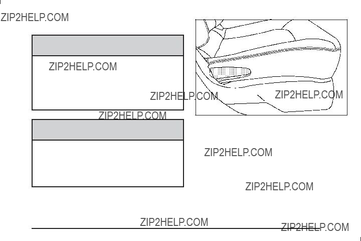
Driver???s Seat with Power Seat Control and Power Lumbar shown
If the vehicle has a power seat, the control used to operate it is located on the outboard side of the driver???s seat. To adjust the seat, do any of the following:
???Move the seat forward or rearward by sliding the control forward or rearward.
???Raise or lower the front part of the seat cushion by holding the front of the control up or down.
???Raise or lower the entire seat by holding the rear of the control up or down.

If your vehicle has this feature, the control is located on the outboard side of the driver???s seat cushion.
To increase support, press and hold the front of the control. To decrease support, press and hold the rear of the control. Keep in mind that as your seating position changes, as it may during long trips, so should the position of your lumbar support. Adjust the seat as needed.
If your vehicle has this feature, the driver???s and passenger???s heated seat buttons are located on the climate control
panel below the fan switch.
Driver???s side button shown, Passenger???s side button similar
Press the button once to turn the heated seat to the high setting. Both lights below the heated seat symbol will come on. Press the button a second time and the heated seat will go to the low setting. The bottom light will come on to indicate that the setting is on low. Press the button a third time to turn the heated seat off.
The heated seat feature will need to be turned on each time the ignition is turned off and back on again.
Reclining Seatbacks
{ CAUTION:
You can lose control of the vehicle if you try to adjust a manual driver???s seat while the vehicle is moving. The sudden movement could startle and confuse you, or make you push a pedal when you do not want to. Adjust the driver???s seat only when the vehicle is not moving.
{ CAUTION:
If either seatback is not locked, it could move forward in a sudden stop or crash. That could cause injury to the person sitting there. Always push and pull on the seatbacks to be sure they are locked.
Passenger???s Side Reclining Lever shown, Driver???s Side similar
The seats have reclining seatbacks. The lever used to operate them is located on the outboard side of the seats. Lift the lever to release the seatback. Move the seatback to where you want it and release the lever to lock the seatback in place. Press rearward on
the seatback to be sure it is locked into place.

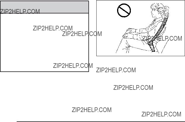
{ CAUTION:
Sitting in a reclined position when the vehicle is in motion can be dangerous. Even when buckled up, the safety belts cannot do their job when reclined like this.
The shoulder belt cannot do its job because it will not be against your body. Instead, it will be in front of you. In a crash, you could go into it, receiving neck or other injuries.
The lap belt cannot do its job either. In a crash, the belt could go up over your abdomen. The belt forces would be there, not at your pelvic bones. This could cause serious internal injuries.
For proper protection when the vehicle is in motion, have the seatback upright. Then sit well back in the seat and wear the safety belt properly.
Do not have a seatback reclined if your vehicle is moving.
Head Restraints
Adjust the head restraint so that the top of the restraint is at the same height as the occupant???s head. This position reduces the chance of a neck injury in a crash.
Pull the head restraint up to raise it. To lower the head restraint, press
the button, located on the top of the seatback, and push the restraint down. Only the front head restraints are adjustable.
Both the front and rear head restraints can be removed. Press the button, located on the top of the seatback, and pull the restraint out from the seatback. Do not remove the head restraint if someone will be sitting in that seat while the vehicle is moving.

Passenger Folding Seatback
Your vehicle has a front passenger seat that folds ???at.
{ CAUTION:
If you fold the seatback forward to carry longer objects, such as skis, be sure any such cargo is not near an airbag. In a crash, an in???ating airbag might force that object toward a person. This could cause severe injury or even death. Secure objects
CAUTION: (Continued)
CAUTION: (Continued)
away from the area in which an airbag would in???ate. For more information, see Where Are the Airbags? on page
{ CAUTION:
Things you put on this seatback can strike and injure people in a sudden stop or turn, or in a crash. Remove or secure all items before driving.

To fold the seatback, do the following:
1.Move the front passenger seat rearward to ensure there is enough room to fold the seatback forward. See Manual Seats on page
the seat is not able to be moved fully rearward. If removing the head restraint, store it so that it will not move while the vehicle is in motion.
2.Make sure that the seatback is in an upright position. Use the recliner lever located on the outboard side of the seat to move the seatback to the upright position.
3. To fold the seat ???at, pull up on either lever located toward the rear of the seatback. Fold the seat forward until the seatback disengages.
4. Continue to fold the seat forward until it locks in the folded position. Pull up on the seatback to be sure it is locked.

To raise the seatback to an upright position:
1.Pull up on either lever.
2.Push the seatback up until it is in a locked position.
{CAUTION:
If either seatback is not locked, it could move forward in a sudden stop or crash. That could cause injury to the person sitting there. Always push and pull on the seatbacks to be sure they are locked.
3.Push and pull on the seatback to make sure it is locked.
Rear Seats
Split Folding Rear Seat
The seatbacks can be folded ???at.
To lower the rear seatback(s):
1.Move the front seat forward and/or put the front seatback in an upright position so it does not interfere with folding the rear seatback forward.
2.Open the rear door while the vehicle is parked.
3.The rear head restraint may need to be removed if it interferes with the front seat when the front seat is moved back in place. If removed, store the head restraint where it cannot move while the vehicle is in motion.
Notice: Folding a rear seat with the safety belts still fastened may cause damage to the seat or the safety belts. Always unbuckle the safety belts and return them to their normal stowed position before folding a rear seat.

5. Pull up on the knob located on the top of the seatback on
the outboard side to release the seatback.
4.Move the safety belt out of the way before lowering the seatback. Do not let the safety belt get caught between the seatback and seat cushion as the seatback is folded.

To raise the rear seatback(s):
{ CAUTION:
A safety belt that is improperly routed, not properly attached, or twisted will not provide the protection needed in a crash. The person wearing the belt could be seriously injured. After raising the rear
CAUTION: (Continued)
CAUTION: (Continued)
seatback, always check to be sure that the
safety belts are properly routed and attached, and are not twisted.
6.Lift the seatback up and push rearward until you hear a click. Keep the safety belt clear of the seat and not twisted.
The release knob on the top of the seatback has a red ring. If the seatback is not fully latched this ring will be visible. Push on the seatback until the ring is not visible.
{CAUTION:
If the seatback is not locked, it could move forward in a sudden stop or crash. That could cause injury to the person sitting there. Always pull forward on the top of the seatback at the area of the latch to be sure it is locked.
7.Push and pull on the seatback to make sure it is locked in place.

Safety Belts
Safety Belts: They Are for Everyone
This section of the manual describes how to use safety belts properly. It also describes some things not to do with safety belts.
{ CAUTION:
Do not let anyone ride where a safety belt cannot be worn properly. In a crash, if you or your passenger(s) are not wearing safety belts, the injuries can be much worse. You can hit things inside the vehicle harder or be ejected from the vehicle. You and your passenger(s) can be seriously injured or killed. In the same crash, you might not be, if you are buckled up. Always fasten your safety belt, and check that your passenger(s) are restrained properly too.
{ CAUTION:
It is extremely dangerous to ride in a cargo area, inside or outside of a vehicle. In a collision, people riding in these areas are more likely to be seriously injured or killed. Do not allow people to ride in any area of your vehicle that is not equipped with seats and safety belts. Be sure everyone in your vehicle is in a seat and using a safety belt properly.
This vehicle has indicators as a reminder to buckle the safety belts. See Safety Belt Reminders on page
In most states and in all Canadian provinces, the law requires wearing safety belts. Here is why:
You never know if you will be in a crash. If you do have a crash, you do not know if it will be a serious one.
A few crashes are mild, and some crashes can be so serious that even buckled up, a person would not survive. But most crashes are in between. In many of them, people who buckle up can survive and sometimes walk away. Without safety belts, they could have been badly hurt or killed.
After more than 40 years of safety belts in vehicles, the facts are clear. In most crashes buckling up does matter... a lot!

Why Safety Belts Work
When you ride in or on anything, you go as fast as it goes.
Put someone on it.
Take the simplest vehicle. Suppose it is just a seat on wheels.

Get it up to speed. Then stop the vehicle. The rider does not stop.
The person keeps going until stopped by something.
In a real vehicle, it could be the windshield...

Questions and Answers About Safety
Belts
Q:
A: You could be ??? whether you are wearing a safety belt or not. But your chance of being conscious during and after an accident, so you can unbuckle and get out, is much greater if you are belted.
And you can unbuckle a safety belt, even if you are upside down.
Q:
A: Airbags are supplemental systems only; so they work with safety belts ??? not instead of them. Whether or not an airbag is provided, all occupants still have to buckle up to get the most protection. That is true not only in frontal collisions, but especially in side and other collisions.
Q: If I am a good driver, and I never drive far from home, why should I wear safety belts?
A: You may be an excellent driver, but if you are in a crash ??? even one that is not your fault ??? you and your passenger(s) can be hurt. Being a good driver does not protect you from things beyond your control, such as bad drivers.
Most accidents occur within 25 miles (40 km) of home. And the greatest number of serious injuries and deaths occur at speeds of less than 40 mph (65 km/h).
Safety belts are for everyone.

How to Wear Safety Belts Properly
This section is only for people of adult size.
Be aware that there are special things to know about safety belts and children. And there are different rules for smaller children and infants. If a child will be riding in the vehicle, see Older Children on page
It is very important for all occupants to buckle up. Statistics show that unbelted people are hurt more often in crashes than those who are wearing safety belts.
Occupants who are not buckled up can be thrown out of the vehicle in a crash. And they can strike others in
the vehicle who are wearing safety belts.
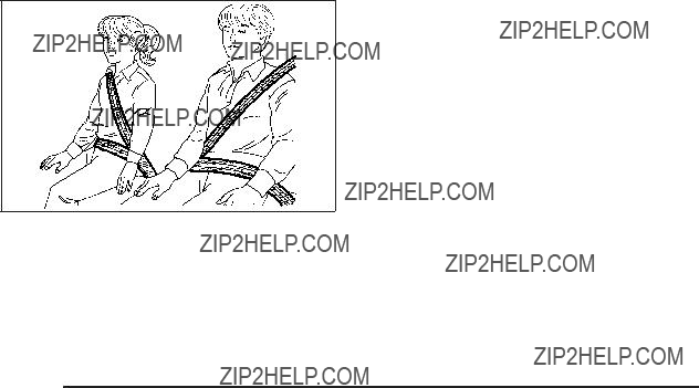
First, before you or your passenger(s) wear a safety belt, there is important information you should know.
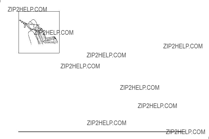
Sit up straight and always keep your feet on the ???oor in front of you. The lap part of the belt should be worn low and snug on the hips, just touching the thighs. In a crash, this applies force to the strong pelvic bones and you would be less likely to slide under the lap belt. If you slid under it, the belt would apply force on your abdomen. This could cause serious or even fatal injuries. The shoulder belt should go over the shoulder and across the chest. These parts of the body are best able to take belt restraining forces.
The shoulder belt locks if there is a sudden stop or crash.

Q: What is wrong with this?
A: The shoulder belt is too loose. It will not give as much protection this way.
{ CAUTION:
You can be seriously hurt if your shoulder belt is too loose. In a crash, you would move forward too much, which could increase injury. The shoulder belt should ???t snugly against your body.

Q: What is wrong with this?
A: The lap belt is too loose. It will not give nearly as much protection this way.
{ CAUTION:
You can be seriously hurt if your lap belt is too loose. In a crash, you could slide under the lap belt and apply force on your abdomen. This could cause serious or even fatal injuries. The lap belt should be worn low and snug on the hips, just touching the thighs.

Q: What is wrong with this?
A: The belt is buckled in the wrong buckle.
{ CAUTION:
You can be seriously injured if your belt is buckled in the wrong place like this. In a crash, the belt would go up over your abdomen. The belt forces would be there, not on the pelvic bones. This could cause serious internal injuries. Always buckle your belt into the buckle nearest you.

Q: What is wrong with this?
{ CAUTION:
You can be seriously injured if your belt goes over an armrest like this. The belt would be much too high. In a crash, you can slide under the belt. The belt force would then be applied on the abdomen, not on the pelvic bones, and that could cause serious or fatal injuries. Be sure the belt goes under the armrests.
A: The belt is over an armrest.

Q: What is wrong with this?
A: The shoulder belt is worn under the arm. It should be worn over the shoulder at all times.
{ CAUTION:
You can be seriously injured if you wear the shoulder belt under your arm. In a crash, your body would move too far forward, which would increase the chance of head and neck injury. Also, the belt would apply too much force to the ribs, which are not as strong as shoulder bones. You could also severely injure internal organs like your liver or spleen. The shoulder belt should go over the shoulder and across the chest.

Q: What is wrong with this?
{ CAUTION:
You can be seriously injured by not wearing the
A: The belt is behind the body.

Q: What is wrong with this?
A: The belt is twisted across the body.
{ CAUTION:
You can be seriously injured by a twisted belt. In a crash, you would not have the full width of the belt to spread impact forces. If a belt is twisted, make it straight so it can work properly, or ask your dealer/retailer to ???x it.

All seating positions in the vehicle have a
The following instructions explain how to wear a
1.Adjust the seat, if the seat is adjustable, so you can sit up straight. To see how, see ???Seats??? in the Index.
2.Pick up the latch plate and pull the belt across you. Do not let it get twisted.
The
If the shoulder portion of a passenger belt is pulled out all the way, the child restraint locking feature may be engaged. If this happens, let the belt
go back all the way and start again.
Engaging the child restraint locking feature may affect the passenger sensing system. See Passenger Sensing System (Without Turbo/With Turbo and RPO AS5) on page
page
3.Push the latch plate into the buckle until it clicks.
Pull up on the latch plate to make sure it is secure. If the belt is not long enough, see Safety Belt Extender on page
Position the release button on the buckle so that the safety belt could be quickly unbuckled if necessary.
4.If equipped with a shoulder belt height adjuster, move it to the height that is right for you. See ???Shoulder Belt Height Adjustment??? later in this section for use and important safety information.
5.To make the lap part tight, pull up on the shoulder belt.
It may be necessary to pull stitching on the safety belt through the latch plate to fully tighten the
lap belt on smaller occupants.
To unlatch the belt, push the button on the buckle. The belt should return to its stowed position.
Before a door is closed, be sure the safety belt is out of the way. If a door is slammed against a safety belt, damage can occur to both the safety belt and the vehicle.
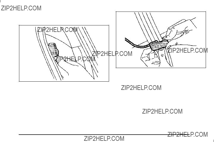
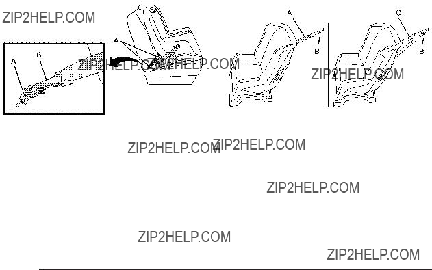
Shoulder Belt Height Adjuster
The vehicle has a shoulder belt height adjuster for the driver and right front passenger seating positions.
Adjust the height so that the shoulder portion of the belt is centered on the shoulder. The belt should be away from the face and neck, but not falling off the shoulder. Improper shoulder belt height adjustment could
reduce the effectiveness of the safety belt in a crash.
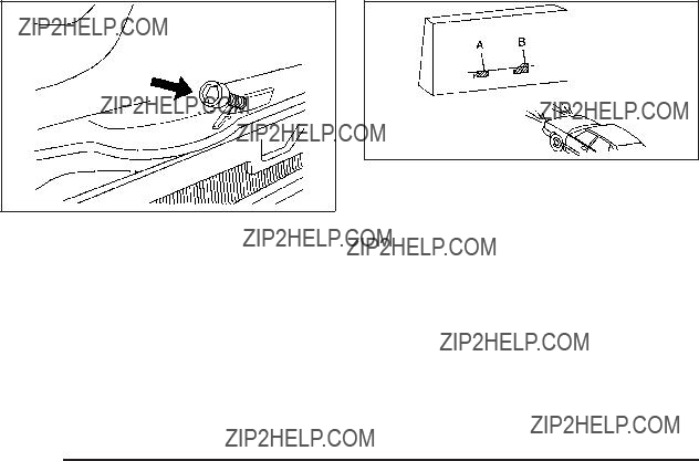
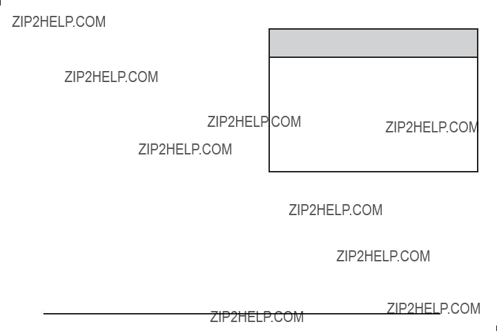
Push down on the release button (A) and move
the height adjuster to the desired position.
The adjuster can be moved up by pushing the release button up on the shoulder belt guide.
After the height adjuster is set to the desired position, try to move it down without pressing the release button to make sure it has locked into position.
Safety Belt Pretensioners
This vehicle has safety belt pretensioners for front outboard occupants. Although the safety belt
pretensioners cannot be seen, they are part of the safety belt assembly. They can help tighten the safety belts during the early stages of a moderate to severe frontal or near frontal crash if the threshold conditions for pretensioner activation are met. And, if the vehicle has side impact airbags, safety belt pretensioners can help tighten the safety belts in a side crash and rear events.
Pretensioners work only once. If the pretensioners activate in a crash, They will need to be replaced, and probably other new parts for the vehicle???s safety belt system. See Replacing Restraint System Parts After a Crash on page
Rear Safety Belt Comfort Guides
Rear shoulder belt comfort guides may provide added safety belt comfort for older children who have outgrown booster seats and for some adults. When installed on
a shoulder belt, the comfort guide positions the shoulder belt away from the neck and head.
There is one guide for each outboard passenger position in the rear seat. Here is how to install a comfort guide to the safety belt:
1.Pull the elastic cord out from between the edge of the seatback and the interior body to remove the guide from its storage clip.
2.Place the guide over the belt and insert the two edges of the belt into the slots of the guide.

3.Be sure that the belt is not twisted and it lies ???at. The elastic cord must be under the belt and the guide on top.
{CAUTION:
A safety belt that is not properly worn may not provide the protection needed in a crash. The person wearing the belt could be seriously injured. The shoulder belt should go over the shoulder and across the chest. These parts of the body are best able to take belt restraining forces.
4.Buckle, position, and release the safety belt as described previously in this section. Make sure that the shoulder belt crosses the shoulder.
To remove and store the comfort guide, squeeze the belt edges together so that the safety belt can be removed from the guide. Pull the guide upward to expose its storage clip, and then slide the guide onto the clip. Turn the guide and clip inward and slide them in between the seatback and the interior body, leaving only the loop of the elastic cord exposed.

Safety Belt Use During Pregnancy
Safety belts work for everyone, including pregnant women. Like all occupants, they are more likely to be seriously injured if they do not wear safety belts.
A pregnant woman should wear a
The best way to protect the fetus is to protect the mother. When a safety belt is worn properly, it is more likely that the fetus will not be hurt in a crash. For pregnant women, as for anyone, the key to making safety belts effective is wearing them properly.
Safety Belt Extender
If the vehicle???s safety belt will fasten around you, you should use it.
But if a safety belt is not long enough, your dealer/retailer will order you an extender. When you go in to order it, take the heaviest coat you will wear, so the extender will be long enough for you. To help avoid personal injury, do not let someone else use it, and use it only for the seat it is made to ???t. The extender has been designed for adults. Never use it for securing child seats. To wear it, attach it to the regular safety belt. For more information, see the instruction sheet that comes with the extender.
Child Restraints
Older Children
Older children who have outgrown booster seats should wear the vehicle???s safety belts.
The manufacturer???s instructions that come with the booster seat state the weight and height limitations for that booster. Use a booster seat with a
???Sit all the way back on the seat. Do the knees bend at the seat edge? If yes, continue. If no, return to the booster seat.
???Buckle the
???Does the lap belt ???t low and snug on the hips, touching the thighs? If yes, continue. If no, return to the booster seat.
???Can proper safety belt ???t be maintained for the length of the trip? If yes, continue. If no, return to the booster seat.
???If you have the choice, a child should sit in a position with a

Q: What is the proper way to wear safety belts?
A: An older child should wear a
Also see ???Rear Safety Belt Comfort Guides??? under
According to accident statistics, children and infants are safer when properly restrained in a child restraint system or infant restraint system secured in a rear seating position.
In a crash, children who are not buckled up can strike other people who are buckled up, or can be thrown out of the vehicle. Older children need to use safety belts properly.
{ CAUTION:
Never do this.
Never allow two children to wear the same safety belt. The safety belt can not properly spread the impact forces. In a crash, the two children can be crushed together and seriously injured. A safety belt must be used by only one person at a time.
{ CAUTION:
Never do this.
Never allow a child to wear the safety belt with the shoulder belt behind their back. A child can be seriously injured by not wearing the

Infants and Young Children
Everyone in a vehicle needs protection! This includes infants and all other children. Neither the distance traveled nor the age and size of the traveler changes the need, for everyone, to use safety restraints. In fact, the law in every state in the United States and in every Canadian province says children up to some age must be restrained while in a vehicle.
{ CAUTION:
Children can be seriously injured or strangled if a shoulder belt is wrapped around their neck and the safety belt continues to tighten. Never leave children unattended in a vehicle and never allow children to play with the safety belts.
Airbags plus
Children who are not restrained properly can strike other people, or can be thrown out of the vehicle.

{ CAUTION:
Never do this.
Never hold an infant or a child while riding in a vehicle. Due to crash forces, an infant or a child will become so heavy it is not possible to hold it during a crash. For example, in a crash at only 25 mph (40 km/h), a 12 lb (5.5 kg) infant will suddenly become a 240 lb (110 kg) force on a person???s arms. An infant should be secured in an appropriate restraint.
{ CAUTION:
Never do this.
Children who are up against, or very close to, any airbag when it in???ates can be seriously injured or killed. Never put a

Q: What are the different types of
A:
be used.
For most basic types of child restraints, there are many different models available. When purchasing a child restraint, be sure it is designed to be used
in a motor vehicle. If it is, the restraint will have a label saying that it meets federal motor vehicle safety standards.
The restraint manufacturer???s instructions that come with the restraint state the weight and height limitations for a particular child restraint. In addition, there are many kinds of restraints available for children with special needs.
{ CAUTION:
To reduce the risk of neck and head injury during a crash, infants need complete support. This is because an infant???s neck is not fully developed and its head weighs so much compared with
the rest of its body. In a crash, an infant in a

{ CAUTION:
A young child???s hip bones are still so small that the vehicle???s regular safety belt may not remain low on the hip bones, as it should. Instead, it may settle up around the child???s abdomen. In a crash, the belt would apply force on a body area that is unprotected by any bony structure. This alone could cause serious or fatal injuries. To reduce the risk of serious or fatal injuries during a crash, young children should always be secured in appropriate child restraints.
Child Restraint Systems
A
seat (A) provides restraint with the seating surface against the back of
the infant.
The harness system holds the infant in place and, in a crash, acts to keep the infant positioned in the restraint.
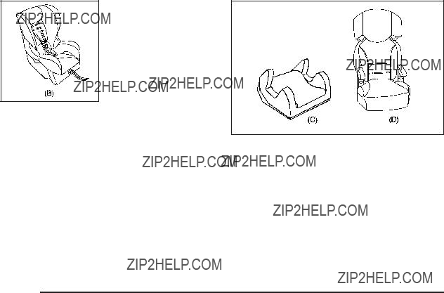
A
with the harness.
A booster seat

Securing an
the Vehicle
{ CAUTION:
A child can be seriously injured or killed in a crash if the child restraint is not properly secured in the vehicle. Secure the child restraint properly in the vehicle using the vehicle???s safety belt or LATCH system, following the instructions that came with that child restraint and the instructions in this manual.
To help reduce the chance of injury, the child restraint must be secured in the vehicle. Child restraint systems must be secured in vehicle seats by lap belts or the lap belt portion of a
When securing an
Keep in mind that an unsecured child restraint can move around in a collision or sudden stop and injure people in the vehicle. Be sure to properly secure
any child restraint in the vehicle ??? even when no child is in it.
Securing the Child Within the Child
Restraint
{ CAUTION:
A child can be seriously injured or killed in a crash if the child is not properly secured in the child restraint. Secure the child properly following the instructions that came with that child restraint.

Where to Put the Restraint
According to accident statistics, children and infants are safer when properly restrained in a child restraint system or infant restraint system secured in a rear seating position.
We recommend that children and child restraints be secured in a rear seat, including: an infant or a child riding in a
A label on the sun visor says, ???Never put a
to the
{ CAUTION:
A child in a
CAUTION: (Continued)
CAUTION: (Continued)
in???ating airbag. A child in a
Even if the passenger sensing system has turned off the right front passenger frontal airbag, no system is
Secure
See Passenger Sensing System (Without Turbo/ With Turbo and RPO AS5) on page

If the vehicle does not have a rear seat that will accommodate a
When securing a child restraint in a rear seating position, study the instructions that came with your child restraint to make sure it is compatible with this vehicle.
Wherever a child restraint is installed, be sure to secure the child restraint properly.
Keep in mind that an unsecured child restraint can move around in a collision or sudden stop and injure people in the vehicle. Be sure to properly secure any child restraint in the vehicle ??? even when no child is in it.
Lower Anchors and Tethers for Children (LATCH)
The LATCH system holds a child restraint during driving or in a crash. This system is designed to make installation of a child restraint easier. The LATCH system uses anchors in the vehicle and attachments on the child restraint that are made for use with the LATCH system.
Make sure that a
In order to use the LATCH system in your vehicle, you need a child restraint that has LATCH attachments. The child restraint manufacturer will provide you with instructions on how to use the child restraint and its attachments. The following explains how to attach a child restraint with these attachments in your vehicle.
Not all vehicle seating positions or child restraints have lower anchors and attachments or top tether anchors and attachments.
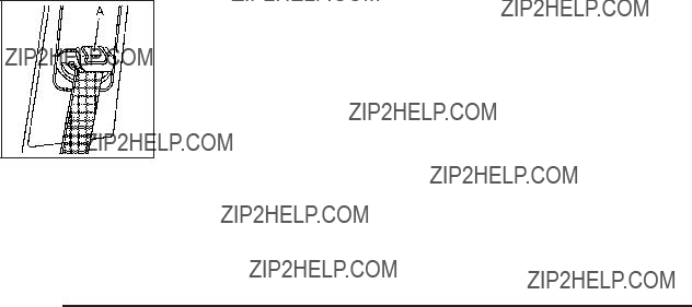
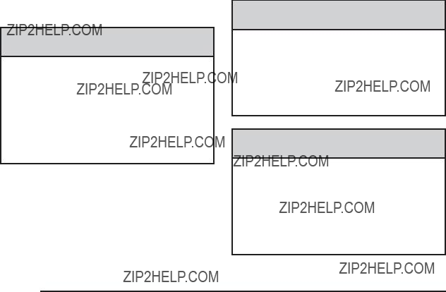
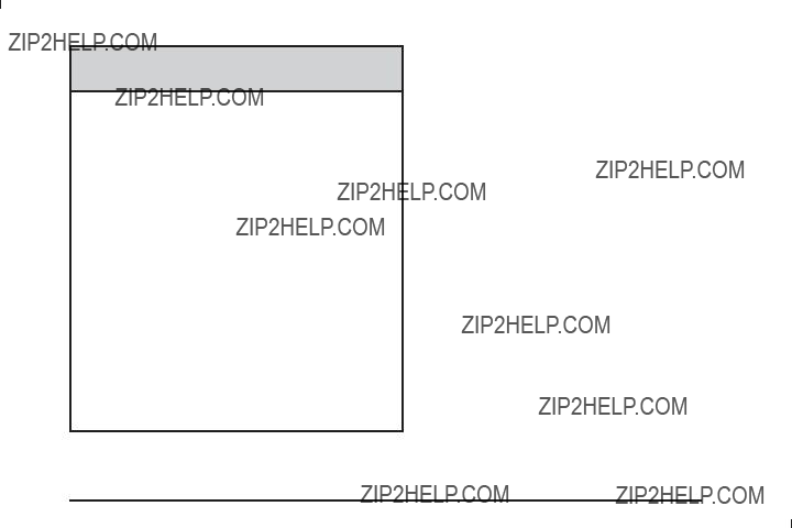
Lower anchors (A) are metal bars built into the vehicle. There are two lower anchors for each LATCH seating position that will accommodate a child restraint with lower attachments (B).
A top tether (A, C) anchors the top of the child restraint to the vehicle. A top tether anchor is built into the vehicle. The top tether attachment (B) on the child restraint connects to the top tether anchor in the vehicle in order to reduce the forward movement and rotation of the child restraint during driving or in a crash.
Your child restraint may have a single tether (A) or a dual tether (C). Either will have a single attachment (B) to secure the top tether to the anchor.

Some child restraints that have a top tether are designed for use with or without the top tether being attached. Others require the top tether always to be attached.
In Canada, the law requires that
If the child restraint does not have a top tether, one can be obtained, in kit form, for many child restraints. Ask the child restraint manufacturer whether or not a kit
is available.
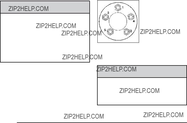
Lower Anchor and Top Tether Anchor
Locations
j (Lower Anchor): Seating positions with two lower anchors.
i (Top Tether Anchor): Seating positions with top tether anchors.
j (Lower Anchor): Seating positions with two lower anchors.
i (Top Tether Anchor): Seating positions with top tether anchors.
Front Passenger
Seat ??? Panel and Rear
Seat Delete Models
Rear Seat

To assist you in locating the lower anchors, each seating position with lower anchors has two labels, near the crease between the seatback and the seat cushion.
To assist you in locating the top tether anchors, this symbol will be located on the lower side quarter panels for the rear outboard positions, on the storage compartment for the rear center position and on the cargo mat behind the rear seats.
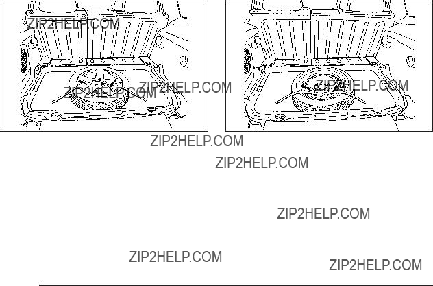
Vehicles with Rear Seats
The rear outboard top tether anchors are located on the cargo ???oor behind the rear seats.
The rear center top tether anchor is located in a storage compartment behind the rear seats. Lift the lid of the storage compartment to access the anchor. You may have to fold back the cargo mat to access the storage compartment and the top tether anchor for the rear center seating position.
Be sure to use an anchor located on the same side of the vehicle as the seating position where the child restraint will be placed.
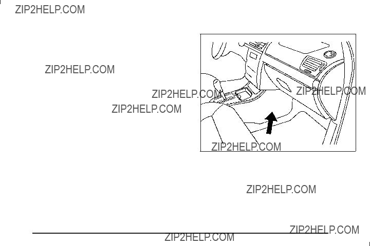
Vehicles without Rear Seats ??? Panel and Rear Seat Delete Models
If your vehicle does not have a rear seat, there will be an exposed top tether anchor for the front passenger position located on the rear passenger side pillar behind the front passenger seat.
Do not secure a child restraint in a position without a top tether anchor if a national or local law requires that the top tether be attached, or if the instructions that come with the child restraint say that the top tether must be attached.
Accident statistics show that children are safer if they are restrained in the rear rather than the front seat. See Where to Put the Restraint on page
Securing a Child Restraint Designed for the LATCH System
{ CAUTION:
If a
{ CAUTION:
Do not attach more than one child restraint to a single anchor. Attaching more than one child restraint to a single anchor could cause the anchor or attachment to come loose or even break during a crash. A child or others could be injured. To reduce the risk of serious or fatal injuries during a crash, attach only one child restraint per anchor.
{ CAUTION:
Children can be seriously injured or strangled if a shoulder belt is wrapped around their neck and the safety belt continues to tighten. Buckle any unused safety belts behind the child restraint so children cannot reach them. Pull the shoulder belt all the way out of the retractor to set the lock, if your vehicle has one, after the child restraint has been installed.

Notice: Do not let the LATCH attachments rub against the vehicle???s safety belts. This may damage these parts. If necessary, move buckled safety belts to avoid rubbing the LATCH attachments.
Do not fold the empty rear seat with a safety belt buckled. This could damage the safety belt or
the seat. Unbuckle and return the safety belt to its stowed position, before folding the seat.
1.Attach and tighten the lower attachments to the lower anchors. If the child restraint does not have lower attachments or the desired seating position does not have lower anchors, secure the child restraint with the top tether and the safety belts. Refer to your child restraint manufacturer instructions and the instructions in this manual.
1.1.Find the lower anchors for the desired seating position.
1.2.Put the child restraint on the seat.
1.3.Attach and tighten the lower attachments on the child restraint to the lower anchors.
2.If the child restraint manufacturer recommends that the top tether be attached, attach and tighten the top tether to the top tether anchor, if equipped. Refer to the child restraint instructions and
the following steps:
2.1.To secure a child restraint in the rear center seating position, ???nd the storage compartment behind the rear seats. You may have to fold back the cargo mat to access the storage compartment and the top tether anchor.
Lift the lid of the storage compartment to access the top tether anchor for the rear center seating position.
2.2.To secure a child restraint in the rear outboard seating positions, ???nd the top tether anchor located on the cargo ???oor behind the rear seats.
Be sure to use an anchor located on the same side of the vehicle as the seating position where the child restraint will
be placed.

2.3.To secure a child in the front passenger position, only if your vehicle does not have rear seats, ???nd the top tether anchor located on the rear passenger side pillar behind
the front passenger seat.
Be sure to use an anchor located on the same side of the vehicle as the seating position where the child restraint will be placed.
2.4.If the position you are using has an adjustable headrest or head restraint, raise it.
2.5.Route, attach, and tighten the top tether according to your child restraint instructions and the following instructions:
If the position you are using does not have a headrest or head restraint and you are using a single tether, route the tether over the seatback.
If the position you are using does not have a headrest or head restraint and you are using a dual tether, route the tether over the seatback.
If the position you are using has an adjustable headrest or head restraint and you are using a single tether, raise the headrest or head restraint and route the tether under the headrest or head restraint and in between the headrest or head restraint posts.
If the position you are using has an adjustable headrest or head restraint and you are using a dual tether, route the tether around the headrest or head restraint.
3.Push and pull the child restraint in different directions to be sure it is secure.
Securing a Child Restraint in a Rear
Seat Position
When securing a child restraint in a rear seating position, study the instructions that came with the child restraint to make sure it is compatible with this vehicle.
If the child restraint has the LATCH system, see Lower Anchors and Tethers for Children (LATCH) on page
Do not secure a child seat in a position without a top tether anchor if a national or local law requires that the top tether be anchored, or if the instructions that come with the child restraint say that the top strap must be anchored.
In Canada, the law requires that
If the child restraint does not have the LATCH system, you will be using the safety belt to secure the child restraint in this position. Be sure to follow the instructions that came with the child restraint. Secure the child in the child restraint when and as the instructions say.

If more than one child restraint needs to be installed in the rear seat, be sure to read Where to Put the Restraint on page
1.Put the child restraint on the seat.
2.Pick up the latch plate, and run the lap and shoulder portions of the vehicle???s safety belt through or around the restraint. The child restraint instructions will show you how.
3.Push the latch plate into the buckle until it clicks.
Position the release button on the buckle so that the safety belt could be quickly unbuckled if necessary.
4.Pull the rest of the shoulder belt all the way out of the retractor to set the lock.

6. If the child restraint has a top tether, follow the child restraint manufacturer???s instructions regarding the use of the top tether. See Lower Anchors and Tethers for Children (LATCH) on page
7. Push and pull the child restraint in different directions to be sure it is secure.
To remove the child restraint, unbuckle the vehicle safety belt and let it return to the stowed position. If the top tether is attached to a top tether anchor, disconnect it.
5.To tighten the belt, push down on the child restraint, pull the shoulder portion of the belt to tighten the lap portion of the belt and feed the shoulder belt back into the retractor. When installing a
to push down on the child restraint as you tighten the belt.

Securing a Child Restraint in the
Right Front Seat Position
This vehicle has airbags. A rear seat is a safer place to secure a
In addition, the vehicle has a passenger sensing system which is designed to turn off the right front passenger frontal airbag under certain conditions. See Passenger Sensing System (Without Turbo/With Turbo and RPO AS5) on page
A label on the sun visor says, ???Never put a
the
{ CAUTION:
A child in a
Even if the passenger sensing system has turned off the right front passenger frontal airbag, no system is
CAUTION: (Continued)

CAUTION: (Continued)
Secure
See Passenger Sensing System (Without Turbo/ With Turbo and RPO AS5) on page
If your child restraint has the LATCH system, see
Lower Anchors and Tethers for Children (LATCH) on page
top tether anchor locations.
Do not secure a child seat in a position without a top tether anchor if a national or local law requires that the top tether be anchored, or if the instructions
that come with the child restraint say that the top strap must be anchored.
In Canada, the law requires that
You will be using the
1.Move the seat as far back as it will go before securing the
When the passenger sensing system has turned off the right front passenger???s frontal airbag, the off indicator on the passenger airbag status indicator should light and stay lit when you start the vehicle. See Passenger Airbag Status Indicator on
page
2.Put the child restraint on the seat.
3.Pick up the latch plate, and run the lap and shoulder portions of the vehicle???s safety belt through or around the restraint. The child restraint instructions will show you how.

4.Push the latch plate into the buckle until it clicks.
Position the release button on the buckle so that the safety belt could be quickly unbuckled if necessary.
5.Pull the rest of the shoulder belt all the way out of the retractor to set the lock.
6.To tighten the belt, push down on the child restraint, pull the shoulder portion of the belt to tighten the lap portion of the belt and feed the shoulder belt back into the retractor. When installing a
to push down on the child restraint as you tighten the belt.
7.If the vehicle does not have a rear seat and your child restraint has a top tether, follow the child restraint manufacturer???s instructions regarding the use of the top tether. See Lower Anchors and Tethers for Children (LATCH) on page
8.Push and pull the child restraint in different directions to be sure it is secure.
If the airbag is off, the off indicator in the passenger airbag status indicator will come on and stay on when the vehicle is started.
If a child restraint has been installed and the on indicator is lit, see ???If the On Indicator is Lit for a Child Restraint??? under Passenger Sensing System (Without Turbo/With Turbo and RPO AS5) on page
To remove the child restraint, unbuckle the vehicle safety belt and let it return to the stowed position. If the top tether is attached to a top tether anchor, disconnect it.

Airbag System
The vehicle has the following airbags:
???A frontal airbag for the driver.
???A frontal airbag for the right front passenger. The vehicle may have the following airbags:
???A
???A
All of the airbags in your vehicle will have the word AIRBAG embossed in the trim or on an attached label near the deployment opening.
For frontal airbags, the word AIRBAG will appear on the middle part of the steering wheel for the driver and
on the instrument panel for the right front passenger.
With
Even if you do not have a right front passenger seat in your vehicle there is still an active frontal airbag in
the right side of the instrument panel. Do not place cargo in front of this airbag.
{ CAUTION:
Be sure that cargo is not near an airbag. In a crash, an in???ating airbag might force that object toward a person. This could cause severe injury or even death. Secure objects away from the area in which an airbag would in???ate. For more information, see Where Are the Airbags? on page
Airbags are designed to supplement the protection provided by safety belts. Even though today???s airbags are also designed to help reduce the risk of injury from the force of an in???ating bag, all airbags must in???ate very quickly to do their job.

Here are the most important things to know about the airbag system:
{ CAUTION:
You can be severely injured or killed in a crash if you are not wearing your safety belt ??? even if you have airbags. Airbags are designed to work with safety belts, but do not replace them. Also, airbags are not designed to deploy in every crash. In some crashes safety belts are your only restraint.
See When Should an Airbag In???ate? on page
Wearing your safety belt during a crash helps reduce your chance of hitting things inside the vehicle or being ejected from it. Airbags are ???supplemental restraints??? to the safety belts. Everyone in your vehicle should wear a safety belt properly ??? whether or not there is an airbag for that person.
{ CAUTION:
Airbags in???ate with great force, faster than the blink of an eye. Anyone who is up against, or very close to, any airbag when it in???ates can be seriously injured or killed. Do not sit unnecessarily close to the airbag, as you would be if you were sitting on the edge of your seat or leaning forward. Safety belts help keep you in position before and during a crash. Always wear your safety belt, even with airbags. The driver should sit as far back as possible while still maintaining control of the vehicle.
Occupants should not lean on or sleep against the door or side windows in seating positions with

{ CAUTION:
Children who are up against, or very close to, any airbag when it in???ates can be seriously injured
or killed. Airbags plus
To read how, see Older Children on page
There is an airbag readiness light on the instrument panel cluster, which shows the airbag symbol.
The system checks the airbag electrical system for malfunctions. The light tells you if there is an electrical problem. See Airbag Readiness Light on page

Where Are the Airbags?
The driver???s frontal airbag is in the middle of the steering wheel.
The right front passenger???s airbag is in the instrument panel on the passenger???s side.

Driver Side shown, Passenger Side similar
If your vehicle has
{ CAUTION:
If something is between an occupant and an airbag, the airbag might not in???ate properly or it might force the object into that person causing severe injury or even death. The path of an in???ating airbag must be kept clear. Do not put anything between an occupant and an airbag, and do not attach or put anything on the steering wheel hub or on or near any other airbag covering.
Never secure anything to the roof of a vehicle with

When Should an Airbag In???ate?
Frontal airbags are designed to in???ate in moderate to severe frontal or
Whether your frontal airbags will or should deploy is not based on how fast your vehicle is traveling. It depends largely on what you hit, the direction of the impact,
and how quickly your vehicle slows down.
Frontal airbags may in???ate at different crash speeds. For example:
???If the vehicle hits a stationary object, the airbags could in???ate at a different crash speed than if the vehicle hits a moving object.
???If the vehicle hits an object that deforms, the airbags could in???ate at a different crash speed than if the vehicle hits an object does not deform.
???If the vehicle hits a narrow object (like a pole), the airbags could in???ate at a different crash speed than if the vehicle hits a wide object (like a wall).
???If the vehicle goes into an object at an angle, the airbags could in???ate at a different crash speed than if the vehicle goes straight into the object.
Thresholds can also vary with speci???c vehicle design.
Frontal airbags are not intended to in???ate during vehicle rollovers, rear impacts, or in many side impacts.
In addition, your vehicle has
For more severe frontal impacts, full deployment occurs.
Your vehicle may or may not have

the vehicle is about to roll over.
In any particular crash, no one can say whether an airbag should have in???ated simply because of the damage to a vehicle or because of what the repair costs were. For frontal airbags, in???ation is determined by what the vehicle hits, the angle of the impact, and how quickly the vehicle slows down. For
What Makes an Airbag In???ate?
In a deployment event, the sensing system sends an electrical signal triggering a release of gas from the in???ator. Gas from the in???ator ???lls the airbag causing the bag to break out of the cover and deploy. The in???ator, the airbag, and related hardware are all part of the airbag module.
Frontal airbag modules are located inside the steering wheel and instrument panel. For vehicles with
How Does an Airbag Restrain?
In moderate to severe frontal or near frontal collisions, even belted occupants can contact the steering wheel or the instrument panel. In moderate to severe side collisions, even belted occupants can contact the inside of the vehicle.
Airbags supplement the protection provided by safety belts. Frontal airbags distribute the force of the impact more evenly over the occupant???s upper body, stopping the occupant more gradually.
Rollover capable
But airbags would not help in many types of collisions, primarily because the occupant???s motion is not toward those airbags. See When Should an Airbag In???ate? on page
Airbags should never be regarded as anything more than a supplement to safety belts.
What Will You See After an Airbag
In???ates?
After the frontal airbags in???ate, they quickly de???ate, so quickly that some people may not even realize an airbag in???ated.
Some components of the airbag module may be hot for several minutes. For location of the airbag modules, see What Makes an Airbag In???ate? on page
The parts of the airbag that come into contact with you may be warm, but not too hot to touch. There may be some smoke and dust coming from the vents in the de???ated airbags. Airbag in???ation does not prevent the driver from seeing out of the windshield or being able to steer the vehicle, nor does it prevent people from leaving the vehicle.
{ CAUTION:
When an airbag in???ates, there may be dust in the air. This dust could cause breathing problems for people with a history of asthma or other breathing trouble. To avoid this, everyone in the vehicle should get out as soon as it is safe to do so.
If you have breathing problems but cannot get out of the vehicle after an airbag in???ates, then get fresh air by opening a window or a door. If you experience breathing problems following an airbag deployment, you should seek medical attention.
The vehicle has a feature that may automatically unlock the doors, turn the interior lamps on, and turn the hazard warning ???ashers on when the airbags in???ate. You can lock the doors, turn the interior lamps off, and turn the hazard warning ???ashers off by using the controls for those features.

In many crashes severe enough to in???ate the airbag, windshields are broken by vehicle deformation. Additional windshield breakage may also occur from the right front passenger airbag.
???Airbags are designed to in???ate only once. After an airbag in???ates, you will need some new parts for the airbag system. If you do not get them, the airbag system will not be there to help protect you in another crash. A new system will include airbag modules and possibly other parts. The service manual for the vehicle covers the need to replace other parts.
???The vehicle has a crash sensing and diagnostic module which records information after a crash. See Vehicle Data Recording and Privacy on
page
???Let only quali???ed technicians work on the airbag systems. Improper service can mean that an airbag system will not work properly. See your dealer/ retailer for service.
Passenger Sensing System (Without
Turbo/With Turbo and RPO AS5)
This information is for vehicles without a turbo engine or a vehicle equipped with a turbo engine and Regular Production Option (RPO) code AS5. RPO codes
are listed on the Service Parts Identi???cation label. See Service Parts Identi???cation Label on page
The vehicle has a passenger sensing system for
the right front passenger position. The passenger airbag status indicator will be visible on the instrument panel when the vehicle is started.
The words ON and OFF, or the symbol for on and off, will be visible during the system check. If you are using remote start to start the vehicle from a distance, if equipped, you may not see the system check. When the system check is complete, either the word ON or the word OFF, or the symbol for on or off, will be visible. See Passenger Airbag Status Indicator on page
The passenger sensing system will turn off the right front passenger frontal airbag under certain conditions. The driver airbag and
The passenger sensing system works with sensors that are part of the right front passenger seat. The sensors are designed to detect the presence of a
According to accident statistics, children are safer when properly secured in a rear seat in the correct child restraint for their weight and size.
We recommend that children be secured in a rear seat, including: an infant or a child riding in a
A label on the sun visor says, ???Never put a
the
{ CAUTION:
A child in a
Even if the passenger sensing system has turned off the right front passenger frontal airbag, no system is
Secure

If the vehicle does not have a rear seat that will accommodate a
The passenger sensing system is designed to turn off the right front passenger frontal airbag if:
???The right front passenger seat is unoccupied.
???The system determines that an infant is present in a child restraint.
???A right front passenger takes his/her weight off of the seat for a period of time.
???Or, if there is a critical problem with the airbag system or the passenger sensing system.
When the passenger sensing system has turned off the right front passenger frontal airbag, the off indicator will light and stay lit to remind you that the airbag is off. See Passenger Airbag Status Indicator on page
The passenger sensing system is designed turn on (may in???ate) the right front passenger frontal airbag anytime the system senses that a person of adult size is sitting properly in the right front passenger seat. When the passenger sensing system has allowed the airbag to be enabled, the on indicator will light and stay lit to remind you that the airbag is active.
For some children, including children in child restraints, and for very small adults, the passenger sensing system may or may not turn off the right front passenger frontal airbag, depending upon the person???s seating posture and body build. Everyone in the vehicle who has outgrown child restraints should wear a safety belt properly ??? whether or not there is an airbag for that person.
{ CAUTION:
If the airbag readiness light ever comes on and stays on, it means that something may be wrong with the airbag system. To help avoid injury to yourself or others, have the vehicle serviced right
away. See Airbag Readiness Light on page
for more information, including important safety information.

If the On Indicator is Lit for a Child Restraint
If a child restraint has been installed and the on indicator is lit:
1.Turn the vehicle off.
2.Remove the child restraint from the vehicle.
3.Remove any additional items from the seat such as blankets, cushions, seat covers, seat heaters, or seat massagers.
4.Reinstall the child restraint following the directions provided by the child restraint manufacturer and refer to Securing a Child Restraint in the Right Front Seat Position on page
5.If, after reinstalling the child restraint and restarting the vehicle, the on indicator is still lit, turn the vehicle off. Then slightly recline the vehicle seatback and adjust the seat cushion, if adjustable, to make sure that the vehicle seatback is not pushing the child restraint into the seat cushion.
Also make sure the child restraint is not trapped under the vehicle head restraint. If this happens, adjust the head restraint. See Head Restraints on page
6.Restart the vehicle.
The passenger sensing system may or may not turn off the airbag for a child in a child restraint depending upon the child???s seating posture and body build. It is better to secure the child restraint in a rear seat.
If no rear seat is available, do not install a child restraint in this vehicle.

If the Off Indicator is Lit for an
If a person of
If this happens, use the following steps to allow the system to detect that person and enable the right front passenger frontal airbag:
1.Turn the vehicle off.
2.Remove any additional material from the seat, such as blankets, cushions, seat covers, seat heaters, or seat massagers.
3.Place the seatback in the fully upright position.
4.Have the person sit upright in the seat, centered on the seat cushion, with legs comfortably extended.
5.Restart the vehicle and have the person remain in this position for two to three minutes after the on indicator is lit.

Additional Factors Affecting System
Operation
Safety belts help keep the passenger in position on the seat during vehicle maneuvers and braking, which helps the passenger sensing system maintain the passenger airbag status. See ???Safety Belts??? and ???Child Restraints??? in the Index for additional information about the importance of proper restraint use.
A thick layer of additional material, such as a blanket or cushion, or aftermarket equipment such as seat covers, seat heaters, and seat massagers can affect how well the passenger sensing system operates. We recommend that you not use seat covers or other aftermarket equipment except when approved by GM for your speci???c vehicle. See Adding Equipment to Your
A wet seat can affect the performance of the passenger sensing system. Here is how:
???The passenger sensing system may turn off the passenger airbag when liquid is soaked into the seat. If this happens, the off indicator will be lit, and the airbag readiness light on the instrument panel will also be lit.
???Liquid pooled on the seat that has not soaked in may make it more likely that the passenger sensing system will enable (turn on) the passenger airbag while a child restraint or child occupant is on the seat. If the passenger airbag is turned on, the on indicator will be lit.
If the passenger seat gets wet, dry the seat immediately. If the airbag readiness light is lit, do not install a child restraint or allow anyone to occupy the seat. See Airbag Readiness Light on page
The on indicator may be lit if an object, such as a briefcase, handbag, grocery bag, laptop or other electronic device, is put on an unoccupied seat. If this is not desired, remove the object from the seat.
{ CAUTION:
Stowing of articles under the passenger seat or between the passenger seat cushion and seatback may interfere with the proper operation of the passenger sensing system.
Passenger Sensing System
(With Turbo and RPO AR9 or AE4)
This information is for vehicles with a turbo engine and Regular Production Option (RPO) code AR9 or AE4. RPO codes are listed on the Service Parts Identi???cation label. See Service Parts Identi???cation Label on
page
The vehicle has a passenger sensing system for the right front passenger position. The passenger airbag status indicator will be visible on the instrument panel when the vehicle is started.
The words ON and OFF, or the symbol for on and off, will be visible during the system check. If you are using remote start to start the vehicle from a distance,
if equipped, you may not see the system check. When the system check is complete, either the word ON or the word OFF, or the symbol for on or off, will be visible. See Passenger Airbag Status Indicator on page
The passenger sensing system will turn off the right front passenger frontal airbag under certain conditions. The driver airbag and
not affected by the passenger sensing system.
The passenger sensing system works with sensors that are part of the right front passenger seat. The sensors are designed to detect the presence of a
According to accident statistics, children are safer when properly secured in a rear seat in the correct child restraint for their weight and size.
We recommend that children be secured in a rear seat, including: an infant or a child riding in a
A label on the sun visor says, ???Never put a
the
{ CAUTION:
A child in a
Even if the passenger sensing system has turned off the right front passenger frontal airbag, no system is
Secure
If the vehicle does not have a rear seat that will accommodate a
The passenger sensing system is designed to turn off the right front passenger frontal airbag if:
???The right front passenger seat is unoccupied.
???The system determines that an infant is present in a
???The system determines that a small child is present in a child restraint.
???The system determines that a small child is present in a booster seat.
???A right front passenger takes his/her weight off of the seat for a period of time.
???The right front passenger seat is occupied by a smaller person, such as a child who has outgrown child restraints.
???Or, if there is a critical problem with the airbag system or the passenger sensing system.

When the passenger sensing system has turned off the right front passenger frontal airbag, the off indicator will light and stay lit to remind you that the airbag is off. See Passenger Airbag Status Indicator on page
The passenger sensing system is designed to turn
on (may in???ate) the right front passenger frontal airbag anytime the system senses that a person of adult
size is sitting properly in the right front passenger???s seat. When the passenger sensing system has allowed the airbag to be enabled, the on indicator will light and stay lit to remind you that the airbag is active.
For some children who have outgrown child restraints and for very small adults, the passenger sensing system may or may not turn off the right front passenger frontal airbag, depending upon the person???s seating posture and body build. Everyone in the vehicle who has outgrown child restraints should wear a safety belt properly ??? whether or not there is an airbag for that person.
{ CAUTION:
If the airbag readiness light ever comes on and stays on, it means that something may be wrong with the airbag system. To help avoid injury to yourself or others, have the vehicle serviced right away. See Airbag Readiness Light on page

If the On Indicator is Lit for a Child Restraint
If a child restraint has been installed and the on indicator is lit:
1.Turn the vehicle off.
2.Remove the child restraint from the vehicle.
3.Remove any additional items from the seat such as blankets, cushions, seat covers, seat heaters, or seat massagers.
4.Reinstall the child restraint following the directions provided by the child restraint manufacturer and refer to Securing a Child Restraint in the Right Front Seat Position on page
5.If, after reinstalling the child restraint and restarting the vehicle, the on indicator is still lit, turn the vehicle off. Then slightly recline the vehicle seatback and adjust the seat cushion, if adjustable, to make sure that the vehicle seatback is not pushing the child restraint into the seat cushion.
Also make sure the child restraint is not trapped under the vehicle head restraint. If this happens, adjust the head restraint. See Head Restraints on page
6.Restart the vehicle.
If the on indicator is still lit, secure the child restraint in a rear seat position in the vehicle, and check with your dealer/retailer.

If the Off Indicator is Lit for an
If a person of
If this happens, use the following steps to allow the system to detect that person and enable the right front passenger frontal airbag:
1.Turn the vehicle off.
2.Remove any additional material from the seat, such as blankets, cushions, seat covers, seat heaters, or seat massagers.
3.Place the seatback in the fully upright position.
4.Have the person sit upright in the seat, centered on the seat cushion, with legs comfortably extended.
5.Restart the vehicle and have the person remain in this position for two to three minutes after the on indicator is lit.
Additional Factors Affecting System
Operation
Safety belts help keep the passenger in position on the seat during vehicle maneuvers and braking, which helps the passenger sensing system maintain the passenger airbag status. See ???Safety Belts??? and ???Child Restraints??? in the Index for additional information about the importance of proper restraint use.
A thick layer of additional material, such as a blanket or cushion, or aftermarket equipment such as seat covers, seat heaters, and seat massagers can affect how well the passenger sensing system operates. We recommend that you not use seat covers or other aftermarket equipment except when approved by GM for your speci???c vehicle. See Adding Equipment to Your
{ CAUTION:
Stowing of articles under the passenger seat or between the passenger seat cushion and seatback may interfere with the proper operation of the passenger sensing system.
Servicing Your
Vehicle
Airbags affect how the vehicle should be serviced. There are parts of the airbag system in several places around the vehicle. Your dealer/retailer and the service manual have information about servicing the vehicle and the airbag system. To purchase a service manual, see
Service Publications Ordering Information on page
{ CAUTION:
For up to 10 seconds after the ignition is turned off and the battery is disconnected, an airbag can still in???ate during improper service. You can be injured if you are close to an airbag when it in???ates. Avoid yellow connectors. They are probably part of the airbag system. Be sure to follow proper service procedures, and make sure the person performing work for you is quali???ed to do so.

Adding Equipment to Your
Q: Is there anything I might add to or change about the vehicle that could keep the airbags from working properly?
A: Yes. If you add things that change the vehicle???s frame, bumper system, height, front end or side sheet metal, they may keep the airbag system from working properly. Changing or moving any parts
of the front seats, safety belts, the airbag sensing and diagnostic module, steering wheel, instrument panel,
In addition, the vehicle has a passenger sensing system for the right front passenger position, which includes sensors that are part of the passenger seat.
The passenger sensing system may not operate properly if the original seat trim is replaced with
If you have questions, call Customer Assistance. The phone numbers and addresses for Customer Assistance are in Step Two of the Customer Satisfaction Procedure in this manual. See
Customer Satisfaction Procedure on page
If the vehicle has rollover
see Different Size Tires and Wheels on page

Q: Because I have a disability, I have to get my vehicle modi???ed. How can I ???nd out whether this will affect my airbag system?
A: If you have questions, call Customer Assistance. The phone numbers and addresses for Customer Assistance are in Step Two of the Customer Satisfaction Procedure in this manual. See
Customer Satisfaction Procedure on page
In addition, your dealer/retailer and the service manual have information about the location of the airbag sensors, sensing and diagnostic module and airbag wiring.
Restraint System Check
Checking the Restraint Systems
Safety Belts
Now and then, check that the safety belt reminder light, safety belts, buckles, latch plates, retractors, and anchorages are all working properly.
Look for any other loose or damaged safety belt system parts that might keep a safety belt system from doing its job. See your dealer/retailer to have it repaired. Torn or
frayed safety belts may not protect you in a crash. They can rip apart under impact forces. If a belt is torn or frayed, get a new one right away.
Make sure the safety belt reminder light is working. See Safety Belt Reminders on page
Keep safety belts clean and dry. See Care of Safety Belts on page
Airbags
The airbag system does not need regularly scheduled maintenance or replacement. Make sure the airbag readiness light is working. See Airbag Readiness Light on page
Notice: If an airbag covering is damaged, opened, or broken, the airbag may not work properly. Do not open or break the airbag coverings. If there are any opened or broken airbag covers, have the airbag covering and/or airbag module replaced. For the location of the airbag modules, see What Makes an Airbag In???ate? on page

Replacing Restraint System Parts
After a Crash
{ CAUTION:
A crash can damage the restraint systems in your vehicle. A damaged restraint system may not properly protect the person using it, resulting in serious injury or even death in a crash. To help make sure your restraint systems are working properly after a crash, have them inspected and any necessary replacements made as soon as possible.
If the vehicle has been in a crash, do you need new safety belts or LATCH system (if equipped) parts?
After a very minor crash, nothing may be necessary. But the safety belt assemblies that were used during any crash may have been stressed or damaged. See your dealer/retailer to have the safety belt assemblies inspected or replaced.
If the vehicle has the LATCH system and it was being used during a crash, you may need new LATCH system parts.
New parts and repairs may be necessary even if the safety belt or LATCH system (if equipped), was
not being used at the time of the crash.
If an airbag in???ates, you will need to replace airbag system parts. See the part on the airbag system earlier in this section.
Have the safety belt pretensioners checked if the vehicle has been in a crash, if the airbag readiness light stays on after the vehicle is started, or while you are driving. See Airbag Readiness Light on page


Keys
{ CAUTION:
Leaving children in a vehicle with the ignition key is dangerous for many reasons, children or others could be badly injured or even killed. They could operate the power windows or other controls or even make the vehicle move. The windows will function with the keys in the ignition and children could be seriously injured or killed if caught in the path of a closing window. Do not leave the keys in a vehicle with children.
The key can be used for the ignition and the driver???s door lock.
The key has a transponder in the key head that matches a decoder in the vehicle???s steering column.
If a replacement key or any additional keys are needed, you must purchase it from your dealer/retailer.

The key has a
Store this information in a safe place, not in your vehicle.
Notice: If you ever lock your keys in the vehicle, you may have to damage the vehicle to get in. Be sure you have spare keys.
If you are locked out of your vehicle, contact Roadside Assistance. See Roadside Assistance Program on page
Remote Keyless Entry (RKE) System
The Remote Keyless Entry (RKE) system operates on a radio frequency subject to Federal Communications Commission (FCC) Rules and with Industry Canada.
This device complies with Part 15 of the FCC Rules. Operation is subject to the following two conditions:
1.This device may not cause interference.
2.This device must accept any interference received, including interference that may cause undesired operation of the device.
This device complies with
1.This device may not cause interference.
2.This device must accept any interference received, including interference that may cause undesired operation of the device.
Changes or modi???cations to this system by other than an authorized service facility could void authorization to use this equipment.
If there is a decrease in the RKE operating range, try this:
???Check the distance. The transmitter may be too far from the vehicle. Stand closer during rainy or snowy weather.
???Check the location. Other vehicles or objects may be blocking the signal. Take a few steps to the left or right, hold the transmitter higher, and try again.
???Check the transmitter???s battery. See ???Battery Replacement??? later in this section.
???If the transmitter is still not working correctly, see your dealer/retailer or a quali???ed technician for service.
Remote Keyless Entry (RKE)
System Operation
The Remote Keyless Entry (RKE) transmitter functions work up to 60 feet (18 m) away from the vehicle.
There are other conditions which can affect the performance of the transmitter. See Remote Keyless Entry (RKE) System on page

With Remote Start and
Remote Rear Doors
Shown, Without Similar
/ (Remote Vehicle Start): For vehicles with this feature, press to start the engine from outside the vehicle using the RKE transmitter. See Remote Vehicle Start on page
Q (Lock): Press to lock all the doors. The interior lamps turn off after all of the doors are closed. If enabled through the Driver Information Center (DIC), the parking lamps ???ash once to indicate locking has occurred.
If enabled through the DIC, the horn chirps to indicate locking has occurred. See ???LOCK HORN??? under
DIC Vehicle Personalization on page
Pressing Q may arm the content
K (Unlock): Press once to unlock the driver door.
If enabled through the DIC, the horn chirps to indicate unlocking has occurred. See ???UNLOCK HORN??? under
DIC Vehicle Personalization on page
DIC Vehicle Personalization on page
L (Vehicle Locator/Panic Alarm): Press and release to activate the vehicle locate feature. The horn chirps three times and the headlamps and parking lamps ???ash three times.
Press and hold L for three seconds to sound the panic alarm. The horn chirps and the headlamps and parking lamps ???ash for 30 seconds. Press L again to cancel the panic alarm.

Remote Rear Door Operation (Panel)
* : Press and hold for about one second to open the rear driver side door.
+ : Press and hold for about one second to open the rear passenger side door.
Programming Transmitters to the Vehicle
Only RKE transmitters programmed to the vehicle
will work. If a transmitter is lost or stolen, a replacement can be purchased and programmed through your dealer/retailer. When the replacement transmitter is programmed to the vehicle, all remaining transmitters must also be programmed. Any lost or stolen transmitters no longer work once the new transmitter is programmed. Each vehicle can have up to four transmitters programmed to it.
Battery Replacement
Replace the battery if the KEY FOB BATT LOW message displays in the DIC. See ???KEY FOB BATT LOW??? under DIC Warnings and Messages on page
Notice: When replacing the battery, do not touch any of the circuitry on the transmitter. Static from your body could damage the transmitter.
To replace the battery:
1.Separate the transmitter with a ???at, thin object inserted into the notch on the side.
2.Remove the old battery. Do not use a metal object.
3.Insert the new battery, positive side facing up. Replace with a CR2032 or equivalent battery.
4.Snap the transmitter back together.
Remote Vehicle Start
Your vehicle may have a remote start feature. This feature allows you to start the engine from outside the vehicle. It may also start the vehicle???s heating or air conditioning systems. See Climate
Control System on page
Laws in some local communities may restrict the use
of remote starters. For example, some laws may require a person using remote start to have the vehicle in
view when doing so. Check local regulations for any requirements on remote starting of vehicles.
Do not use the remote start feature if your vehicle is low on fuel. Your vehicle may run out of fuel.
If your vehicle has the remote start feature, the RKE transmitter functions will have an increased range of operation. However, the range may be less while the vehicle is running.
There are other conditions which can affect the performance of the transmitter, see Remote Keyless Entry (RKE) System on page
/ (Remote Vehicle Start): This button will be on the RKE transmitter if you have remote start.
To start the engine using the remote start feature:
1.Aim the RKE transmitter at the vehicle.
2.Press and release the transmitter???s lock button, then immediately press and hold the remote vehicle start button for four seconds or until the vehicle???s turn signal lamps ???ash. The vehicle???s doors will be locked.
When the vehicle???s engine starts, the parking lamps will turn on and remain on while the engine is running.
3.If it is the ???rst remote start since the vehicle has been driven, repeat these steps, while the engine is still running, to extend the engine running time by 10 minutes. Remote start can be extended one time.
After entering the vehicle during a remote start, insert and turn the key to ON/RUN to drive the vehicle.
After a remote start, the engine will automatically shut off after 10 minutes unless a time extension has been done or the vehicle???s key is inserted into the ignition switch and turned to ON/RUN.
The maximum number of remote starts between ignition cycles with the key is two.

If the remote start procedure is used again before the ???rst 10 minute time frame has ended, the ???rst 10 minutes will immediately expire and the second 10 minute time frame will start.
After your vehicle???s engine has been started two times using the remote start button, the vehicle???s ignition switch must be turned to ON/RUN and then back to LOCK/OFF using the key before the remote start procedure can be used again.
To manually shut off the engine after a remote start:
???Aim the RKE transmitter at the vehicle and
press the remote start button until the parking lamps turn off.
???Turn on the hazard warning ???ashers. See Hazard Warning Flashers on page
???Insert the vehicle???s key into the ignition switch and turn the switch to ON/RUN and then back to LOCK/OFF.
The remote vehicle start feature will not operate if:
???The remote start system is disabled through the DIC.
???The vehicle???s key is in the ignition.
???The vehicle???s hood is open
???The hazard warning ???ashers are on.
???There is an emission control system malfunction. See Malfunction Indicator Lamp on page
???The engine coolant temperature is too high.
???The oil pressure is low.
???Two remote vehicle starts have already been provided.

Doors and Locks
Door Locks
{ CAUTION:
Unlocked doors can be dangerous.
???Passengers, especially children, can easily open the doors and fall out of a moving vehicle. When a door is locked, the handle will not open it. The chance of being thrown out of the vehicle in a crash is increased if the doors are not locked. So, all passengers should wear safety belts properly and the doors should be locked whenever the vehicle is driven.
???Young children who get into unlocked vehicles may be unable to get out. A child can be overcome by extreme heat and can suffer permanent injuries or even death from heat stroke. Always lock the vehicle whenever leaving it.
???Outsiders can easily enter through an unlocked door when you slow down or stop your vehicle. Locking your doors can help prevent this from happening.
There are several ways to lock and unlock your vehicle.
To lock the driver???s door from the outside, turn the key clockwise. To unlock the door, turn the key counterclockwise.
You can also use the remote keyless entry transmitter to lock and unlock the doors.
From the inside, use the manual lock knobs on each door or the power door lock switch to lock and unlock all doors.
Power Door Locks
The power door lock switches are located on the driver???s and front passenger???s door next to the door handle.
Driver???s side shown,
Passenger???s side similar
Press the top of the switch to unlock the doors. Press the bottom of the switch to lock the doors.

Delayed Locking
This feature will delay the actual locking of the doors and liftgate when the power door lock switch or remote keyless entry transmitter is used to lock the vehicle.
If any door is open when locking the vehicle, three chimes will sound signaling that the delayed locking feature is active. Five seconds after the last door is closed, all of the doors and liftgate will lock. The turn signal lamps will ???ash to indicate that the doors have been locked. To cancel the delay and lock the doors immediately, press the lock button a second time.
If the key is in the ignition this feature will not lock the doors.
If your vehicle has a Driver Information Center (DIC), you can disable this function. See DIC Vehicle Personalization on page
Automatic Door Lock
On vehicles with power door locks, the doors automatically lock when the shift lever is moved out
of (P) Park for a vehicle with an automatic transmission. For a vehicle with a manual transmission, the speed must be greater than 5 mph (8 km/h).
The automatic door locking feature cannot be disabled.
Programmable Automatic Door
Unlock
Your vehicle will automatically unlock all doors when the shift lever is moved into (P) Park for a vehicle with an automatic transmission, and when the ignition is
turned off for a vehicle with a manual transmission.
If your vehicle has a Driver Information Center (DIC), the doors can be programmed to automatically unlock several ways for vehicles with an automatic transmission. See DIC Vehicle Personalization on page

Rear Door Security Locks
Vehicles with rear door security locks prevent passengers from opening the rear doors from the inside.
On vehicles with this feature, the rear door security locks are located on the inside edge of each rear door. You must open the rear doors to access them.
To set the security locks, do the following:
1.Insert the key into the lock below the rear door security lock label and turn it to the horizontal position.
2.Close the door.
3.Repeat the steps for the other rear door.
To open a rear door while the security lock is on, do the following:
1.Unlock the door using the remote keyless entry transmitter, the power door lock switch, or by lifting the rear door manual lock.
2.Open the door from the outside.
To cancel the rear door security lock, do the following:
1.Unlock the door and open it from the outside.
2.Insert the key into the lock below the rear door security lock label and turn it to the vertical position.
3.Repeat the steps for the other lock.

Lockout Protection
If you press the power door lock switch when the key is in the ignition and any door is open, all the doors will lock and the driver???s door will unlock. Be sure to remove the key from the ignition when locking your vehicle.
The lockout protection can be overridden by pressing and holding the power door lock in the lock position for three seconds.
Rear Side Cargo Door
(HHR Panel Only)
The rear side cargo doors can be opened by pressing the buttons located on the driver and passenger sides of the instrument panel, or by using the Remote Keyless Access (RKE) transmitter. See Instrument Panel Overview on page
To use the buttons on the instrument panel, the driver side door must be unlocked.
Push the door to close.
Liftgate
To lock the liftgate from the outside, press the lock button on the Remote Keyless Entry (RKE) transmitter. To unlock the liftgate with the RKE, press the unlock button twice within ???ve seconds. For more information, see Remote Keyless Entry (RKE) System Operation on page
lock switch to lock and unlock the liftgate.
Open the liftgate by pressing the touchpad located in the handle above the license plate. Once slightly opened, the liftgate will rise by itself. Lamps in the rear of the vehicle will come on, illuminating the rear cargo area, unless
the dome lamp lever is in the off position. For more information, see Dome Lamp on page
Notice: If you open the liftgate without checking for overhead obstructions such as a garage door, you could damage the liftgate or the liftgate glass. Always check to make sure the area above and behind the liftgate is clear before opening it.

{ CAUTION:
Exhaust gases can enter the vehicle if it is driven with the liftgate, trunk/hatch open, or with any objects that pass through the seal between the body and the trunk/hatch or liftgate. Engine exhaust contains Carbon Monoxide (CO) which cannot be seen or smelled. It can cause unconsciousness and even death.
If the vehicle must be driven with the liftgate, or trunk/hatch open:
???Close all of the windows.
???Fully open the air outlets on or under the instrument panel.
CAUTION: (Continued)
CAUTION: (Continued)
???Adjust the Climate Control system to a setting that brings in only outside air and set the fan speed to the highest setting. See Climate Control System in the Index.
???If the vehicle is equipped with a power liftgate, disable the power liftgate function.
For more information about carbon monoxide, see
Engine Exhaust on page

Manual Liftgate Release
To manually open the liftgate, do the following:
1.Remove the trim plug, located on the inside of the liftgate near the center.
2. Locate the release lever on the latch.
The lever is located about three inches (7.62 cm) behind the trim in the access hole.

Push the release lever rearward.
3. Insert a tool into the access hole.
4.The liftgate will unlatch when the lever is pushed rearward. Push the liftgate to open.
5.Reinstall the trim plug.
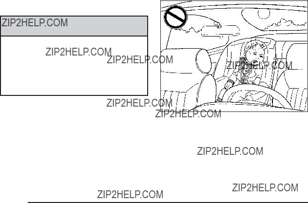
Windows
{ CAUTION:
Leaving children, helpless adults, or pets in a vehicle with the windows closed is dangerous. They can be overcome by the extreme heat and suffer permanent injuries or even death from heat stroke. Never leave a child, a helpless adult, or a pet alone in a vehicle, especially with the windows closed in warm or hot weather.
Power Windows
{ CAUTION:
Leaving children in a vehicle with the keys is dangerous for many reasons, children or others could be badly injured or even killed. They could operate the power windows or other controls or even make the vehicle move. The windows will function and they could be seriously injured or killed if caught in the path of a closing window. Do not leave keys in a vehicle with children.
When there are children in the rear seat use the window lockout button to prevent unintentional operation of the windows.
Driver???s Side Shown
The power window controls are located on each of the side doors. The driver???s door also has switches that control the passenger and rear windows.
Press the switch to lower the window. Pull up on the front edge of the switch to raise the window.
The power windows work when the ignition has been turned to ACC/ACCESSORY or ON/RUN or when Retained Accessory Power (RAP) is active. See
Retained Accessory Power (RAP) on page

The driver???s window switch has an
the switch. Press the switch part way, and the driver???s window will open a small amount. Press the switch down all the way, release it, and the window will go down automatically.
To stop the window while it is lowering, press and release the top of, or pull up on the switch.
Window Lockout
o (Window Lockout): Your vehicle has a lockout feature to prevent rear seat passengers from operating the windows. Press the lockout button, located with the power window switches, to turn the feature on and off. When the red band on the button is showing,
the lockout feature is off.
Sun Visors
To block out glare, swing down the visor(s). The sun visors can also be detached from the center mount and swung out to cover the side windows. They can also be slid along the rod to cover different areas of the front window.
Visor Vanity Mirrors
Your vehicle has visor vanity mirrors. Swing down the sun visor and lift the cover to expose the mirror.
Vehicle theft is big business, especially in some cities. This vehicle has

Content
Your vehicle may have a content
Arming the System
To arm the system:
1.Turn the ignition off.
2.Press lock on the RKE transmitter.
The system will arm after either of the following occur:
???30 seconds after all the doors are closed.
???60 seconds with any door open.
Press the lock button on the RKE transmitter a second time, while all the doors are closed, to immediately arm the system. The system still arms in 60 seconds if a door is open. When the open door is closed, it also arms.
The security light turns on to indicate that arming has been initiated. Once the system is armed, the security light ???ashes once every three seconds.
If the security light ???ashes twice per second, a door is open.
Locking the vehicle with the manual lock knobs on the doors will not arm the system.
Disarming the System
Disarm the system by doing any one of the following:
???Press the RKE transmitter unlock button.
???Turn the ignition on.
Once the system is disarmed, the security light stops ???ashing.

How the System Alarm is Activated
If the system is armed, it can be activated by either:
???Opening the driver???s door or tailgate. This causes a 10 second
???Opening any other door. This immediately causes a full alarm of horn and lights for 30 seconds.
When an alarm event has ???nished, the system
How to Turn Off the System Alarm
To turn off the system alarm, do one of the following:
???Press the lock button on the RKE transmitter. The system will then
???Press the unlock button on the RKE transmitter. This will also disarm the system.
???Insert the key in the ignition and turn it on. This will also disarm the system.
How to Detect a Tamper Condition
The content theft security system alarm was previously activated if three chirps sound when you press the lock or unlock buttons on the RKE transmitter.
Immobilizer
The
This device complies with Part 15 of the FCC Rules. Operation is subject to the following two conditions:
1.This device may not cause harmful interference.
2.This device must accept any interference received, including interference that may cause undesired operation.
This device complies with
1.This device may not cause interference.
2.This device must accept any interference received, including interference that may cause undesired operation of the device.
Changes or modi???cations to this system by other than an authorized service facility could void authorization to use this equipment.

Immobilizer Operation
Your vehicle has
The system is automatically armed when the key is removed from the ignition.
You do not have to manually arm or disarm the system.
The security light will come on if there is a problem with arming or disarming the
When the
When trying to start the vehicle if the engine does not start and the security light comes on, there may be a problem with your
If the engine still does not start, and the key appears to be undamaged, try another ignition key. At this time, you may also want to check the fuse, see Fuses and Circuit Breakers on page
It may be possible for the
lost or do not operate, you must see your dealer/retailer or a locksmith who can service
See your dealer/retailer or a locksmith who can service

To program the new key:
1.Verify that the new key has a 1 stamped on it.
2.Insert the already programmed key in the ignition and start the engine. If the engine will not start, see your dealer/retailer for service.
3.After the engine has started, turn the key to LOCK/OFF, and remove the key.
4.Insert the key to be programmed and turn it to the ON/RUN position within ???ve seconds of the original key being turned to the LOCK/OFF position.
The security light will turn off once the key has been programmed.
5.Repeat Steps 1 through 4 if additional keys are to be programmed.
If you are ever driving and the security light comes on and stays on, you may be able to restart your engine if you turn it off. Your
If you lose or damage your
Do not leave the key or device that disarms or deactivates the theft deterrent system in the vehicle.
Starting and Operating Your
Vehicle
New Vehicle
Notice: The vehicle does not need an elaborate
???Do not drive at any one constant speed, fast or slow, for the ???rst 500 miles (805 km). Do not make
???Avoid making hard stops for the ???rst 200 miles (322 km) or so. During this time the new brake linings are not yet broken in. Hard stops with new linings can mean premature wear and earlier replacement. Follow this
???Do not tow a trailer during
Following

Ignition Positions
The ignition switch has four different positions.
In order to shift out of P (Park), the ignition must be in ON/RUN or ACC/ACCESSORY and the brake pedal must be applied.
Notice: Using a tool to force the key to turn in the ignition could cause damage to the switch or break the key. Use the correct key, make sure it is all the way in, and turn it only with your hand. If the key cannot be turned by hand, see your dealer/retailer.
9 (LOCK/OFF): This position locks the steering column when the key is removed. The key can only be removed in LOCK/OFF.
On vehicles with an automatic transmission, the shift lever must be in P (Park) to turn the ignition switch to LOCK/OFF.
On vehicles with a manual transmission, the ignition switch can be turned to LOCK/OFF in any shift lever position.
The steering can bind with the wheel turned off center. If this happens, move it from right to left while turning the key to ACC/ACCESSORY. If this does not work, then the vehicle needs service.
{ CAUTION:
If you have a manual transmission removing the key from the ignition switch will lock the steering column and result in a loss of ability to steer the vehicle. This could cause a collision. If you need to turn the engine off while the vehicle is moving, turn the key to ACC/ACCESSORY.
ACC (ACC/ACCESSORY): This position operates some of the electrical accessories. It unlocks the steering wheel and ignition.

R (ON/RUN): This is the position in which you can operate the electrical accessories and to display some instrument panel cluster warning and indicator lights. The switch stays in this position when the engine is running.
If you leave the key in the ACC/ACCESSORY or ON/ RUN position with the engine off, the battery could be drained. You may not be able to start the vehicle if the battery is allowed to drain for an extended period of time.
/ (START): This position starts the engine. When the engine starts, release the key. The ignition switch will return to ON/RUN for driving.
A warning tone will sound when the driver door is opened, the ignition is in LOCK/OFF or ACC/ACCESSORY and the key is in the ignition.
Column Lock Release
For vehicles with an automatic transmission, the following procedure allows the ignition to be turned to LOCK/OFF and ignition key to be removed in case of a dead battery or low voltage battery.
1. Make sure the shift lever is in P (Park).
2.Remove the cover from the bottom of the steering column.

3.Locate the plunger.
4.Press and hold the plunger while turning the ignition key to LOCK/OFF. Remove the key.
Have the vehicle serviced at your dealer/retailer as soon as possible.
Retained Accessory Power (RAP)
These vehicle accessories may be used for up to 10 minutes after the engine is turned off.
???Audio System
???Power Windows
???Sunroof, if equipped
The power windows and sunroof will continue to work for up to 10 minutes or until any door is opened. The radio will work when the key is in ON/RUN or ACC/ ACCESSORY. Once the key is turned from ON/RUN to OFF/LOCK, the radio will continue to work for 10 minutes or until the driver door is opened.
Starting the Engine
Place the transmission in the proper gear.
Automatic Transmission
Move the shift lever to P (Park) or N (Neutral). The engine will not start in any other position. To restart the vehicle when it is already moving, use N (Neutral) only.
Notice: Do not try to shift to P (Park) if the vehicle is moving. If you do, you could damage the transmission. Shift to P (Park) only when the vehicle is stopped.

Manual Transmission
The shift lever should be in N (Neutral) and the parking brake engaged. Hold the clutch pedal down to the ???oor and start the engine. The vehicle will not start if the clutch pedal is not all the way down.
Starting Procedure
1.With your foot off the accelerator pedal, turn the ignition key to START. When the engine starts, let go of the key. The idle speed will go down as the engine warms. Do not race the engine immediately after starting it. Operate the engine and transmission gently to allow the oil to warm up and lubricate all moving parts.
The vehicle has a
Notice: Cranking the engine for long periods of time, by returning the key to the START position immediately after cranking has ended, can overheat and damage the cranking motor, and drain the battery. Wait at least 15 seconds between each try, to let the cranking motor cool down.
2.If the engine does not start after
Notice: The engine is designed to work with the electronics in the vehicle. If you add electrical parts or accessories, you could change the way the engine operates. Before adding electrical equipment, check with your dealer/retailer. If you do not, the engine might not perform properly. Any resulting damage would not be covered by the vehicle warranty.
Engine Coolant Heater
The engine coolant heater can provide easier starting and better fuel economy during engine
above 0??F (???18??C).
To Use the Engine Coolant Heater
1.Turn off the engine.
2.Open the hood and unwrap the electrical cord. The electrical cord is located on the passenger side of the vehicle near the headlamp and
the radiator.
3.Plug it into a normal, grounded
{ CAUTION:
Plugging the cord into an ungrounded outlet could cause an electrical shock. Also, the wrong kind of extension cord could overheat and cause a ???re.
You could be seriously injured. Plug the cord into a properly grounded
15amps.
4.Before starting the engine, be sure to unplug and store the cord as it was before to keep it away from moving engine parts, to prevent damage.
The length of time the heater should remain plugged in depends on several factors. Ask a dealer/retailer in the area where you will be parking the vehicle for the best advice on this.
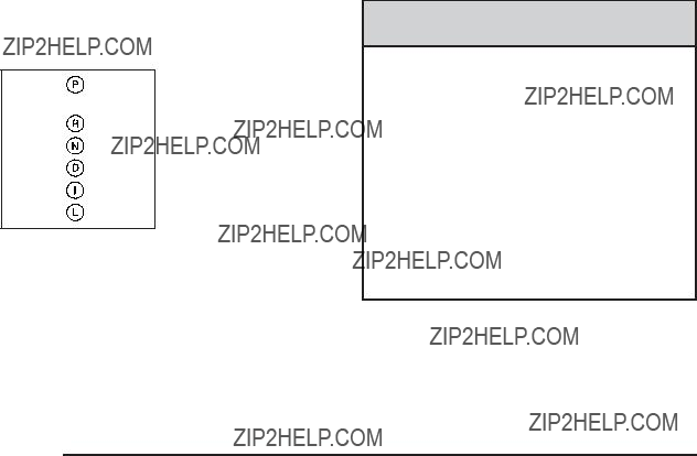
Automatic Transmission Operation
If the vehicle has an automatic transmission, the shift lever is located on the console between the seats.
There are several different positions for the automatic transmission.
P (Park): This position locks the front wheels. It is the best position to use when starting the engine because the vehicle cannot move easily.
{ CAUTION:
It is dangerous to get out of the vehicle if the shift lever is not fully in P (Park) with the parking brake ???rmly set. The vehicle can roll.
Do not leave the vehicle when the engine is running unless you have to. If you have left the engine running, the vehicle can move suddenly. You or others could be injured. To be sure the vehicle will not move, even when you are on fairly level ground, always set the parking brake and move the shift lever to P (Park). See Shifting
Into Park (Automatic Transmission) on page
Make sure the shift lever is fully in P (Park) before starting the engine. The vehicle has an automatic transmission shift lock control system. You have to fully apply the regular brakes ???rst and then press the shift lever button before the vehicle can shift from P (Park) when the ignition key is in ON/RUN.

If the vehicle cannot shift out of P (Park), ease pressure on the shift lever and push the shift lever all the way into P (Park) as you maintain brake application. Then press the shift lever button and then move the shift lever into another gear. See Shifting Out of Park (Automatic Transmission) on page
R (Reverse): Use this gear to back up.
Notice: Shifting to R (Reverse) while the vehicle is moving forward could damage the transmission. The repairs would not be covered by the vehicle warranty. Shift to R (Reverse) only after the vehicle is stopped.
To rock your vehicle back and forth to get out of snow, ice, or sand without damaging the transmission, see
If Your Vehicle is Stuck in Sand, Mud, Ice, or Snow on page
N (Neutral): In this position, the engine does not connect with the wheels. To restart the engine when the vehicle is already moving, use N (Neutral) only. Also, use N (Neutral) when the vehicle is being towed.
{ CAUTION:
Shifting into a drive gear while the engine is running at high speed is dangerous. Unless your foot is ???rmly on the brake pedal, the vehicle could move very rapidly. You could lose control and hit people or objects. Do not shift into a drive gear while the engine is running at high speed.
Notice: Shifting out of P (Park) or N (Neutral) with the engine running at high speed may damage
the transmission. The repairs would not be covered by the vehicle warranty. Be sure the engine is
not running at high speed when shifting the vehicle.
D (Drive): This position is for normal driving with the automatic transmission. It provides the best fuel economy. If you need more power for passing and you are:
???Going less than about 35 mph (55 km/h), push the accelerator pedal about halfway down.
???Going about 35 mph (55 km/h), push the accelerator all the way down.

Downshifting the transmission in slippery road conditions could result in skidding, see ???Skidding??? under Loss of Control on page
I (Intermediate): This position is also used for normal driving. However, it reduces vehicle speed without
using the brakes for slight downgrades where the vehicle would otherwise accelerate due to steepness of grade. If constant upshifting or downshifting occurs while driving up steep hills, this position can be used to prevent repetitive types of shifts. You might choose
I (Intermediate) instead of D (Drive) when driving on hilly, winding roads and when towing a trailer, so that there is less shifting between gears.
PERFORMANCE SHIFTING: If the vehicle has this feature, it can detect a change in driving patterns while in the Intermediate position. If you make an aggressive driving maneuver, the vehicle???s transmission automatically shifts to the lowest possible gear to maximize vehicle performance. The vehicle will automatically return to normal operation when you return to normal driving patterns.
L (Low): This position reduces vehicle speed more than I (Intermediate) without actually using the brakes. You can use it on very steep hills, or in deep snow or mud. If the shift lever is put in L (Low), the transmission will not shift into L (Low) until the vehicle is going slowly enough.
Notice: Spinning the tires or holding the vehicle in one place on a hill using only the accelerator pedal may damage the transmission. The repair will not be covered by the vehicle warranty. If you are stuck, do not spin the tires. When stopping on a hill, use the brakes to hold the vehicle in place.
Manual Transmission Operation
This is the shift pattern for standard models.

This is the shift pattern for SS models.
Here is how to operate the manual transmission:
1 (First): Press the clutch pedal and shift into 1 (First). Then, slowly let up on the clutch pedal as you press the accelerator pedal.
You can shift into 1 (First) when the vehicle is traveling less than 20 mph (32 km/h). If you have come to a complete stop and it is hard to shift into 1 (First), put the shift lever in N (Neutral) and let up on the clutch pedal. Press the clutch pedal back down. Then shift into
1 (First).
2 (Second): Press the clutch pedal as you let up on the accelerator pedal and shift into 2 (Second). Then, slowly let up on the clutch pedal as you press the accelerator pedal.
3 (Third), 4 (Fourth) and 5 (Fifth): Shift into 3 (Third), 4 (Fourth) and 5 (Fifth) the same way you do for
2 (Second). Slowly let up on the clutch pedal as you press the accelerator pedal down.
To stop, let up on the accelerator pedal and press the brake pedal. Just before the vehicle stops, press the clutch pedal and the brake pedal, and shift to N (Neutral).
N (Neutral): Use this position when you start or idle the engine.
R (Reverse): To back up, press down the clutch pedal and shift into R (Reverse).
For SS models, lift upwards on the ring located on the underside of the shift knob to shift into R (Reverse).
Notice: Shifting to R (Reverse) while the vehicle is moving forward could damage the transmission. The repairs would not be covered by the vehicle warranty. Shift to R (Reverse) only after the vehicle is stopped.
Also, use R (Reverse), along with the parking brake, for parking the vehicle.

Shift Speeds
{ CAUTION:
If you skip a gear when you downshift, you could lose control of the vehicle. You could injure yourself or others. Do not shift down more than one gear at a time when you downshift.
If the vehicle has a manual transmission, there may be an
When this light comes on, you can shift to the next higher gear if weather, road, and traffic conditions let you. For the best fuel economy, accelerate slowly and shift when the light comes on.
While accelerating, it is normal for the light to go on and off if you quickly change the position of the accelerator. Ignore the light when downshifting.
If the vehicle has the 2.0L turbo engine and manual transmission, it has the capability of
Electronic Stability Control (ESC) on page
To utilize this feature:
1.Accelerate the vehicle by fully depressing the accelerator pedal.
2.Just prior to reaching the maximum engine speed, quickly complete the upshift utilizing the clutch while keeping the accelerator pedal fully applied. A quicker shift maneuver gives the best performance. If the engine is operated at the maximum engine speed for greater than one second, the engine exits the

Parking Brake
The parking brake lever is located between the front seats.
{ CAUTION:
If the front passenger seat back is folded down, the armrest may make it awkward to grab and pull up the parking brake lever. If the lever is not
CAUTION: (Continued)
CAUTION: (Continued)
pulled up far enough, the vehicle may roll and you or others could be injured. Move your hand lower on the lever or raise the seat back so that you can set the brake.
To set the parking brake, hold the brake pedal down and pull up on the parking brake lever. If the ignition is on, the brake system warning light will come on.
See Brake System Warning Light on page
To release the parking brake, hold the brake pedal down. Pull the parking brake lever up until you can press the release button. Hold the release button in as you move the brake lever all the way down.
If you forget to release your parking brake, a chime will sound and a warning message will be displayed when the parking brake is applied and the vehicle
is moving faster than 5 mph (8 km/h). See DIC Warnings and Messages on page
Notice: Driving with the parking brake on can overheat the brake system and cause premature wear or damage to brake system parts. Make sure that the parking brake is fully released and the brake warning light is off before driving.

Shifting Into Park (Automatic
Transmission)
{ CAUTION:
It can be dangerous to get out of the vehicle if the shift lever is not fully in P (Park) with the parking brake ???rmly set. The vehicle can roll. If you have left the engine running, the vehicle can move suddenly. You or others could be injured. To be sure the vehicle will not move, even when you are on fairly level ground, use the steps that follow. If you are pulling a trailer, see Towing a Trailer (Automatic Transmission) on page
To shift into P (Park):
1.Hold the brake pedal down and set the parking brake. See Parking Brake on page
2.Move the shift lever into P (Park) by holding in the button on the shift lever and pushing the lever all the way toward the front of the vehicle.
3.Turn the ignition key to LOCK/OFF.
Leaving the Vehicle With the Engine
Running (Automatic Transmission)
{ CAUTION:
It can be dangerous to leave the vehicle with the engine running. The vehicle could move suddenly if the shift lever is not fully in P (Park) with the parking brake ???rmly set. And, if you leave the vehicle with the engine running, it could overheat and even catch ???re. You or others could be injured. Do not leave the vehicle with the engine running.
If you have to leave an automatic transmission vehicle with the engine running, be sure the vehicle is in
P (Park) and the parking brake is ???rmly set before you leave it. After you have moved the shift lever into
P (Park), hold the brake pedal down. Then, see if you can move the shift lever away from P (Park) without ???rst pushing the button. If you can, it means that the shift lever was not fully locked into P (Park).

Torque Lock (Automatic Transmission)
If you are parking on a hill and you do not shift into
P (Park) properly, the weight of the vehicle may put too much force on the parking pawl in the transmission. You may ???nd it difficult to pull the shift lever out of P (Park).
This is called ???torque lock.??? To prevent torque lock, set the parking brake and then shift into P (Park) properly before you leave the driver seat. To ???nd out how, see
Shifting Into Park (Automatic Transmission) on page
Move the shift lever out of P (Park) before you release the parking brake.
If torque lock does occur, you may need to have another vehicle push yours a little uphill to take some of the pressure from the parking pawl in the transmission, so you can pull the shift lever out of P (Park).
Shifting Out of Park
(Automatic Transmission)
This vehicle is equipped with an electronic shift lock release system. The shift lock release is designed to:
???Prevent ignition key removal unless the shift lever is in P (Park) with the shift lever button fully released, and
???Prevent movement of the shift lever out of
P (Park) unless the ignition is in ON/RUN or ACC/ ACCESSORY and the regular brake pedal is applied.
The shift lock release is always functional except in the case of a an uncharged or low voltage (less than 9 volt) battery.

If the vehicle has an uncharged battery or a battery with low voltage, try charging or jump starting the battery. See Jump Starting on page
To shift out of P (Park):
1.Apply the brake pedal.
2.Then press the shift lever button.
3.Move the shift lever to the desired position. If you still are unable to shift out of P (Park):
1.Fully release the shift lever button.
2.While holding down the brake pedal, press the shift lever button again.
3.Move the shift lever to the desired position.
If you still cannot move the shift lever from P (Park), consult your dealer/retailer or a professional towing service.
Parking the Vehicle
(Manual Transmission)
Before leaving the vehicle, fully press the clutch pedal down, move the shift lever into R (Reverse), and ???rmly apply the parking brake. Once the shift lever has been placed in R (Reverse) with the clutch pedal pressed down, the ignition key can be turned to LOCK/OFF, then remove the key and release the clutch pedal. See Manual Transmission Operation on page
Parking Over Things That Burn
{ CAUTION:
Things that can burn could touch hot exhaust parts under the vehicle and ignite. Do not park over papers, leaves, dry grass, or other things that can burn.
Engine Exhaust
{ CAUTION:
Engine exhaust contains Carbon Monoxide (CO) which cannot be seen or smelled. Exposure to CO can cause unconsciousness and even death.
Exhaust may enter the vehicle if:
???The vehicle idles in areas with poor ventilation (parking garages, tunnels, deep snow that may block underbody air???ow or tail pipes).
???The exhaust smells or sounds strange or different.
???The exhaust system leaks due to corrosion or damage.
CAUTION: (Continued)
CAUTION: (Continued)
???The vehicle???s exhaust system has been modi???ed, damaged or improperly repaired.
???There are holes or openings in the vehicle body from damage or
If unusual fumes are detected or if it is suspected that exhaust is coming into the vehicle:
???Drive it only with the windows completely down.
???Have the vehicle repaired immediately.
Never park the vehicle with the engine running in an enclosed area such as a garage or a building that has no fresh air ventilation.
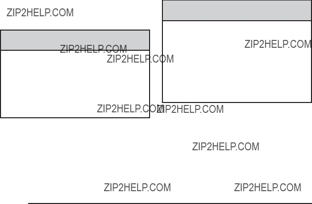
Running the Vehicle While Parked
It is better not to park with the engine running. But if you ever have to, here are some things to know.
{ CAUTION:
Idling a vehicle in an enclosed area with poor ventilation is dangerous. Engine exhaust may enter the vehicle. Engine exhaust contains Carbon Monoxide (CO) which cannot be seen or smelled. It can cause unconsciousness and even death. Never run the engine in an enclosed area that has no fresh air ventilation. For more information, see
Engine Exhaust on page
{ CAUTION:
It can be dangerous to get out of the vehicle
if the automatic transmission shift lever is not fully in P (Park) with the parking brake ???rmly set.
The vehicle can roll. Do not leave the vehicle when the engine is running unless you have to.
If you have left the engine running, the vehicle can move suddenly. You or others could be injured. To be sure the vehicle will not move, even when you are on fairly level ground, always set the parking brake and move the shift lever to P (Park).
Follow the proper steps to be sure the vehicle will not move. See Shifting Into Park (Automatic Transmission) on page
If parking on a hill and pulling a trailer, see Towing a Trailer (Automatic Transmission) on page

Mirrors
Manual Rearview Mirror
Hold the inside rearview mirror in the center to move it for a clearer view behind your vehicle. Adjust the mirror to avoid glare from the headlamps behind you. Push the tab forward for daytime use and pull it for nighttime use.
If the vehicle has map lamps, press the buttons located at the bottom of the mirror to turn them on or off.
Automatic Dimming Rearview Mirror
The vehicle may have an automatic dimming inside rearview mirror with a compass and map lights and/or OnStar??.
Vehicles with OnStar have three additional control buttons located at the bottom of the mirror. See your dealer/retailer for more information on the system
and how to subscribe to OnStar??. See OnStar?? System on page
Press the buttons located at the bottom of the mirror to turn the map lights on or off.
O (On/Off): Press to turn the dimming feature on or off.
Your vehicle may also have a Rear Vision Camera. See Rear Vision Camera (RVC) on page
Automatic Dimming Mirror Operation
Automatic dimming reduces the glare of lights from behind the vehicle. The dimming feature comes on and the indicator light illuminates each time the vehicle is started.
Cleaning the Mirror
Do not spray glass cleaner directly on the mirror. Use a soft towel dampened with water.
Compass
Compass Operation
Y / O (On/Off): If the vehicle has one of these buttons, press to turn the compass on or off.
With the compass feature on, each time the vehicle is started, the compass displays the current compass direction after a few seconds.

Compass Calibration
If after a few seconds the display does not show a compass direction, (N for North for example), there may be a strong magnetic ???eld interfering with the compass. Interference can be caused by a magnetic antenna mount, note pad holder, or similar object. If CAL appears in the compass window, the compass may need to be reset or calibrated.
To calibrate the compass:
1.Make sure CAL is displayed. If CAL is not displayed, press and hold the compass button until CAL displays.
2.While CAL displays, drive the vehicle in circles at 5 mph (8 km/h) or less until the display reads a direction.
Compass Variance
The mirror is set to zone eight. If you do not live in zone eight or drive out of the area, the compass variance needs to be changed to the appropriate zone.
To adjust for compass variance:
1.Find the current location and variance zone number on the following zone map.
2.Press and hold the compass button until a Z and a zone number displays.
3.Once the zone number displays, press the compass button repeatedly until the correct zone number is reached. If CAL displays in the compass window, the compass may need calibration. See ???Compass Calibration??? listed previously.

Outside Power Mirrors
Controls for the outside power mirrors are located on the driver door armrest.
1.Press the left or right side of the selector switch located beneath the control pad, to select the driver or passenger mirror.
2.Press one of the four buttons located on the control pad to move the mirror to the desired direction.
3.Adjust each outside mirror so that a little of the vehicle and the area behind it can be seen.
Keep the selector switch in the center position when not adjusting either outside mirror.
Manually fold the mirrors inward to prevent damage when going through an automatic car wash. To fold, push the mirror toward the vehicle. Push the mirror outward, to return to its original position.
Blind Spot Mirrors
The blind spot mirror is a small convex mirror built into the upper and outer corner of both outside mirrors.
It is designed to increase driver visibility and show objects that may be in the vehicle???s blind zone.
Driving with the Blind Spot Mirror
The illustration represents how a vehicle appears in the blind spot mirror when a vehicle is approaching the blind zone.

1.When the approaching vehicle is a long distance away, the image in the main mirror is small and near the inboard edge of the mirror.
2.As the vehicle gets closer, the image in the main mirror gets larger and moves outboard.
3.As the vehicle enters the blind zone, the image transitions from the main mirror to the blind spot mirror.
4.When the vehicle is completely in the blind zone, the image will only appear in the blind spot mirror and is entirely off the main mirror.

Using the Outside Mirror with the Blind Spot Mirror
1.Set the main mirror so that your vehicle can just be seen and your blind spot mirror has a clear unobstructed view.
2.When checking for traffic or before changing a lane, look at the main driver/passenger side mirror to observe traffic in the adjacent lane, behind your vehicle. Check the blind spot mirror for a vehicle
in the blind zone. Then, glance over your shoulder to double check before moving slowly into the adjacent lane.
Outside Convex Mirror
{ CAUTION:
A convex mirror can make things (like other vehicles) look farther away than they really are. If you cut too sharply into the right lane, you could hit a vehicle on the right. Check the inside mirror or glance over your shoulder before changing lanes.
The passenger side mirror is convex shaped. A convex mirror???s surface is curved so more can be seen from the driver seat.

Object Detection Systems
Rear Vision Camera (RVC)
The vehicle may have a Rear Vision Camera system. Read this entire section before using it.
{ CAUTION:
The Rear Vision Camera (RVC) system does not replace driver vision. RVC does not:
???Detect objects that are outside the camera???s ???eld of view, below the bumper, or underneath the vehicle.
???Detect children, pedestrians, bicyclists, or pets.
Do not back the vehicle by only looking at the rear vision camera screen, or use the screen during longer, higher speed backing maneuvers or where there could be
CAUTION: (Continued)
CAUTION: (Continued)
So if you do not use proper care before backing up, you could hit a vehicle, child, pedestrian, bicyclist, or pet, resulting in vehicle damage, injury, or death. Even though the vehicle has the RVC system, always check carefully before backing up by checking behind and around the vehicle.
The rear vision camera system is designed to help the driver when backing up by displaying a view of the area behind the vehicle. When the key is in the ON/RUN position and the driver shifts the vehicle into R (Reverse), the video image automatically appears on the inside rear view mirror. Once the driver shifts out of R (Reverse), the video image automatically disappears from the inside rear view mirror.

Turning the Rear Vision Camera System Off or On
To turn off the rear vision camera system, press and hold z , located on the inside rearview mirror, until the left indicator light turns off. The rear vision camera display is now disabled.
To turn the rear vision camera system on again, press and hold z until the left indicator light illuminates. The rear vision camera system display is now enabled and the display will appear in the mirror normally.
Rear Vision Camera Location
The camera is located in the rear of the vehicle.
The area displayed by the camera is limited and does not display objects that are close to either corner or under the bumper. The area displayed can vary depending on vehicle orientation or road conditions. The distance of the image that appears on the screen differs from the actual distance.
The following illustration shows the ???eld of view that the camera provides.

When the System Does Not Seem To
Work Properly
The rear vision camera system might not work properly or display a clear image if:
??? The RVC is turned off. See ???Turning the Rear Camera System On or Off??? earlier in this section.
???
??? The sun or the beam of headlights is shining directly into the camera lens.
??? Ice, snow, mud, or anything else builds up on the camera lens. Clean the lens, rinse it with water, and wipe it with a soft cloth.
??? The back of the vehicle is in an accident, the position and mounting angle of the camera can change or the camera can be affected.
Be sure to have the camera and its position and mounting angle checked at your dealer/retailer.
??? There are extreme temperature changes.
A.View displayed by the camera.
B.Corner of the rear bumper.
The rear vision camera system display in the rearview mirror may turn off or not appear as expected due to one of the following conditions. If this occurs the left indicator light on the mirror will ???ash.
???A slow ???ash may indicate a loss of video signal, or no video signal present during the reverse cycle.
???A fast ???ash may indicate that the display has been on for the maximum allowable time during a reverse cycle, or the display has reached an Over Temperature limit.
The fast ???ash conditions are used to protect the video device from high temperature conditions. Once conditions return to normal the device will reset and the green indicator will stop ???ashing.
During any of these fault conditions, the display will be blank and the indicator will continue to ???ash as long as the vehicle is in R (Reverse) or until the conditions return to normal.
Pressing and holding z when the left indicator light is ???ashing will turn off the video display along with the left indicator light.
OnStar?? System
OnStar uses several innovative technologies and live advisors to provide a wide range of safety, security, information, and convenience services. If the airbags deploy, the system is designed to make an automatic call to OnStar Emergency advisors who can request emergency services be sent to your location. If the keys are locked in the vehicle, call OnStar at
for 60 days, is available on most vehicles. OnStar
OnStar service is provided subject to the OnStar Terms and Conditions included in the OnStar Subscriber glove box literature.

Some services such as Remote Door Unlock or Stolen Vehicle Location Assistance may not be available until the owner of the vehicle registers with OnStar. After the ???rst prepaid year, contact OnStar to select a monthly or annual subscription payment plan. If a payment plan is not selected, the OnStar system and all services, including airbag noti???cation and emergency services, may be deactivated and no longer available. For more
information visit onstar.com (U.S.) or onstar.ca (Canada), or press the OnStar button to speak with an advisor.
Not all OnStar services are available on all vehicles. To check if this vehicle is able to provide the services described below, or for a full description of OnStar services and system limitations, see the OnStar Owner???s Guide in the glove box or visit onstar.com (U.S.) or onstar.ca (Canada), contact OnStar at
OnStar Services Available with the Safe & Sound Plan
???Automatic Noti???cation of Airbag Deployment
???Advanced Automatic Crash Noti???cation (AACN) (If equipped)
???Link to Emergency Services
???Roadside Assistance
???Stolen Vehicle Location Assistance
???Remote Door Unlock/Vehicle Alert
???OnStar Vehicle Diagnostic Email
???GM Goodwrench On Demand Diagnostics
???OnStar
???OnStar Virtual Advisor (U.S. Only)
OnStar Services Included with Directions & Connections Plan
???All Safe and Sound Plan Services
???OnStar
???RideAssist
???Information and Convenience Services

OnStar
OnStar
OnStar
Vehicles with the OnStar
OnStar Virtual Advisor
OnStar Virtual Advisor is a feature of OnStar
OnStar Steering Wheel Controls
This vehicle may have a Talk/Mute button that can be used to interact with OnStar
See Audio Steering Wheel Controls on page
On some vehicles, the mute button can be used to dial numbers into voice mail systems, or to dial phone extensions. See the OnStar Owner???s Guide for more information.

How OnStar Service Works
The OnStar system can record and transmit vehicle information. This information is automatically sent to an OnStar Call Center when the OnStar button is pressed, the emergency button is pressed, or if the airbags or AACN system deploy. This information usually includes the vehicle???s GPS location and, in the event of a crash, additional information regarding the crash that the vehicle was involved in (e.g. the direction from which the vehicle was hit). When the Virtual Advisor feature of OnStar
OnStar service cannot work unless the vehicle is in a place where OnStar has an agreement with a wireless service provider for service in that area. OnStar service also cannot work unless the vehicle is in a place where the wireless service provider OnStar has hired for that area has coverage, network capacity and reception when the service is needed, and technology that is compatible with the OnStar service. Not all services are available everywhere, particularly in remote or enclosed areas,
or at all times.
Location information about the vehicle is only available if the GPS satellite signals are unobstructed and available.
The vehicle must have a working electrical system, including adequate battery power, for the OnStar equipment to operate. There are other problems OnStar cannot control that may prevent OnStar from providing OnStar service at any particular time or place. Some examples are damage to important parts of the vehicle in a crash, hills, tall buildings, tunnels, weather or wireless phone network congestion.
Your Responsibility
Increase the volume of the radio if the OnStar advisor cannot be heard. If the light next to the OnStar buttons is red, the system may not be functioning properly.
Press the OnStar button and request a vehicle diagnostic. If the light appears clear (no light is appearing), your OnStar subscription has expired and all services have been deactivated. Press the OnStar button to con???rm that the OnStar equipment is active.

Storage Areas
Glove Box
Lift up on the glove box lever to open it.
Cupholders
There are two cupholders located in the ???oor console between the front seats. There is also a cupholder for the rear seat passenger located at the rear of the ???oor console.
If your vehicle is an SS model, the automatic transmission vehicles have a cupholder in front of the shift lever.
Cupholders have inserts that can be removed for cleaning.
Instrument Panel Storage
Your vehicle has a storage compartment on the instrument panel above the air vents. Push the button on the compartment to open the cover.
Floor Console Storage Area
There are two small storage compartments on the ???oor console.
Rear Storage Area
Your vehicle may have two rear storage areas that can be used for small items.

Rear Compartment Storage
Panel/Cover
Your vehicle may have an adjustable panel/cargo cover feature. The panel/cargo cover can be adjusted into four positions.
To use the panel in the ???rst position:
1.Insert the front corners of the panel into the lower guides.
2.Slide the panel forward.
3.Press down on the back of the panel to lock it in place.
The panel can be used in this position if you need additional space above the panel. Place the cargo on top of the panel in this position.
{ CAUTION:
If you were to carry things on the adjustable panel when it is in the upper (cargo cover) or center positions, during a sudden vehicle movement or a crash, those things could be thrown around in the vehicle. You or others could be injured. When it is in the upper or center position, always secure any cargo on the ???oor beneath the panel/cover.

To use the panel in the second position:
1.Insert the front corners of the panel into the top guides.
2.Slide the panel forward.
3.Press down on the back of the panel to lock it in place.
The third position is with the front corners placed in the lower guides and the rear corners placed in the upper guides. Do not load cargo on the panel in this position.
The fourth position is with the front corners placed in the lower guides closest to the rear seat for sub???oor access. Do not drive while the panel is in this position.
The panel can be used as a cargo cover for the
rear area. It has hooks underneath for shopping bags.
Your vehicle may have a cargo mat that covers the panel/cargo cover.

Roof Rack System
Your vehicle may be equipped with a roof rack system.
{ CAUTION:
If something is carried on top of the vehicle that is longer or wider than the luggage carrier ??? like paneling, plywood, or a mattress ??? the wind can catch it while the vehicle is being driven. This can cause a driver to lose control. The item being carried could be violently torn off, and this could cause a collision, and damage the vehicle. Items may be carried inside. Never carry something longer or wider than the luggage carrier on top of the vehicle.
Notice: Loading cargo on the luggage carrier that weighs more than 150 lbs (68 kg) or hangs over the rear sides of the vehicle may damage your vehicle. Load cargo so that it rests on the slats as far forward as possible and against the side rails making sure to fasten it securely.
Notice: Loading cargo directly on the roof of the vehicle may cause damage to the vehicle and would not be covered under warranty. Do not place
cargo on the roof the vehicle.
Do not exceed the maximum vehicle capacity when loading your vehicle. For more information on vehicle capacity and loading, see Loading the Vehicle on page
To prevent damage or loss of cargo as you are driving, check frequently to ensure your cargo is securely fastened.
The roof rack system has siderails that are attached to the roof. All cargo must be loaded on the luggage carrier crossrails only.
Use GM accessory racks that are compatible with your roof rack system, these are available at your GM dealer.
Convenience Net
Your vehicle may have a convenience net. The metal rings in the cargo area can be used to attach the convenience net for several uses. The net can be used to attach items secured to the ???oor, to the rear liftgate or liftgate glass. The net is not for larger, heavier loads.

Hideaway Rear Storage Bins
Your vehicle may have two storage bins located in the rear of the vehicle. Pull up on the handles to open and lift the lid. Use the key to lock/unlock the bins.
There is a rod that hooks into place to prop open the lid. Push the rod towards the lid to unhook it and lower the lid.
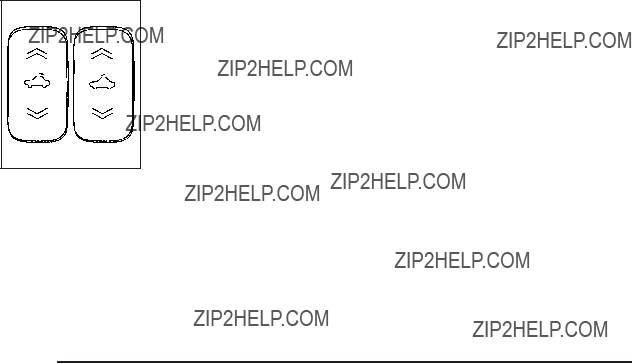
Sunroof
The vehicle may have a power sunroof.
The switches that operate the sunroof are located in the headliner.
To open or close the sunroof, the ignition must be in ON/RUN, ACC/ACCESSORY, or Retained Accessory Power (RAP) must be active. See Retained Accessory Power (RAP) on page
Express Open: To express open the power sunroof, fully press the driver???s side switch rearward once. To stop the sunroof glass in a desired position other than to the
Vent Open: To open to the vent position from the closed position, press and hold the passenger???s side sunroof switch forward. The rear of the sunroof panel will tilt upward to the full vent position. The sunshade must be opened manually.
Express Close: To express close the power sunroof, fully press the driver???s side switch forward once. To stop the sunroof glass in a desired position other than closed, press the switch again in either direction. The sunshade must be closed manually.
Close: To close the power sunroof, operate the controls according to one of the following:
???From the open position, press and hold the driver???s side sunroof switch forward. The sunshade must be closed manually.
???From the vent position, press and hold the passenger???s side sunroof switch rearward.
Section 3 Instrument Panel


??? NOTES

Instrument Panel Overview

The main components of the instrument panel are the following:
A.Outlet Adjustment on page
B.Cruise Control on page
C.Turn Signal/Multifunction Lever on page
D.Instrument Panel Cluster on page
E.Windshield Wipers on page
F.Instrument Panel Storage on page
G.Traction Control System (TCS) on page
(If Equipped). Electronic Stability Control (ESC). See Electronic Stability Control (ESC) on page
H.Passenger Airbag Status Indicator on page
I.Rear Side Cargo Door (HHR Panel Only) on page
J.Hood Release on page
K.Driver Information Center (DIC) on page
L.Horn on page
M.Audio Steering Wheel Controls on page
(If Equipped).
N.Instrument Panel Brightness on page
O.Audio System(s) on page
P.Climate Control System on page
Q.Rear Window Wiper/Washer on page
R.Shift Lever (Manual Shown). See Manual Transmission Operation on page
S.Accessory Power Outlet(s) on page
(If Equipped) and Cigarette Lighter (If Equipped). See Ashtray(s) and Cigarette Lighter on page
T.Fog Lamps on page
U.Hazard Warning Flashers on page
V.Glove Box on page

Hazard Warning Flashers
| (Hazard Warning Flasher): Press this button located on the instrument panel, to make the front and rear turn signal lamps ???ash on and off. This warns others that you are having trouble.
Press | again to turn the ???ashers off.
Horn
To sound the horn, press the horn symbols located on the steering wheel.
Tilt Wheel
A tilt wheel lets the steering wheel be adjusted before driving.
The tilt lever is located on the left side of the steering column.
To tilt the wheel, pull the lever down. Then, move the wheel to a comfortable position and raise the lever to lock the wheel in place.
Do not adjust the steering wheel while driving.

The lever on the left side of the steering column includes the following:
G : Turn and
5 3: Headlamp
O : Exterior Lamp Control
Information for these features is on the pages following.
An arrow on the instrument panel cluster ???ashes in the direction of the turn or lane change.
Move the lever all the way up or down to signal a turn.
Raise or lower the lever until the arrow starts to ???ash to signal a lane change. Hold it there until the lane change is complete.
The lever returns to its starting position when it is released.
If after signaling a turn or a lane change the arrows ???ash rapidly or does not come on, a signal bulb may be burned out.
Have the bulbs replaced. If the bulb is not burned out, check the fuse. See Fuses and Circuit Breakers on page
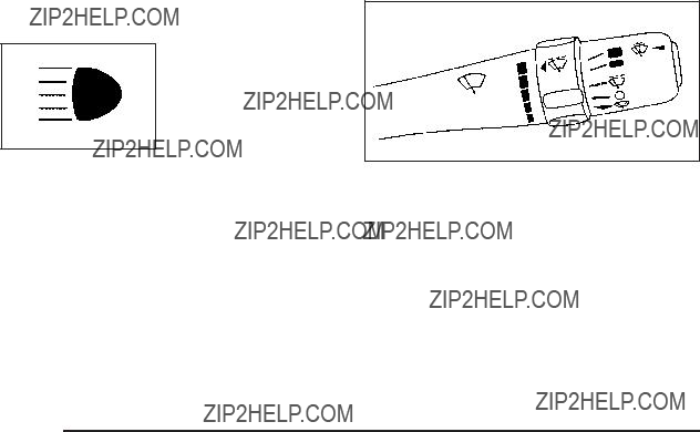
Headlamp
To change the headlamps from low beam to high beam, push the turn signal lever away from you.
This indicator light appears on the instrument panel cluster when the high beams are on.
To change the headlamps from high beam to low beam, pull the turn signal lever toward you.
This feature lets you use your
To use it, pull the turn signal/multifunction lever toward you until the
Windshield Wipers
The windshield wiper lever is located on the right side of the steering wheel.
Move the lever to one of the following positions:
1 (High Speed): For steady wiping at high speed.
6 (Low Speed): For steady wiping at low speed.
& (Delay): Use to set a delay between wipes.

6 (Delay/Intermittent Speed Sensitive): When the lever is in the delay position, move the intermittent adjust band to set for shorter or longer delay cycles. To the left of the adjust band are bars that indicate the frequency of the wipes. Smaller bars mean the wiper movement is less frequent. Larger bars mean the wiper movement is more frequent.
During intermittent wiping mode, the delay cycle time is sensitive to vehicle speed. As the vehicle speed increases the delay cycle time will decrease and wiper movement occurs more frequently.
9 (Off): Turns off the windshield wipers.
8 (Mist): Move the lever to mist, for a single wiping cycle and then release it. The windshield wipers will stop after one wipe and the lever returns to its original position. Hold the band on mist longer for continuous wipes.
As an added safety feature, if the wipers are on for more than 15 seconds, the vehicle???s headlamps will turn on automatically. They will turn off 15 seconds after
the wipers are turned off.
Clear snow and ice from the wiper blades before using them. If the blades are frozen to the windshield, gently loosen or thaw them. If they become damaged, install new blades or blade inserts. See Windshield Wiper Blade Replacement on page
Heavy snow or ice can overload the wiper motor.
A circuit breaker will stop the motor until it cools down.
Windshield Washer
To wash the windshield, press the button at the end of the lever until the washers begin.
{ CAUTION:
In freezing weather, do not use your washer until the windshield is warmed. Otherwise the washer ???uid can form ice on the windshield, blocking your vision.
When the button is released, the washers will stop, but the wipers will continue to wipe for about three times or will resume the speed being used before.

Rear Window Wiper/Washer
The rear window washer/wiper button is located on the instrument panel below the climate controls.
{ CAUTION:
In freezing weather, do not use your washer until the windshield is warmed. Otherwise the washer ???uid can form ice on the windshield, blocking your vision.
5 (Delay): Press to turn on the intermittent wiping setting that has a longer delay.
Y (Washer Fluid): Press to wash and wipe the window.
The rear window washer uses the same ???uid bottle as the windshield washer. However, the rear window washer will run out of ???uid before the windshield washer. If the windshield can be washed, but not the rear windows, check the ???uid level.
Z (Rear Wiper): Press to turn on an intermittent setting that has a shorter delay.
To turn either of the intermittent wiper settings off, press the opposite side of the button to turn it to the off position. Pressing the button all the way down on either side will activate an intermittent wiper setting.
Cruise Control
With cruise control, a speed of about 25 mph (40 km/h) or more can be maintained without keeping your foot on the accelerator. Cruise control does not work at speeds below 25 mph (40 km/h).
The brake must be applied at least one time, after the vehicle has been started, before cruise control will function.
{ CAUTION:
Cruise control can be dangerous where you cannot drive safely at a steady speed. So, do not use the cruise control on winding roads or in heavy traffic.
Cruise control can be dangerous on slippery roads. On such roads, fast changes in tire traction can cause excessive wheel slip, and you could lose control. Do not use cruise control on slippery roads.
Setting Cruise Control
{ CAUTION:
If you leave your cruise control on when you are not using cruise, you might hit a button and go into cruise when you do not want to. You could be startled and even lose control. Keep the cruise control switch off until you want to use cruise control.
The cruise control buttons are located on the left side of the steering wheel.
J (On/Off): Press to turn the cruise control system on and off. The indicator light on the button comes on when the cruise control is on and goes off when
the cruise control is turned off.
RES+ (Resume): Press to resume a set speed and to accelerate the speed.

SET??? (Set): Press to set a speed and to decrease the speed.
To set a speed do the following:
1.Press I to turn cruise control on. The indicator light on the button will come on.
2.Get to the desired speed.
3.Press the SET??? control button and release it. The CRUISE ENGAGED message will appear on the Driver Information Center (DIC) to show the system is engaged.
4.Take your foot off the accelerator pedal.
When you apply the brakes or operate the clutch pedal, the cruise control will shut off.
If the vehicle is in cruise control and the Traction Control System (TCS) begins to limit wheel spin, the cruise control will automatically disengage. See Traction Control System (TCS) on page
Resuming a Set Speed
Suppose the cruise control is set at a desired speed and then the brake is applied. This disengages the cruise control. To return to the previously set speed, you do not need to go through the set process again. Once the vehicle is going about 25 mph (40 km/h) or more, press the RES+ part of the button brie???y.
The vehicle goes back to the previously set speed.
Increasing Speed While Using Cruise
Control
There are two ways to go to a higher speed.
1.Disengage the cruise control by applying the brake pedal, but do not turn it off. Accelerate to a higher speed and reset the cruise control.
2.If the cruise control system is already engaged, press the RES+ button. Hold it there until the desired speed is reached, and then release the button. To increase the vehicle speed in small amounts, press the RES+ button brie???y and then release it. Each time this is done, the vehicle goes about 1 mph (1.6 km/h) faster.

Reducing Speed While Using Cruise
Control
If the cruise control system is already engaged,
???Push and hold the SET??? button until the lower speed desired is reached, then release it.
???To slow down in small amounts, push the SET??? button brie???y. Each time this is done, the vehicle goes about 1 mph (1.6 km/h) slower.
Passing Another Vehicle While Using
Cruise Control
Use the accelerator pedal to increase the vehicle speed. When you take your foot off the pedal, the vehicle slows down to the cruise control speed you set earlier.
Using Cruise Control on Hills
How well the cruise control will work on hills depends upon the vehicle speed, load and the steepness of the hills. When going up steep hills, you might have to step on the accelerator pedal to maintain the vehicle speed.
When going downhill, you might have to brake or shift to a lower gear to keep the vehicle speed down. When the brakes are applied the cruise control turns off.
Ending Cruise Control
To end cruise control, step lightly on the brake pedal or the clutch pedal if the vehicle has a manual transmission.
Stepping on the brake pedal or clutch pedal will only end the current cruise control session.
Press I to turn the system completely off.
Erasing Speed Memory
The cruise control set speed memory is erased when the cruise control or the ignition is turned off.
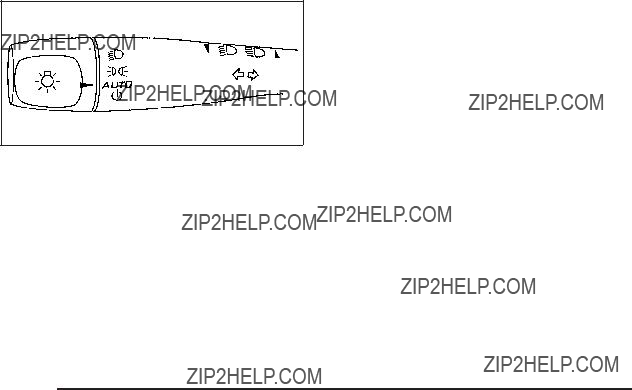
Headlamps
The lever on the left side of the steering column operates the exterior lamps.
The exterior lamp switch has the following four positions:
2 (Headlamps): Turns on the headlamps, parking lamps, and taillamps.
; (Parking Lamps): Turns on the parking lamps and taillamps only.
AUTO (Automatic Headlamp System): Automatically turns on the Daytime Running Lamps during daytime, and the headlamps, parking lamps, and taillamps at night.
P (Off/On): This position is the momentary Off/On switch for the Automatic Headlamp System. In Canada, this only works when the vehicles with an automatic transmission are in P (Park) and vehicles with a manual transmission have the parking brake set and the vehicle is not moving.
When operating in AUTO, a momentary turn of the switch to off/on will turn off the Automatic Headlamp System. An AUTO LIGHTS OFF message displays on the Driver Information Center (DIC) and a chime will sound. Turning the switch to off/on again will turn the Automatic Headlamp System back on. An AUTO LIGHTS ON message displays on the DIC. The Automatic Headlamp System is always turned on at the beginning of an ignition cycle for vehicles with manual transmission.

Wiper Activated Headlamps
The headlamps and parking lamps are activated
15 seconds after the windshield wipers are turned on. For this feature to work, automatic lighting must be enabled. See Headlamps on page
When the ignition is turned off, the
Headlamps on Reminder
If the drivers door is opened with the ignition off and the lamps on, a warning chime will sound. This indicates that the headlamps are still on.
Daytime Running Lamps (DRL)
Daytime Running Lamps (DRL) can make it easier for others to see the front of your vehicle during the day. Fully functional daytime running lamps are required on all vehicles ???rst sold in Canada.
The vehicle has a light sensor on top of the instrument panel. Do not cover this sensor or the headlamps
will come on when they are not needed.
The DRL system will make the headlamps come on at reduced brightness when the following conditions are met:
???The ignition is on.
???The exterior lamp control is turned to AUTO.
???The light sensor detects daytime light.
???The shift lever is not in P (Park).
While the DRL system is on, the taillamps, sidemarker lamps, and instrument panel lights will not be on.
For vehicles with an Automatic Transmission, the DRL system is off any time the vehicle is in P (Park). For vehicles with a Manual Transmission, the DRL system will be off when the vehicle is ???rst started, the park brake is applied, and the vehicle has not moved. The DRL system on U.S. vehicles can also be turned off by using the off/on switch for one ignition cycle.
The regular headlamp system should be turned on when needed.

Automatic Headlamp System
When it is dark enough outside, the automatic system turns on the headlamps at the normal brightness along with other lamps such as the taillamps, sidemarker, parking lamps, instrument panel lights, and interior switch backlighting.
Do not cover the light sensor, located on top of the instrument panel. If the sensor is covered the headlamps may remain on when they are not needed.
If the vehicle is driven through a parking garage, overcast weather or a tunnel, the automatic headlamp system may turn on.
There is a delay in the transition between the daytime and nighttime operation of the automatic lamp control system so that driving under bridges or bright overhead street lights does not affect the system. The automatic lamp control system will only be affected when the light sensor sees a change in lighting lasting longer than this delay.
If the vehicle is started in a dark garage, the automatic lamp system turns on immediately. Once the vehicle exits the garage, it will take about 20 seconds for the automatic lamp system to change to DRL if it is light outside. During that delay, the instrument panel cluster may not be as bright as usual. Make sure the instrument panel brightness control is in the full bright position. See Instrument Panel Brightness on page
To idle the vehicle with the system off, turn the ignition on and turn the exterior light switch to the off/on position. For vehicles ???rst sold in Canada, the transmission must stay in P (Park) for this function or the parking brake must be set for vehicles with manual transmissions.
Turn on the regular headlamps when they are needed.
Fog Lamps
For vehicles with fog lamps, the button is located on the instrument panel, to the right of the steering wheel.
The ignition must be on to use the fog lamps.
# : Press to turn the fog lamps on and off. An indicator light on the button comes on when the fog lamps are on.
The parking lamps automatically turn on and off when the fog lamps are turned on and off.
The fog lamps will turn off while the
Some localities have laws that require the headlamps to be on along with the fog lamps.

Instrument Panel Brightness
The control for this feature is located to the right of the steering wheel
and above the radio.
Move the thumbwheel to the left to dim the lights or to the right to brighten the lights.
The dome lamps will turn on when the thumbwheel is moved completely to the right.
Dome Lamp
Move the lever to the following positions:
9 (Off): Turns the lamp off, even when a door is opened.
1 (Door): Turns the lamp on whenever a door is opened.
The dome lamp and mirror reading lamps will turn on if the lever is in the door position and the instrument panel brightness control is turned to the brightest setting. See Instrument Panel Brightness on page
+ (On): Turns on the dome lamp.
Entry/Exit Lighting
The lamps inside the vehicle turn on when any door is opened. These lamps will fade out after about
20 seconds after all of the doors have been closed or when the ignition is turned to ON/RUN. These lamps will also turn on when pressing the unlock symbol button or the horn symbol on the keyless entry system transmitter.
The lamps inside the vehicle will stay on for about
20 seconds after the key is removed from the ignition to provide an illuminated exit.
Mirror Reading Lamps
The vehicle may have reading lamps on the rearview mirror. Push the button to turn the reading lamps on and off. The reading lamps will automatically come on when a door is open.
Rear Reading Lamps
Push the lens to turn the reading lamps on and off.

Electric Power Management
This vehicle has Electric Power Management (EPM), an advanced control system. It estimates the battery???s temperature and state of charge and then adjusts the voltage for best performance and extended life of the battery.
When the battery???s state of charge is low, the voltage is raised slightly to quickly put the charge back in. When the state of charge is high, the voltage is lowered slightly to prevent overcharging. If the vehicle has a voltmeter gage or voltage display on the Driver Information Center (DIC), you may see the voltage move up or down. This is normal. If there is a problem, an alert will be displayed.
The battery can be discharged at idle if the electrical loads are very high. This is true for all vehicles. This is because the generator (alternator) may not be spinning fast enough at idle to produce all the power that is needed for very high electrical loads.
A high electrical load occurs when several of the following loads are on: headlamps, high beams, fog lamps, rear window defogger, climate control fan at high speed, heated seats, engine cooling fans, trailer loads, and loads plugged into accessory power outlets.
EPM works to prevent excessive discharge of the battery. It does this by balancing the generator???s output and the vehicle???s electrical needs. It can increase engine idle speed to generate more power, whenever needed. It can temporarily reduce the power demands of some accessories.
Normally, these actions occur in steps or levels, without being noticeable. In rare cases at the highest levels
of corrective action, this action may be noticeable to the driver.
Battery
The vehicle has a battery saver feature designed to protect the vehicle???s battery.
When any interior lamp is left on and the ignition is turned off, the battery rundown protection system automatically turns the lamp off after 20 minutes. This prevents draining of the battery.

Accessory Power Outlet(s)
Accessory power outlets can be used to connect electrical equipment, such as a cellular phone.
The accessory power outlets are located on the instrument panel below the climate controls and at the rear of the center console. There may be an outlet in the rear cargo area on the passenger side.
To use the outlet, remove the cover. While not in use, always cover the outlet with the protective cap.
Notice: Leaving electrical equipment plugged in for an extended period of time while the vehicle is off will drain the battery. Power is always supplied
to the outlets. Always unplug electrical equipment when not in use and do not plug in equipment that exceeds the maximum 20 ampere rating.
Certain electrical accessories may not be compatible with the accessory power outlet and could result in blown vehicle or adapter fuses. If you experience a problem, see your dealer/retailer for additional information on the accessory power outlet.
Notice: Adding any electrical equipment to the vehicle can damage it or keep other components from working as they should. The repairs would not be covered by the vehicle warranty. Do not use equipment exceeding maximum amperage rating of 20 amperes. Check with your dealer/retailer before adding electrical equipment.
When adding electrical equipment, be sure to follow the installation instructions included with the equipment.
Notice: Improper use of the power outlet can cause damage not covered by the warranty. Do not hang any type of accessory or accessory bracket from the plug because the power outlets are designed for accessory power plugs only.
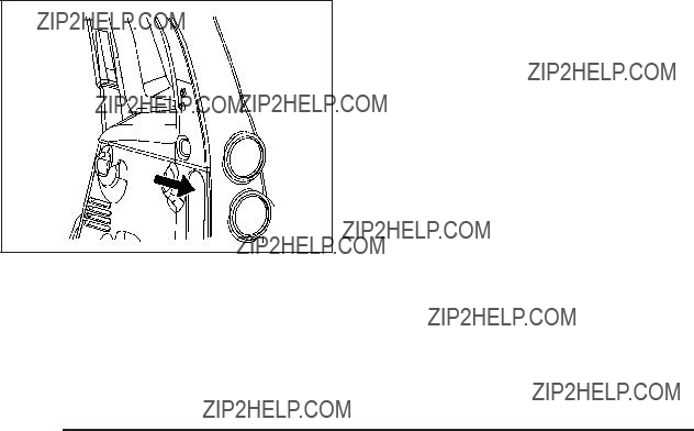
Rear Power Plug for Converters
The vehicle may have a power plug connector located in the rear cargo area on the passenger side behind the service panel. The power connector wiring can
be accessed by removing the service panel to begin installation.
This plug can be used to supply power to commercial converters and contains four different circuits. The functions of these circuits are as follows; a 40 Amp battery service, a 10 Amp Accessory or Run service, a 15 Amp Delayed Accessory service and a Ground circuit.
Notice: Adding any electrical equipment to your vehicle may damage it or keep other components from working as they should. The repairs would not be covered by your warranty. Do not use equipment exceeding maximum amperage rating of 40 amperes. Check with your dealer/retailer before adding electrical equipment.
When adding electrical equipment, be sure to follow the installation instructions included with the equipment.
Notice: Improper use of the power outlet can cause damage not covered by the warranty. Do not hang any type of accessory or accessory bracket from the plug because the power outlets are designed for accessory power plugs only.
Notice: Leaving electrical equipment plugged in for an extended period of time while the vehicle is off will drain the battery. Power is always supplied
to the outlets. Always unplug electrical equipment when not in use and do not plug in equipment that exceeds the maximum 40 ampere rating.
Ashtray(s) and Cigarette Lighter
The vehicle may have an ashtray and cigarette lighter. To use the lighter, located on the instrument panel below the climate controls, push it in all the way and let go. When it is ready, it will pop back out by itself.
Notice: Holding a cigarette lighter in while it is heating will not allow the lighter to back away from the heating element when it is hot. Damage from overheating may occur to the lighter or heating element, or a fuse could be blown. Do not hold a cigarette lighter in while it is heating. Do not use equipment exceeding maximum amperage rating of 15 amperes.
To clean the center console ashtray, remove the entire ashtray and empty it.
Notice: If papers, pins, or other ???ammable items are put in the ashtray, hot cigarettes or other smoking materials could ignite them and possibly damage the vehicle. Never put ???ammable items in the ashtray.
Climate Controls
Climate Control System
The heating, cooling, and ventilation for the vehicle can be controlled with this system.
For vehicles with remote start, the climate control system comes on and uses the prior temperature settings selected before you exited the vehicle.

9 (Off): Turn the fan control to this position to turn the fan off.
Temperature Control: Turn clockwise or counterclockwise to increase or decrease the temperature.
9 (Fan): Turn clockwise or counterclockwise to increase or decrease the fan speed. In any setting other than off, the fan runs continuously with the ignition on. The fan must be turned on to run the air conditioning (AC) compressor.
Air Delivery Mode Control: Turn clockwise or counterclockwise to change the direction of the air???ow inside the vehicle.
To change the current mode, select one of the following:
H (Vent): Air is directed to the instrument panel outlets.
)
6 (Floor): Air is directed to the ???oor outlets, with some air directed to the windshield and side windows.
- (Defog): This mode clears the windows of fog or moisture. Air is directed to the windshield, side window, and ???oor outlets. In this mode, the system runs the air conditioning compressor. To defog the windows faster, turn the temperature control knob clockwise to the warmest setting.
0 (Defrost): This mode removes fog or frost from the windshield more quickly. Air is directed to the windshield, with some air directed to the side window and ???oor outlets. In this mode, the system runs the air conditioning compressor. To defrost the windows faster, turn the temperature control knob clockwise
to the warmest setting.
# (Air Conditioning): Press to turn the air conditioning system on or off. An indicator light comes on to show that the air conditioning is on.
On hot days, open the windows to let hot inside air escape; then close them. This helps to reduce the time it takes for your vehicle to cool down. It also helps
the system to operate more efficiently.

For quick cool down on hot days:
1.Select H .
2.Select @ .
3.Select # .
4.Select the coolest temperature.
5.Select the highest fan speed.
Using these settings together for long periods of time may cause the air inside of the vehicle to become
too dry. To prevent this from happening, after the air in the vehicle has cooled, turn off the recirculation by pressing the outside air button.
The air conditioning system removes moisture from the air, so a small amount of water might drip under the vehicle while idling or after turning off the engine. This is normal.
The air conditioning compressor cannot be turned on when the fan is off.
@ (Recirculation): Press to turn the recirculation mode on. An indicator light comes on to show that recirculation is on.
This mode recirculates and helps to quickly cool the air inside the vehicle. It can be used to help prevent outside air and odors from entering the vehicle.
The air conditioning compressor also comes on. Recirculation is not available in ???oor, defog and defrost modes. If the recirculation button is pressed, the indicator light ???ashes ???ve times and outside air will be delivered. Operation in this mode during periods of high humidity and cool outside temperatures may result in increased window fogging. If window fogging is experienced, select the defrost mode.
; (Outside Air): Press to allow outside air to circulate through the vehicle. An indicator light comes on to show that outside air is on.
Rear Window Defogger
The rear window defogger uses a warming grid to remove fog from the rear window.
The rear window defogger only works when the ignition is in ON/RUN.
< (Rear): Press to turn the rear window defogger on or off. Be sure to clear as much snow from the rear window as possible. An indicator light comes on to show that the rear window defogger is on.
The rear window defogger turns off approximately 15 minutes after the button is pressed. If turned on again, the defogger only runs for approximately seven minutes before turning off.

If the vehicle speed is greater than 50 mph (80 km/h) and the rear defogger is on, it remains on as long as the speed is greater than 50 mph (80 km/h). The defogger can also be turned off by turning off the engine.
For vehicles with the remote start feature, the rear defogger automatically turns on if it is cold outside. When the vehicle transitions out of the remote start mode, the rear defogger turns off. See Remote Keyless Entry (RKE) System Operation on page
Notice: Do not use anything sharp on the inside of the rear window. If you do, you could cut or damage the warming grid, and the repairs would not be covered by the vehicle warranty. Do not attach a temporary vehicle license, tape, a decal or anything similar to the defogger grid.
Outlet Adjustment
Turn the outlets and move the outlet vanes to change the direction of the air???ow and to open and close
the outlets.
Operation Tips
???Clear away any ice, snow or leaves from the air inlets at the base of the windshield that may block the ???ow of air into the vehicle.
???Use of
???Keep the path under the front seats clear of objects to help circulate the air inside of the vehicle more effectively.
Passenger Compartment Air Filter
The ???lter removes dust and pollen from the air which is drawn into the vehicle. Air???ow reduction is an indication that the ???lter needs to be replaced.
The ???lter should be replaced as part of routine scheduled maintenance. See Scheduled Maintenance on page

To access the passenger compartment air ???lter:
1. Open and empty the glove box.
2.Press both glove box stops outward to let the glove box drop open completely.
3.Pull the three tabs of the ???lter access door down and open the access door downward.

4.Pull the ???lter out toward you, keeping it facing upwards.
Install the new air ???lter with the AIR FLOW arrow pointing downward. Reverse Steps 1 through 4 to reassemble.
Warning Lights, Gages, and
Indicators
Warning lights and gages can signal that something is wrong before it becomes serious enough to cause an expensive repair or replacement. Paying attention to the warning lights and gages could prevent injury.
Warning lights come on when there may be or is a problem with one of the vehicle???s functions. Some warning lights come on brie???y when the engine is started to indicate they are working.
Gages can indicate when there may be or is a problem with one of the vehicle???s functions. Often gages and warning lights work together to indicate a problem with the vehicle.
When one of the warning lights comes on and stays on while driving, or when one of the gages shows there may be a problem, check the section that explains what to do. Follow this manual???s advice. Waiting to do repairs can be costly and even dangerous.

Instrument Panel Cluster
The instrument panel cluster is designed to show how the vehicle is running. It shows how fast the vehicle is going, about how much fuel is left in the fuel tank, and many other things needed to drive safely and economically.
United States Manual Transmission Cluster shown, Automatic, SS and Canada similar

Speedometer and Odometer
The speedometer shows the speed in both miles per hour (mph) and kilometers per hour (km/h).
The vehicle???s odometer works together with the Driver Information Center (DIC). Trip A and Trip B can be set on the odometer. See ???Trip Information??? under DIC Operation and Displays on page
The vehicle does not have to be running to check the odometer mileage. Simply open the driver???s door and the mileage brie???y displays.
If the vehicle ever needs a new odometer installed, the new one will be set to the correct total mileage of the old odometer.
Tachometer
The tachometer displays the engine speed in revolutions per minute (RPM).
Notice: If the engine is operated with the tachometer in the red warning area, the vehicle could be damaged and the damages would not be covered by the vehicle warranty. Do not operate the engine with the tachometer in the red warning area.

Safety Belt Reminders
Safety Belt Reminder Light
When the engine is started, a chime sounds for several seconds to remind a driver to fasten the safety belt, unless the driver safety belt is already buckled.
The safety belt light comes on and stays on for several seconds, then ???ashes for several more.
This chime and light are repeated if the driver remains unbuckled and the vehicle is in motion. If the driver safety belt is already buckled, neither the chime nor the light comes on.
Passenger Safety Belt Reminder Light
Several seconds after the engine is started,
a chime sounds for several seconds to remind the front passenger to buckle their safety belt.
This only occurs if the passenger airbag is enabled. See Passenger Sensing System (Without Turbo/With Turbo and RPO AS5) on page
This chime and light are repeated if the passenger remains unbuckled and the vehicle is in motion.
If the passenger safety belt is buckled, neither the chime nor the light comes on.
The front passenger safety belt warning light and chime may turn on if an object is put on the seat such as a briefcase, handbag, grocery bag, laptop or other electronic device. To turn off the warning light and or chime, remove the object from the seat or buckle the safety belt.
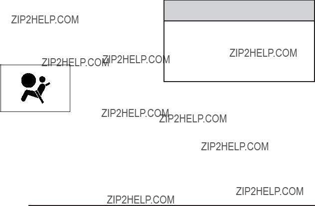
Airbag Readiness Light
The system checks the airbag???s electrical system for possible malfunctions. If the light stays on it indicates there is an electrical problem. The system check includes the airbag sensor, the pretensioners, the airbag modules, the wiring and the crash sensing and diagnostic module. For more information on the airbag system, see Airbag System on page
The airbag readiness light ???ashes for a few seconds when the engine is started. If the light does not come on then, have it ???xed immediately.
{ CAUTION:
If the airbag readiness light stays on after the vehicle is started or comes on while driving, it means the airbag system might not be working properly. The airbags in the vehicle might not in???ate in a crash, or they could even in???ate without a crash. To help avoid injury, have the vehicle serviced right away.
If there is a problem with the airbag system, an airbag Driver Information Center (DIC) message can also come on. See DIC Warnings and Messages on page
for more information.
Passenger Airbag Status Indicator
The vehicle has the passenger sensing system.
See Passenger Sensing System (Without Turbo/With Turbo and RPO AS5) on page
When the vehicle is started, the passenger airbag status indicator will light ON and OFF, or the symbol for on and off, for several seconds as a system check. If you are using remote start to start the vehicle from a distance, if equipped, you may not see the system check. Then, after several more seconds, the status indicator will light either ON or OFF, or either the on or off symbol to let you know the status of the right front passenger frontal airbag.
If the word ON or the on symbol is lit on the passenger airbag status indicator, it means that the right front passenger frontal airbag is enabled (may in???ate).
If the word OFF or the off symbol is lit on the airbag status indicator, it means that the passenger sensing system has turned off the right front passenger frontal airbag.
If, after several seconds, both status indicator lights remain on, or if there are no lights at all, there may be a problem with the lights or the passenger sensing system. See your dealer/retailer for service.
{ CAUTION:
If the airbag readiness light ever comes on and stays on, it means that something may be wrong with the airbag system. To help avoid injury to yourself or others, have the vehicle serviced right away. See Airbag Readiness Light on page

This light comes on brie???y when the ignition key is turned on, but the engine is not running, as a check
to show it is working.
It should go out once the engine is running. If it stays on, or comes on while driving, there could be a problem with the charging system or it could indicate that there are problems with a generator drive belt, or that there is an electrical problem. Have it checked right away. If the vehicle must be driven a short distance with the light on, to turn off the accessories, such as the radio and air conditioner.
The vehicle may have an
When this light comes on, shift to the next higher gear if weather, road, and traffic conditions allow.
See Manual Transmission Operation on page
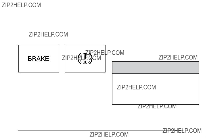
Brake System Warning Light
The vehicle???s hydraulic brake system is divided into two parts. If one part is not working, the other part can
still work and stop the vehicle. For good braking both parts need to be working well.
If the warning light comes on, there is a brake problem. Have the brake system inspected right away.
This light should come on brie???y when the engine is started. If it does not come on then, have it ???xed so it will be ready to warn if there is a problem.
When the ignition is on, the brake system warning light also comes on when the parking brake is set. The light stays on if the parking brake does not fully release. If it stays on after the parking brake is fully released, it means the vehicle has a brake problem.
If the light comes on while driving, pull off the road and stop carefully. Make sure the parking brake is fully
released. The pedal might be harder to push or, the pedal could go closer to the ???oor. It can take longer to stop.
Try turning off and restarting the vehicle one or two times, if the light is still on, have the vehicle towed for service. See Towing Your Vehicle on page
{ CAUTION:
The brake system might not be working properly if the brake system warning light is on. Driving with the brake system warning light on can lead to a crash. If the light is still on after the vehicle has been pulled off the road and carefully stopped, have the vehicle towed for service.

For vehicles with the Antilock Brake System (ABS), this light comes on brie???y when the engine is started.
For vehicles with the Enhanced Traction System (ETS), this light serves
as an indicator and warning light.
If it does not, have the vehicle serviced by your dealer/retailer. If the system is working normally the indicator light then goes off.
If the ABS light stays on, turn the ignition off. If the light comes on while driving, stop as soon as it is safely possible and turn the ignition off. Then start the engine again to reset the system. If the ABS light stays on, or comes on again while driving, the vehicle needs service. If the regular brake system warning light is not on, the vehicle still has brakes, but not antilock brakes. If the regular brake system warning light is also on, the vehicle does not have antilock brakes and there is a problem with the regular brakes. See Brake System Warning Light on page
For vehicles with a Driver Information Center (DIC), see
DIC Warnings and Messages on page
This light comes on brie???y while the engine is started. If it does not, have the vehicle serviced by your dealer/ retailer. If the system is working normally the indicator light then goes off.
If the indicator/warning light is on and not ???ashing, the ETS system could have been disabled. Check all related Driver Information Center (DIC) messages to determine whether the system has been turned off or if the system is not working properly and the vehicle requires service. If the ETS has been disabled, wheel spin is not limited.
If the indicator/warning light is on and ???ashing, the ETS is actively working. The LOW TRACTION DIC message also appears when the system is actively limiting wheel spin.
See Enhanced Traction System (ETS) on page

Electronic Stability Control (ESC)/
Traction Control System (TCS)
Indicator/Warning Light
The Electronic Stability Control (ESC) system or the Traction Control System (TCS) indicator/ warning light comes on brie???y when the engine is started.
If it does not, have the vehicle serviced by the dealer/retailer. If the system is working normally the indicator light goes off.
This light, along with the appropriate Driver Information Center (DIC) messages, indicates when the ESC system and the TCS are working or are disabled.
If the light comes on and stays on, the TCS and potentially the ESC system have been disabled.
Check the DIC messaging to determine which system is turned off, or not working. If the system is not working, the vehicle needs service. See your dealer/retailer.
When the TCS is disabled, wheel spin is not limited. When the ESC system is disabled, the system does not aid in maintaining vehicle directional control.
If the light comes on and ???ashes, the TCS or the ESC system is actively working. When the LOW TRACTION message appears, the system is limiting wheel spin.
When the ESC ACTIVE message appears, the system is aiding in maintaining vehicle directional control.
See Electronic Stability Control (ESC) on page
See DIC Warnings and Messages on page
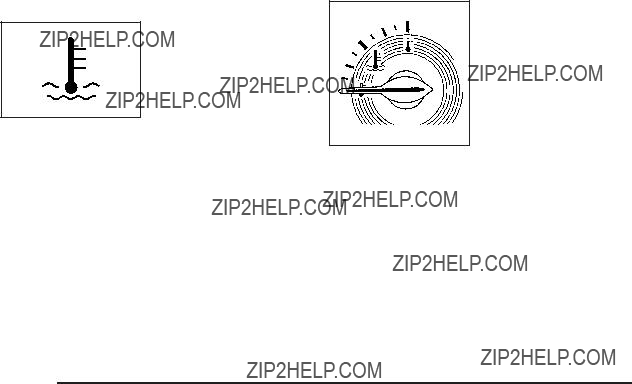
Engine Coolant Temperature
Warning Light
This light comes on brie???y while starting the vehicle.
If it does not, have the vehicle serviced by the dealer/retailer. If the system is working normally the indicator light goes off.
Notice: Driving with the engine coolant temperature warning light on could cause the vehicle to overheat. See Engine Overheating on page
The engine coolant temperature warning light comes on when the engine has overheated.
If this happens pull over and turn off the engine as soon as possible. See Engine Overheating on page
for more information.
Engine Coolant Temperature Gage
The vehicle has an engine coolant temperature gage. With the ignition turned to ON/RUN, this gage shows the engine coolant temperature.
If the gage pointer moves into the red area, the engine is too hot because the engine coolant has overheated.
If the vehicle is operating under normal driving conditions, pull off the road, stop the vehicle and turn off the engine as soon as possible.
See Engine Overheating on page

Tire Pressure Light
For vehicles with a tire pressure monitoring system, this light comes on brie???y when the engine is started.
It provides information about tire pressures and the Tire Pressure Monitoring System.
When the Light is On Steady
This indicates that one or more of the tires is signi???cantly underin???ated.
A tire pressure message in the Driver Information Center (DIC), can accompany the light. See DIC Warnings and Messages on page
When the Light Flashes First and Then is On Steady
This indicates that there could be a problem with the Tire Pressure Monitor System. The light ???ashes for about a minute and stays on steady for the remainder of the ignition cycle. This sequence repeats with every ignition cycle. See Tire Pressure Monitor System on page
Malfunction Indicator Lamp
Check Engine Light
A computer system called OBD II
It ensures that emissions are at acceptable levels for the life of the vehicle, helping to produce a cleaner environment.

This light should come on when the ignition is on, but the engine is not running, as a check to show it
is working. If it does not, have the vehicle serviced by your dealer/retailer.
If the check engine light comes on and stays on, while the engine is running, this indicates that there is an OBD II problem and service is required.
Malfunctions often are indicated by the system before any problem is apparent. Being aware of the light can prevent more serious damage to the vehicle. This system assists the service technician in correctly diagnosing any malfunction.
Notice: If the vehicle is continually driven with this light on, after a while, the emission controls might not work as well, the vehicle???s fuel economy might not be as good, and the engine might not run as smoothly. This could lead to costly repairs that might not be covered by the vehicle warranty.
Notice: Modi???cations made to the engine, transmission, exhaust, intake, or fuel system of the vehicle or the replacement of the original tires with other than those of the same Tire Performance Criteria (TPC) can affect the vehicle???s emission controls and can cause this light to come on. Modi???cations to these systems could lead to costly repairs not covered by the vehicle warranty. This could also result in a failure to pass a required Emission Inspection/Maintenance test. See
Accessories and Modi???cations on page
This light comes on during a malfunction in one of two ways:
Light Flashing: A mis???re condition has been detected. A mis???re increases vehicle emissions and could damage the emission control system on the vehicle. Diagnosis and service might be required.
To prevent more serious damage to the vehicle:
???Reduce vehicle speed.
???Avoid hard accelerations.
???Avoid steep uphill grades.
???If towing a trailer, reduce the amount of cargo being hauled as soon as it is possible.

If the light continues to ???ash, when it is safe to do so, stop the vehicle. Find a safe place to park the vehicle. Turn the key off, wait at least 10 seconds, and restart the engine. If the light is still ???ashing, follow the previous steps and see your dealer/retailer for service as soon as possible.
Light On Steady: An emission control system malfunction has been detected on the vehicle. Diagnosis and service might be required.
An emission system malfunction might be corrected by doing the following:
???Make sure the fuel cap is fully installed. See Filling the Tank on page
A few driving trips with the cap properly installed should turn the light off.
???If the vehicle has been driven through a deep puddle of water, the vehicle???s electrical system might be wet. The condition is usually corrected when the electrical system dries out. A few driving trips should turn the light off.
???Make sure to fuel the vehicle with quality fuel. Poor fuel quality causes the engine not to run as efficiently as designed and can cause: stalling after
If one or more of these conditions occurs, change the fuel brand used. It will require at least one full tank of the proper fuel to turn the light off.
See Gasoline Octane on page
If none of the above have made the light turn off, your dealer/retailer can check the vehicle. The dealer/retailer has the proper test equipment and diagnostic tools to ???x any mechanical or electrical problems that might have developed.

Emissions Inspection and Maintenance
Programs
Some state/provincial and local governments have or might begin programs to inspect the emission control equipment on the vehicle. Failure to pass this inspection could prevent getting a vehicle registration.
Here are some things to know to help the vehicle pass an inspection:
???The vehicle will not pass this inspection if the check engine light is on with the engine running, or if the key is in ON/RUN and the light is not on.
???The vehicle will not pass this inspection if the OBD II
Oil Pressure Light
{ CAUTION:
Do not keep driving if the oil pressure is low.
The engine can become so hot that it catches ???re. Someone could be burned. Check the oil as soon as possible and have the vehicle serviced.
Notice: Lack of proper engine oil maintenance can damage the engine. The repairs would not be covered by the vehicle warranty. Always follow the maintenance schedule in this manual for changing engine oil.
This light comes on brie???y while starting the engine.
If it does not, have the vehicle serviced by your dealer/ retailer. If the system is working normally the indicator light then goes off.
If the light comes on and stays on, it means that oil is not ???owing through the engine properly. The vehicle could be low on oil and it might have some other system problem.
Security Light
For information regarding this light and the vehicle???s security system, see
Content
Fog Lamp Light
The fog lamp light comes on when the fog lamps are in use.
The light goes out when the fog lamps are turned off. See Fog Lamps on page
Highbeam On Light
This light comes on when the
See Headlamp

Fuel Gage
The fuel gage indicates about how much fuel is left in the fuel tank.
An arrow on the fuel gage indicates the side of the vehicle the fuel door is on.
Here are four things that some owners ask about. None of these show a problem with the fuel gage:
???At the service station, the gas pump shuts off before the gage reads full.
???It takes a little more or less fuel to ???ll up than the gage indicated. For example, the gage may have indicated the tank was half full, but it actually took a little more or less than half the fuel tank???s capacity to ???ll it.
???The gage moves a little when the vehicle turns a corner or speeds up.
???The gage does not go back to empty when the ignition is turned off.
For the fuel tank capacity, see Capacities and Speci???cations on page
Boost Gage
For vehicles with this gage, it indicates vacuum during light to moderate throttle and boost under heavier throttle.

This gage displays the air pressure level in the intake manifold before it enters the engine???s combustion chamber.
It is automatically centered at zero every time the engine is started. Actual vacuum or boost is displayed from this zero point. Changes in ambient pressure, such as driving in mountains and changing weather, will slightly change the zero reading.
Recon???gurable Performance
Display (RPD)
For vehicles with the RPD, the screen displays information that can be used to monitor vehicle performance. The RPD knob located next to the screen is used to con???gure the display and select information to be viewed.
A short video plays whenever the ignition key is turned on. Press the RPD knob to stop the video and go directly to RPD displays.
RPD Screen Example US Version Shown, Canada Similar (French Display Currently Not Available)
The RPD screen displays two divided areas (A, B) of information called Regions. Advance through Region A screens to show various gages and speedometer displays. Advance through Region B screens to show digital readouts and indicator information.
The position of these regions can be reversed. See the SETUP MENU for more information.
When the ignition is turned off and then back on, the RPD shows the last screen displayed.

Region A Gage and Speedometer
Displays
Change the information displayed in Region A by turning the knob either clockwise or counterclockwise. The available gages are:
BOOST: Displays positive boost pressure as determined by the manifold air pressure (MAP) sensor.
AIR/FUEL RATIO: Displays the mass ratio of air to fuel.
CAM PHASER ANGLES: Displays orientation of the intake and exhaust cam shafts relative to their park positions as commanded by the engine control module. OVERLAP represents the total distance the intake and exhaust cam shafts have phased.
SPARK ADVANCE/ KNOCK RETARD: The spark advance gage displays ignition timing. Knock retard indicates the amount of ignition delay to reduce spark knock.
ENGINE POWER & TORQUE: Displayed engine power and torque are engine ???ywheel output values calculated by the engine control module. These values are approximate and may change with the air conditioning load, generator output, air temperature, air pressure, and fuel octane.
SPEEDOMETER & G FORCE: The G FORCE meter displays lateral acceleration. While turning right, G forces are felt on the left, and vice versa. PEAK values are stored inde???nitely, and can be reset with a press and hold of the RPD knob while viewing the G FORCE meter.
SETUP MENU: Press the RPD knob to enter this menu. The vehicle should be stopped while con???guring the setup menu selections.
SCREEN OFF: Turns the screen off.
Region B Readout Displays
Press the RPD knob to highlight Region B. The information displayed can be changed by turning the RPD knob either clockwise or counterclockwise. Press the RPD knob again, to store the selection. The selection will also be stored after a few seconds of no activity. Available modes are:
Readouts #1
SHIFT LIGHTS/GEAR INDICATION: The shift lights provide visual identi???cation of engine speed for a transmission gear. Shift light minimum and maximum RPM settings can be viewed and con???gured in the SETUP screen.
Readouts #2
TIRE PRESSURES: Displays the last gage tire pressures recorded from each of the wheel mounted tire pressure sensors.
Readouts #3
BAROMETER: Displays ambient air pressure as measured by the engine???s ambient pressure sensor.
OUTSIDE TEMPERATURE: Displays ambient temperature as measured by an outside air temperature sensor.
BATTERY VOLTAGE: Displays the vehicle???s battery voltage.
Readouts #4
COOLANT TEMPERATURE: Displays engine coolant temperature as measured by a coolant temperature sensor.
INLET AIR TEMPERATURE: Displays the instantaneous temperature of the air at the inlet to the induction system.
FUEL PRESSURE: Displays fuel pressure as measured by a sensor on the output of the
INDICATORS
The indicators come on when the corresponding function is actively working to stabilize or control the vehicle. Each indicator light on the RPD display can be turned on and off using the SETUP MENU. These indicators work independently of the telltales on the instrument panel cluster. Turning the indicator on the RPD display on or off does not enable or disable the functions on the vehicle.
This indicator comes on whenever the vehicle StabiliTrak?? is actively working.

This indicator comes on when Competitive Driving Mode (A) has been set using the traction control switch. This telltale comes on whenever conditions are right
for the Launch Mode (B) to activate.
See Electronic Stability Control (ESC) on page
SETUP MENU
The SETUP MENU allows for the appearance of each display screen to be customized. Turn the knob to scroll through the screens to reach the SETUP MENU. Press and release the knob to activate the SETUP MENU.
This indicator comes on whenever the vehicle Traction Control system is actively working.
Selecting a SETUP MENU Option
1.Under SETUP MENU there are six menu options to choose. Turn the RPD knob to highlight an option.
2.Press and release the RPD knob to select the highlighted menu option.

SETUP MENU Options
GAUGE APPEARANCE: While the gage is highlighted, press the RPD knob. Then turn the knob to choose
the background color for a gage. Press the knob again when gage color is chosen.
SHIFT LIGHT SETUP: This screen establishes a RPM range where the shift light comes on for each gear. Turn the RPD knob to highlight a shift light setting. Press the knob to allow adjustment of the highlighted setting. Turn the knob to adjust the value up or down, then press the knob again to allow the selection of another item. The number above each gear shows
the highest RPM the light comes on for a gear range. The number below each gear indicates the lowest RPM the light comes on for a gear range.
INDICATORS ON/OFF: Select on or off for each indicator by turning the RPD knob to highlight ON or OFF. Press and Release the RPD knob to apply the choice. The actual Traction Control, StabiliTrak??, Competitive Mode, Launch Control functions and instrument panel cluster telltales are not enabled or disabled by these indicators.
SCREEN ORDER: While the screen order is highlighted, press the knob to allow adjustment. Turn the knob to reverse the displayed order of Region A and Region B. Press the knob again once the screen is chosen.
CONTRAST: While the contrast slider is highlighted, press the knob to allow adjustment. Turn the knob to adjust the contrast of the screen. Press the knob again when the desired contrast is reached.
RESTORE DEFAULTS: Restores the original factory screen defaults.
Applying a SETUP MENU Option
After each screen is customized, use this procedure to apply the change and return to the SETUP MENU.
SET: Applies the changes to the display.
1.Turn until SET is highlighted.
2.Press and release while SET is highlighted to lock in the setting and return to the previous screen.
RETURN /RET: Returns the display to the previous screen without saving changes.
1.Turn to highlight the RETURN/RET option.
2.Press and release knob to return to the previous menu.

Driver Information Center (DIC)
Your vehicle has a Driver Information Center (DIC). The DIC display gives you the status of many of your vehicle???s systems. The DIC is also used to display driver personalization menu modes and warning/status messages. All messages will appear in the DIC display, located at the bottom of the instrument panel cluster.
The DIC buttons are located on the left side of the steering wheel.
INFO (Information): Press this button to scroll through the vehicle information mode displays.
r (Reset): Press this button to reset some vehicle information mode displays, select a personalization menu mode setting, or acknowledge a warning message.
Press and hold the information and reset buttons at the same time for one second, then release the buttons
to enter the personalization menu. See DIC Vehicle Personalization on page
DIC Operation and Displays
The DIC comes on when the ignition is on. The DIC has different modes which can be accessed by pressing
the DIC buttons. The button functions are detailed in the following.
Information Modes
INFO (Information): Press this button to scroll through the following vehicle information modes:
Outside Air Temperature and Odometer
Press the information button until the outside air temperature and the odometer display. This mode shows the temperature outside of the vehicle in either degrees Fahrenheit (??F) or degrees Celsius (??C) and the total distance the vehicle has been driven in either miles (mi) or kilometers (km). The outside air temperature appears on the left side of the DIC display and the odometer appears on the right side of the display.
To change the DIC display to English or metric units, see ???UNITS??? under DIC Vehicle Personalization on page

TRIP A or TRIP B
Press the information button until TRIP A or TRIP B display. These modes show the current distance traveled since the last reset for each trip odometer in either miles (mi) or kilometers (km). Both odometers can be used at the same time.
To reset the trip odometer to zero, press and hold the reset button for a few seconds while the desired
trip odometer is displayed.
FUEL RANGE
Press the information button until FUEL RANGE displays. This mode shows the remaining distance you can drive without refueling in either miles (mi) or kilometers (km).
It is based on fuel economy and the fuel remaining in the tank.
When the fuel level is low, FUEL RANGE LOW displays.
The fuel economy data used to determine fuel range is an average of recent driving conditions. As your driving conditions change, this data is gradually updated.
The FUEL RANGE mode cannot be reset.
MPG (L/100 KM) AVG (Average)
Press the information button until MPG (L/100 KM) AVG displays. This mode shows how many miles per
gallon (mpg) or liters per 100 kilometers (L/100 km) your vehicle is getting based on current and past driving conditions.
To reset the average fuel economy, press and hold the reset button while MPG (L/100 KM) AVG is displayed. Average fuel economy is then calculated starting
from that point. If the average fuel economy is not reset, it is continually updated each time you drive.
MPG (L/100 KM) INST (Instantaneous)
Press the information button until MPG (L/100 KM) INST displays. This mode shows the current fuel economy
at a particular moment and changes frequently as driving conditions change. This mode shows the instantaneous fuel economy in miles per gallon (mpg) or liters per 100 kilometers (L/100 km). Unlike average fuel economy, this screen cannot be reset.
AV (Average) SPEED
Press the information button until AV SPEED displays. This mode shows the vehicle???s average speed in miles per hour (mph) or kilometers per hour (km/h).
To reset the average vehicle speed, press and hold the reset button while AV SPEED is displayed.

OIL LIFE
Press the information button until OIL LIFE displays. The engine oil life system shows an estimate of the oil???s remaining useful life. It shows 100% when the system is reset after an oil change. It alerts you to change the oil on a schedule consistent with your driving conditions.
In addition to the engine oil life system monitoring the oil life, additional maintenance is recommended in the Maintenance Schedule in this manual. See Engine Oil on page
Always reset the engine oil life system after an oil change. See ???How to Reset the Engine Oil Life System??? under Engine Oil Life System on page
COOLANT
Press the information button until COOLANT displays. This mode shows the temperature of the engine coolant in either degrees Fahrenheit (??F) or degrees Celsius (??C).
Tire Pressure
If your vehicle has a Tire Pressure Monitor System (TPMS), the pressure for each tire can be viewed in the DIC. The tire pressure is shown in either pounds per square inch (psi) or kilopascals (kPa). Press the information button until LF ## PSI (kPa) ## RF displays for the front tires. Press the information button again until LR ## PSI (kPa) ## RR displays for the rear tires.
If a low tire pressure condition is detected by the system while driving, a message advising you to check the tire pressure appears in the display. See In???ation - Tire Pressure on page
DIC Warnings and Messages
These messages appear if there is a problem detected in one of your vehicle???s systems.
A message clears when the vehicle???s condition is no longer present. To acknowledge a message and clear it from the display, press and hold any of the DIC buttons. If the condition is still present, the warning message comes back on the next time the vehicle is turned off and back on. With most messages, a warning chime sounds when the message displays. Your vehicle may have other warning messages.
AUTO (Automatic) LIGHTS OFF
This message displays if the automatic headlamp system is disabled with the headlamp switch. See Automatic Headlamp System on page
AUTO (Automatic) LIGHTS ON
This message displays if the automatic headlamp system is enabled with the headlamp switch. See Automatic Headlamp System on page
BRAKE FLUID
This message displays, while the ignition is on, when the brake ???uid level is low. The brake system warning light on the instrument panel cluster also comes on.
See Brake System Warning Light on page
CHANGE OIL SOON
This message displays when the life of the engine oil has expired and it should be changed.
When this message is acknowledged and cleared from the display, the engine oil life system must still be reset separately. See Engine Oil Life System on page
CHECK GAS CAP
This message displays if the fuel cap has not been fully tightened. Recheck the fuel cap to make sure that it
is on properly. A few driving trips with the cap properly installed should turn the message off.
CHECK TIRE PRESS (Pressure)
If your vehicle has a Tire Pressure Monitor System (TPMS), this message displays when the pressure in one or more of the vehicle???s tires needs to be checked. If a tire pressure message appears on the DIC, stop as soon as you can. Have the tire pressures checked and set to those shown on the Tire Loading Information label. See Tires on page
See Tire Pressure Light on page
COMPETITIVE MODE
If your vehicle has this feature, this message displays when the Competitive Driving mode is selected.
The Traction Control System (TCS) will not be operating while in the Competitive Driving mode and the ESC/TCS light on the instrument panel cluster will be on solid.
Adjust your driving accordingly. See Traction Control System (TCS) on page

COOLING MODE ON
This message may display on some vehicles. Under severe conditions, hot ambient temperatures, steep grades, and towing, your vehicle may experience more transmission shifting. This is temporary and normal under these conditions. This does not require engine or transmission service.
CRUISE ENGAGED
This message displays when the cruise control system is active. See Cruise Control on page
DOOR AJAR
This message displays if one or more of the vehicle???s doors are open. Make sure that the door(s) are closed completely.
ENGINE DISABLED
This message displays if the starting of the engine is disabled. Have your vehicle serviced by your dealer/ retailer immediately.
ENG (Engine) PWR (Power) REDUCED
This message displays to inform you that the vehicle
has reduced engine power to avoid damaging the engine. Reduced engine power can affect the vehicle???s ability
to accelerate. If this message is on, but there is no reduction in performance, proceed to your destination. The performance may be reduced the next time the vehicle is driven. The vehicle may be driven at a reduced speed while this message is on, but acceleration and speed may be reduced. Anytime this message stays on, the vehicle should be taken to your dealer/retailer for service as soon as possible.
ESC (Electronic Stability Control) ACTIVE
If your vehicle has Electronic Stability Control (ESC), this message displays and the ESC/TCS light on the instrument panel cluster ???ashes when ESC is assisting you with directional control of the vehicle. You may feel or hear the system working and see this message displayed in the DIC. Slippery road conditions may exist when this message is displayed, so adjust your driving accordingly. This message may stay on for a few seconds after ESC stops assisting you with directional control of the
vehicle. This is normal when the system is operating. See Electronic Stability Control (ESC) on page

ESC (Electronic Stability Control) NOT
READY
If your vehicle has Electronic Stability Control (ESC), this message may display brie???y after starting the vehicle if the system???s sensors are not yet calibrated. The system is not functional until the message stops displaying. Adjust your driving accordingly. When the message is no longer displayed, the system is functional. See Electronic Stability Control (ESC) on page
ESC (Electronic Stability Control) OFF
If your vehicle has Electronic Stability Control (ESC), this message displays and the ESC/TCS light on the instrument panel cluster comes on solid when ESC is turned off. Adjust your driving accordingly. See Electronic Stability Control (ESC) on page
GATE AJAR
This message displays when the liftgate is open. Make sure that the liftgate is closed completely. See Liftgate on page
ICE POSSIBLE
This message displays when the outside air temperature is cold enough to create icy road conditions. Adjust your driving accordingly.
KEY FOB BATT (Battery) LOW
This message displays if the Remote Keyless Entry (RKE) transmitter battery is low. Replace the battery in the transmitter. See ???Battery Replacement??? under
Remote Keyless Entry (RKE) System Operation on page
LAUNCH CONTROL
If your vehicle has this feature, this message displays after the COMPETITIVE MODE message when the vehicle is stopped. Launch control is a form of traction control to control wheel spin while launching the vehicle during closed track events and competitive driving venues. The system will exit to COMPETITIVE MODE after the vehicle is launched. See ???COMPETITIVE MODE??? earlier in this section. See ???Launch Control??? under Electronic Stability Control (ESC) on page

LOW FUEL
This message displays when your vehicle is low on fuel. Re???ll the fuel tank as soon as possible. See Fuel Gage on page
LOW TRACTION
If your vehicle has the Enhanced Traction System (ETS) or Traction Control System (TCS), this message displays and the ETS light or the ESC/TCS light on the instrument panel cluster ???ashes when the system is actively limiting wheel spin. Slippery road conditions may exist if this message is displayed, so adjust your driving accordingly. This message stays on for a few seconds after the system stops limiting wheel spin. See Enhanced Traction System (ETS) on page
PARKING BRAKE
This message displays if the parking brake is left engaged. See Parking Brake on page
POWER STEERING
This message displays if a problem has been detected with the electric power steering. Have your vehicle serviced by your dealer/retailer immediately.
SERVICE AIR BAG
This message displays when there is a problem with the airbag system. Have your vehicle serviced by your dealer/retailer immediately.
SERVICE ESC (ELECTRONIC STABILITY
CONTROL)
If your vehicle has Electronic Stability Control (ESC), this message displays and a chime sounds if there has been a problem detected with ESC. The ESC/TCS light also appears on the instrument panel cluster. This light stays on solid as long as the detected problem remains present. When this message displays, the system is not working. Adjust your driving accordingly. See Electronic Stability Control (ESC) on page

If this message turns on while you are driving, pull off the road as soon as possible and stop carefully. Try resetting the system by turning the ignition off and then back on.
If this message still stays on or turns back on again while you are driving, your vehicle needs service. Have the ESC inspected by your dealer/retailer as soon as possible.
SERVICE TRACTION
If your vehicle has the Enhanced Traction System (ETS) or Traction Control System (TCS), this message displays and a chime sounds when the system is not functioning properly. The ETS light or the ESC/TCS light also appears on the instrument panel cluster. This light stays on solid as long as the detected problem remains present. When this message displays, the system is not working. Adjust your driving accordingly. See Enhanced Traction System (ETS) on page
SVC (Service) BRAKE SYSTEM
This message may display if you have a turbocharged vehicle with Electronic Stability Control (ESC) and if the hydraulic brake boost is not working or is working improperly. Have the brake system serviced by your dealer/retailer as soon as possible.
SVC (Service) TIRE MONITOR
If your vehicle has a Tire Pressure Monitor System (TPMS), this message displays if a part on the TPMS is not working properly. The tire pressure light also ???ashes and then remains on during the same ignition cycle. See
Tire Pressure Light on page
TRACTION OFF
If your vehicle has the Enhanced Traction System (ETS) or Traction Control System (TCS), this message displays and the ETS light or the ESC/TCS light on the instrument panel cluster comes on solid when the system is turned off. Adjust your driving accordingly. See Enhanced Traction System (ETS) on page

DIC Vehicle Personalization
Your vehicle has personalization capabilities that allow you to program certain features to a preferred setting. All of the features listed may not be available on your vehicle. Only the features available will be displayed on the DIC.
The default settings for the features were set when your vehicle left the factory, but may have been changed from their default state since that time.
To change feature settings, use the following procedure:
Entering Personalization Menu
1.Turn the ignition on while the vehicle is stopped.
To avoid excessive drain on the battery, it is recommended that the headlamps are turned off.
2.Press and hold the information and reset buttons at the same time for one second, then release to enter the personalization menu.
If the vehicle speed is greater than 2 mph (3 km/h), only the UNITS menu will be accessible.
3.Press the information button to scroll through the available personalization menu modes.
Press the reset button to scroll through the available settings for each mode.
If you do not make a selection within ten seconds, the display will go back to the previous information displayed.
Personalization Menu Modes
OIL LIFE RESET
When this feature is displayed, you can reset the engine oil life system. To reset the system, see Engine Oil Life System on page

UNITS
This feature allows you to select the units of measurement in which the DIC will display the vehicle information. When UNITS appears on the display, press and hold the reset button for at least one second to scroll through the available settings:
ENGLISH (default in United States): All information will be displayed in English units.
METRIC (default in Canada): All information will be displayed in metric units.
To select a setting and move on to the next feature, press the information button while the desired setting is displayed on the DIC.
REMOTE START
If your vehicle has remote start, this feature allows remote start to be turned off or on. Remote start allows you to start the engine from outside of the vehicle using your Remote Keyless Entry (RKE) transmitter. When REMOTE START appears on the display, press and hold the reset button for at least one second to scroll through the available settings:
OFF: The remote start feature will be disabled.
ON (default): The remote start feature will be enabled.
See Remote Vehicle Start on page
To select a setting and move on to the next feature, press the information button while the desired setting is displayed on the DIC.
LOCK HORN
This feature, which allows the vehicle???s horn to chirp every time the lock button on the Remote Keyless Entry (RKE) transmitter is pressed, can be enabled or disabled. When LOCK HORN appears on the display, press and hold the reset button for at least one second to scroll through the available settings:
OFF (default): The horn will not chirp on the ???rst press of the lock button on the RKE transmitter. The horn will still chirp on the second press.
ON: The horn will chirp on the ???rst press of the lock button on the RKE transmitter.
See Remote Keyless Entry (RKE) System Operation on page
To select a setting and move on to the next feature, press the information button while the desired setting is displayed on the DIC.

UNLOCK HORN
This feature, which allows the vehicle???s horn to chirp on the ???rst press of the unlock button on the Remote Keyless Entry (RKE) transmitter, can be enabled or disabled. When UNLOCK HORN appears on the display, press and hold the reset button for at least one second to scroll through the available settings:
OFF (default): The horn will not chirp when the unlock button on the RKE transmitter is pressed.
ON: The horn will chirp on the ???rst press of the unlock button on the RKE transmitter.
See Remote Keyless Entry (RKE) System Operation on page
To select a setting and move on to the next feature, press the information button while the desired setting is displayed on the DIC.
LIGHT FLASH
This feature, which allows the vehicle???s exterior hazard/turn signal lighting to ???ash every time the lock or unlock button on the Remote Keyless Entry (RKE) transmitter is pressed, can be enabled or disabled.
When LIGHT FLASH appears on the display, press and hold the reset button for at least one second to scroll through the available settings:
OFF: The exterior hazard/turn signal lighting will not ???ash when the lock or unlock button on the RKE transmitter is pressed.
ON (default): The exterior hazard/turn signal lighting will ???ash when the lock or unlock button on the RKE transmitter is pressed.
See Remote Keyless Entry (RKE) System Operation on page
To select a setting and move on to the next feature, press the information button while the desired setting is displayed on the DIC.
DELAY LOCK
This feature, which delays the actual locking of the vehicle, can be enabled or disabled. When DELAY LOCK appears on the display, press and hold the reset button for at least one second to scroll through the available settings:
ON (default): The doors will not lock until ???ve seconds after the last door is closed. You can temporarily override delayed locking by pressing the power lock switch or
the lock button on the Remote Keyless Entry (RKE) transmitter a second time.

OFF: The doors will lock immediately when pressing the power lock switch or the lock button on the
RKE transmitter.
See Power Door Locks on page
To select a setting and move on to the next feature, press the information button while the desired setting is displayed on the DIC.
AUTO UNLK (Unlock)
This feature, which allows the vehicle to automatically unlock certain doors, can be enabled or disabled. When AUTO UNLK appears on the display, press and hold the reset button for at least one second to scroll through the available settings:
ALL (default): All of the doors will automatically unlock.
DRIVER: The driver???s door will automatically unlock.
NONE: None of the doors will automatically unlock. You will need to manually unlock the doors.
If you have a manual transmission vehicle, the door(s) will automatically unlock when the key is turned off.
If you have an automatic transmission vehicle, you can select when the automatic unlocking will occur. See ???UNLK (Unlock) (Automatic Transmission Only)??? following.
See Programmable Automatic Door Unlock on page
To select a setting and move on to the next feature, press the information button while the desired setting is displayed on the DIC.
UNLK (Unlock) (Automatic
Transmission Only)
This screen displays only if your vehicle has an automatic transmission and DRIVER or ALL is selected for the AUTO UNLK feature. This feature determines when the automatic door unlocking will occur. When UNLK appears on the display, press and hold the reset button for at least one second to scroll through the available settings:
KEY OFF: The door(s) will unlock when the key is turned off.
SHIFT TO P (Park) (default): The door(s) will unlock when the vehicle is shifted into P (Park).
See Programmable Automatic Door Unlock on page
To select a setting and move on to the next feature, press the information button while the desired setting is displayed on the DIC.

EXT (Exterior) LIGHTS
This feature, which allows the vehicle???s exterior perimeter lighting to turn on each time the unlock button on the Remote Keyless Entry (RKE) transmitter is pressed, can be enabled or disabled. When EXT LIGHTS appears on the display, press and hold the reset button for at least one second to scroll through the available settings:
OFF: The exterior perimeter lighting will not turn on when the unlock button on the RKE transmitter is pressed.
ON (default): The exterior perimeter lighting will turn on when the unlock button on the RKE transmitter
is pressed.
See Remote Keyless Entry (RKE) System Operation on page
To select a setting and move on to the next feature, press the information button while the desired setting is displayed on the DIC.
LANGUAGE
This feature allows you to select the language in which the DIC will display. When LANGUAGE appears on the display, press and hold the reset button for at least one second to scroll through the available settings:
ENGLISH (default): All messages will appear in English.
FRENCH: All messages will appear in French.
SPANISH: All messages will appear in Spanish.
GERMAN: All messages will appear in German.
To select a setting and exit out of the personalization menu mode, press the information button while the desired setting is displayed on the DIC.
Exiting Personalization Menu
The personalization menu will be exited when any of the following conditions occur:
???A ten second time period has elapsed.
???The ignition is turned off.
???The end of the personalization menu list is reached.
Audio System(s)
Determine which radio the vehicle has and read the following pages to become familiar with its features.
{ CAUTION:
Taking your eyes off the road for extended periods could cause a crash resulting in injury or death to you or others. Do not give extended attention to entertainment tasks while driving.
This system provides access to many audio and non audio listings.
To minimize taking your eyes off the road while driving, do the following while the vehicle is parked:
???Become familiar with the operation and controls of the audio system.
???Set up the tone, speaker adjustments, and preset radio stations.
For more information, see Defensive Driving on page
Notice: Contact your dealer/retailer before adding any equipment.
Adding audio or communication equipment could interfere with the operation of the vehicle???s engine, radio, or other systems, and could damage them. Follow federal rules covering mobile radio and telephone equipment.
Notice: The chime signals related to safety belts, parking brake, and other functions of your vehicle operate through the radio/entertainment system.
If that equipment is replaced or additional equipment is added to your vehicle, the chimes may not work. Make sure that replacement or additional equipment is compatible with your vehicle before installing it. See Accessories and Modi???cations on page
The vehicle has Retained Accessory Power (RAP). With RAP, the audio system can be played even after the ignition is turned off. See Retained Accessory Power (RAP) on page

Setting the Clock
Without Date Display
AM/FM Base Radio with a Single CD Player
To set the time:
1.Turn the ignition key to ACC/ACCESSORY or ON/RUN. Press O to turn the radio on.
2.Press H until the hour begins ???ashing on the display. Press H a second time and the minute begins ???ashing on the display.
3.While either the hour or the minute numbers are ???ashing, turn f to increase or decrease the time.
4.Press H again until the clock display stops ???ashing to set the currently displayed time; otherwise, the ???ashing stops after ???ve seconds and the current time displayed is automatically set.
To change the time default setting from 12 hour to 24 hour, press the H button until 12H or 24H is displayed. Once 12H or 24H is displayed, turn
the f knob to the desired option to select the setting. Press the H button again to apply the setting, or let the screen time out.
With Date Display
Radio with CD (MP3) and USB Port, and Radio with Single CD (MP3) Player
To set the time and date:
1.Turn the ignition key to ACC/ACCESSORY or ON/RUN. Press O to turn the radio on.
2.Press H and the HR, MIN, MM, DD, YYYY (hour, minute, month, day, and year) displays.
3.Press the softkey located below any one of the tabs that you want to change.
4.To increase the time or date do one of the following:
???Press the softkey located below the selected tab.
???Press ??SEEK, or \ FWD.
???Turn f clockwise.
5.To decrease the time or date do one of the following:
???Press ??SEEK or s REV.
???Turn f counterclockwise.

Radio with CD (Base)

Radio Data System (RDS)
The radio may have RDS. The RDS feature is available for use only on FM stations that broadcast RDS information. This system relies upon receiving speci???c information from these stations and only works when the information is available. While the radio is tuned to an
Radio with CD (MP3) and USB Port shown, Radio with CD (MP3) similar
The vehicle has one of these radios as its audio system.

Playing the Radio
O (Power/Volume): Press to turn the system on and off. Turn to increase or decrease the volume.
Speed Compensated Volume (SCV): Radios with the Speed Compensated Volume (SCV) feature
automatically adjust the radio volume to compensate for road and wind noise as the vehicle speeds up or slows down, so that the volume level is consistent.
To activate SCV:
1.Set the radio volume to the desired level.
2.Press MENU to display the radio setup menu.
3.Press the softkey under the AUTO VOLUM tab on the radio display.
4.Press the softkey under the desired Speed Compensated Volume setting (OFF, Low, Med, or High) to select the level of radio volume compensation. The display times out after approximately 10 seconds. Each higher setting allows for more radio volume compensation at faster vehicle speeds.
Finding a Station
BAND: Press to choose between FM1, FM2, AM, or XM??? (if equipped) on the Radio with CD (Base). Press to choose between FM, AM, XM (if equipped)
on the Radio with CD (MP3) and USB Port or the Radio with CD (MP3).
f (Tune): Turn to select radio stations.
?? SEEK: Press to seek or scan stations with a strong signal in the selected band.
???To seek stations, press and release ??SEEK to go to the previous station and stay there.
???To scan stations, press and hold ??SEEK for a few seconds until the radio beeps once. The radio goes to a station, plays for a few seconds, then goes to the next station. Press ??SEEK again to stop scanning.
???To scan preset stations in the selected band, press and hold ??SEEK for four seconds until a double beep sounds. The radio goes to a stored preset, plays for a few seconds, then goes to the next stored preset. Press ??SEEK again to stop scanning preset stations.

?? SEEK: Press to seek or scan stations with a strong signal in the selected band.
???To seek stations, press and release ??SEEK to go to the next station and stay there.
???To scan stations, press and hold ??SEEK for a few seconds until the radio beeps once. The radio goes to a station, plays for a few seconds, then goes to the next station. Press ??SEEK again to stop scanning.
???To scan preset stations in the selected band, press and hold ??SEEK for four seconds until a double beep sounds. The radio goes to a stored preset, plays for a few seconds, then goes to the next stored preset. Press ??SEEK again to stop scanning preset stations.
4 (Information): For vehicles with the Radio with CD (Base), press to switch the display between the
radio station frequency and the time. While the ignition is off, press 4 to display the time.
For vehicles with XM, MP3, WMA, or RDS features, press 4 to display additional text information related to the current
Storing Radio Stations
Depending on which radio the vehicle has, radio stations are stored as either favorites or presets.
Storing a Radio Station as a Favorite
Radio that have a FAV button store radio stations as favorites.
Drivers are encouraged to set up radio station favorites while the vehicle is in P (Park). Tune to favorite stations using the softkeys, favorites button, and steering wheel controls. See Defensive Driving on page

FAV (Favorites): A maximum of 36 stations can be stored as favorites using the six softkeys located below the radio station frequency tabs and by using the radio favorites page button (FAV button). Press FAV to go through up to six pages of favorites, each having six favorite stations available per page. Each page of favorites can contain any combination of AM, FM, or XM stations. The current balance/fade and tone settings are also stored with the favorite stations.
To store a station as a favorite:
1.Tune to the desired radio station and set the balance/fade and tone settings to the desired levels.
2.Press FAV to display the page where to store the station.
3.Press and hold one of the six softkeys until a beep sounds.
4.Repeat the steps for each radio station to be stored as a favorite.
To setup the number of favorites pages:
1.Press MENU to display the radio setup menu.
2.Press the softkey located below the FAV
3.Select the desired number of favorites pages by pressing the softkey located below the displayed page numbers.
4.Press FAV, or let the menu time out, to return to the original main radio screen showing the radio station frequency tabs and to begin programming favorites.
Auto Text (Satellite Radio Service, CD, MP3, and WMA features): If additional information is available for the current song being played, Auto Text will automatically page/scroll the information every
three seconds above the FAV presets on the radio display. By default, Auto Text is enabled.
To change the Auto Text setting:
1.Press MENU to display the radio setup menu.
2.Press the softkey under AUTO TXT tab on the radio display.
3.Press the softkey under the ON or OFF tab on the radio display.
If 4 is pressed and the song title or artist information is longer than what can be displayed, the extra information will page every three seconds when Auto Text is activated.

Storing a Radio Station as a Preset
Radios that have numbered pushbuttons store radio stations as presets.
Up to 18 stations (six FM1, six FM2, and six AM), can be programmed on the six numbered buttons.
To store preset stations:
1.Tune in the desired station.
2.Press and hold one of the six numbered buttons for three seconds until a beep sounds.
3.Repeat the Steps 1 and 2 for each numbered button.
Setting the Tone (Bass/Midrange/Treble)
BASS/MID/TREB (Bass, Midrange, or Treble): The radio may display some or all tones such as BASS, MID, and TREB.
To adjust the tone settings on the Radio with CD (Base):
Press f until the tone control labels display, then turn f to change the setting.
To adjust the tone settings on the Radio with CD (MP3) and USB Port or the Radio with CD (MP3):
1.Press f until the tone control tabs display.
2.Press the softkey below the desired tab to be adjusted.
3.To increase the level of the bass, midrange, or treble:
???Press ??SEEK, or \ FWD.
???Turn f clockwise.
4.To decrease the level of the bass, midrange, or treble:
???Press ??SEEK, or s REV.
???Turn f counterclockwise.
The radio may be capable of adjusting bass, midrange, or treble to the middle position by pressing the softkey below the BASS, MID, or TREB tab for more than
two seconds. The radio beeps once and the level adjusts to the middle position.
The radio may also be capable of adjusting all tone and speaker controls to the middle position by pressing f for more than two seconds until the radio beeps once.
If a station???s frequency is weak, or has static, decrease the treble.

EQ (Equalization): Press this button to select preset equalization settings.
To return to the manual mode, press EQ until Manual displays or start to manually adjust the bass, midrange,
or treble by pressing f .
Adjusting the Speakers (Balance/Fade)
Depending on which radio the vehicle has, the Balance/Fade can be adjusted using f or ` .
To adjust balance or fade using f :
1.Press f until the speaker control tabs display.
2.Press the softkey under the desired tab, or continue pressing f to highlight the desired tab.
3.Turn f to adjust the highlighted setting. The highlighted setting can also be adjusted by pressing either SEEK arrow.
On some radios, \ FWD and s REV can also be used to adjust the highlighted level.
To adjust balance or fade using ` :
1.Press ` until the speaker control labels display.
2.Continue pressing ` until the desired speaker control label displays.
3.Turn f to adjust the setting. The setting can also be adjusted by pressing either SEEK arrow, \ FWD, or s REV.
The radio may be capable of adjusting balance or fade to the middle position by pressing the softkey below the BAL or FADE tab for more than two seconds. The radio beeps once and the level adjusts to the middle position.
The radio may also be capable of adjusting all tone and speaker controls to the middle position by pressing f for more than two seconds until the radio beeps once.

Finding a Category (CAT) Station
(XM Satellite Radio Service Only)
CAT (Category): The radio may have the CAT button feature.
To select and ???nd a desired category:
1.Press BAND until the XM frequency displays.
2.Press CAT to display the category tabs on the radio display. Continue pressing the CAT button until the desired category name displays.
3.Press either of the two softkeys below the desired category tab to immediately tune to the ???rst XM station associated with that category.
4.To go to the previous or to the next XM station within the selected category, do one of the following:
???Turn f .
???Press the softkeys below the right or left arrows on the radio display.
???Press ??SEEK or ??SEEK.
5.To exit the category search mode, press the FAV button or BAND button to display the favorites again.
Undesired XM categories can be removed through the setup menu. To remove an undesired category:
1.Press MENU to display the radio setup menu.
2.Press the softkey below the XM CAT tab.
3.Turn f to display the category to be removed.
4.Press the softkey below the Remove tab until the category name along with the word Removed displays.
5.Repeat the steps to remove additional categories.
Removed categories can be restored by pressing the softkey under the Add tab when a removed category displays or by pressing the softkey below the Restore All tab.
Categories cannot be removed or added while the vehicle is moving faster than 5 mph (8 km/h).
Radio Messages
Calibration Error: Displays if the radio is no longer calibrated properly for the vehicle. The vehicle must be returned to your dealer/retailer for service.
Loc or Locked: Displays when the THEFTLOCK?? system has activated. Take the vehicle to your dealer/retailer for service.
If any error occurs repeatedly or if an error cannot be corrected, contact your dealer/retailer.
XM Satellite Radio Service
XM is a satellite radio service that is based in the
48 contiguous United States and 10 Canadian provinces. XM Satellite Radio has a wide variety of programming and
fee is required to receive the XM service. For more information, contact XM at xmradio.com or call
Radio Messages for XM Only
See XM Radio Messages on page
Loading a CD
Insert a CD partway into the slot, label side up. The player pulls it in and the CD begins playing.
When the CD is inserted, the CD symbol displays. As each new track starts to play, the track number displays.
The CD player can play the smaller 3 inch (8 cm) single CDs with an adapter ring.
Ejecting a CD
Z EJECT: Press to eject the CD. If the CD is not removed, after several seconds, the CD automatically pulls back into the player.
Playing a CD
If the ignition or radio is turned off with a CD in the player it stays in the player. When the ignition or radio is turned on, the CD starts to play where it stopped, if it was the last selected audio source.
f (Tune): Turn to select tracks on the CD currently playing.
?? SEEK: Press to go to the start of the current track, if more than ten seconds have played. Press and hold or press multiple times to continue moving backward through the tracks on the CD.
?? SEEK: Press to go to the next track. Press and hold or press multiple times to continue moving forward through the tracks on the CD.
s REV (Reverse): Press and hold to reverse playback quickly within a track. Sound is heard at a reduced volume and the elapsed time of the track displays. Release to resume playing the track.

\ FWD (Fast Forward): Press and hold to advance playback quickly within a track. Sound is heard at a reduced volume and the elapsed time of the track displays. Release to resume playing the track.
RDM (Random): Tracks can be listened to in random, rather than sequential order.
To use random:
1.Press the softkey below RDM tab until Random Current Disc displays.
2.Press the softkey again to turn off random play.
BAND: Press to listen to the radio while a CD is playing. The CD remains inside the radio for future listening.
CD/AUX (CD/Auxiliary): Press to play a CD while listening to the radio. The CD icon and a message showing the track number displays when a CD is
in the player. Press this button again and the system automatically searches for an auxiliary input device, such as a portable audio player. If a portable audio player is not connected, No Aux Input Device Found may display.
Playing an MP3
The radio may have the ability to play an MP3
CD Messages
CHECK DISC: If an error message displays and/or the CD comes out, it could be for one of the following reasons:
???The CD player is very hot. When the temperature returns to normal, the CD should play.
???The road is very rough. When the road becomes smoother, the CD should play.
???The CD is dirty, scratched, wet, or upside down.
???The air is very humid. If so, wait about an hour and try again.
???A problem may have occurred while burning the CD.
???The label could be caught in the CD player.
If the CD is not playing correctly, for any other reason, try a known good CD.
If any error occurs repeatedly or if an error cannot be corrected, contact your dealer/retailer. If the radio displays an error message, write it down and provide it to your dealer/retailer when reporting the problem.

Care of CDs
Store CD(s) in their original cases or other protective cases and away from direct sunlight and dust. The CD player scans the bottom of the disc. If the bottom of a CD is damaged it may not play properly or at all. Do not touch the bottom of a CD while handling it. Pick up CDs by grasping the outer edges or the edge of the hole and the outer edge.
If the surface of a CD is dirty, take a soft, lint free cloth or dampen a clean, soft cloth in a mild, neutral detergent solution mixed with water, and clean it. Make sure the wiping process starts from the center to the edge.
Care of the CD Player
Do not add labels to a CD, it could get caught in the CD player. Use a marking pen to write on the top of the CD if a description is needed.
Do not use CD lens cleaners, they could damage the CD player.
Notice: If a label is added to a CD, or more than one CD is inserted into the slot at a time, or an attempt is made to play scratched or damaged CDs, the CD player could be damaged. While using the CD player, use only CDs in good condition without any label, load one CD at a time, and keep the CD player and the loading slot free of foreign materials, liquids, and debris.
If an error displays, see ???CD Messages??? earlier in this section.
Using the Auxiliary Input Jack
The radio system may have an auxiliary input jack located on the lower right side of the faceplate. This is not an audio output; do not plug the headphone set into the front auxiliary input jack. An external audio device such as an iPod??, laptop computer, MP3 player, CD changer, etc. can be connected to the auxiliary input jack for use as another audio source.
Drivers are encouraged to set up any auxiliary device while the vehicle is in P (Park). See Defensive Driving on page
To use a portable audio player, connect a 3.5 mm (1/8 inch) cable to the radio???s front auxiliary input jack. When a device is connected, press the radio CD/AUX button to begin playing audio from the device over the vehicle speakers.
O (Power/Volume): Turn to adjust the volume. Additional volume adjustments may have to be made from the portable device if the volume is too quiet or not loud.
BAND: Press to listen to the radio while a portable audio device is connected to the auxiliary input. The portable audio device continues playing until it is stopped or turned off.

CD/AUX (CD/Auxiliary): Press to play a CD while a portable audio device is connected to the auxiliary input. Press again and the system begins playing audio
from the connected portable audio player. If a portable audio player is not connected, No Aux Input Device may display.
Using the USB Port
Radio???s with a USB port can control a USB storage device or an iPod?? using the radio buttons and knobs. See Using an MP3 on page
USB Support
The USB connector is located on the front of the radio and uses the USB 2.0 standard.
USB Supported Devices
???USB Flash Drives
???Portable USB Hard Drives
???Fifth generation or later iPod
???First, Second, or Third generation iPod nano
???iPod touch
???iPod classic
Make sure the iPod has the latest ???rmware from Apple?? for proper operation. iPod ???rmware can be updated using the latest iTunes?? application. See apple.com/itunes.
For help with identifying your iPod, go to apple.com/support.
Using an MP3
Format
Radios that have the capability of playing MP3???s can play .mp3 or .wma ???les that were recorded onto a
play .mp3 and .wma ???les that are stored on a USB storage device as well as AAC ???les that are stored on an iPod??.
Compressed Audio
The radio can play discs that contain both uncompressed CD audio and MP3 ???les. If both formats are on the disc, the radio reads all MP3 ???les ???rst, then the uncompressed CD audio ???les.

The radio supports:
???Up to 50 folders.
???Up to 8 folders in depth.
???Up to 50 playlists.
???Up to 255 ???les.
???Playlists with an .m3u or .wpl extension.
???Files with an .mp3, .wma, or .cda ???le extension.
USB Supported File and Folder Structure
The radio supports:
???Up to 700 folders.
???Up to 8 folders in depth.
???Up to 65,535 ???les.
???Folder and ???le names up to 64 bytes.
???Files with an .mp3 or .wma ???le extension.
???AAC ???les stored on an iPod.
???FAT16
???FAT32
Root Directory
The root directory is treated as a folder. Files are stored in the root directory when the disc or storage device does not contain folders. Files accessed from the root directory of a CD display as F1 ROOT.
Empty Folder
Folders that do not contain ???les are skipped, and the player advances to the next folder that contains ???les.
Order of Play
Tracks are played in the following order:
???Play begins from the ???rst track in the ???rst playlist and continues sequentially through all tracks in each playlist. When the last track of the last playlist has played, play continues from the ???rst track of the ???rst playlist.
???Play begins from the ???rst track in the ???rst folder and continues sequentially through all tracks in each folder. When the last track of the last folder has played, play continues from the ???rst track of the ???rst folder.
When play enters a new folder, the display does not automatically show the new folder name unless the folder mode has been chosen as the default display. The new track name displays.

File System and Naming
The song name that displays is the song name that is contained in the ID3 tag. If the song name is not present in the ID3 tag, then the radio displays the ???le name without the extension (such as .mp3) as the track name.
Track names longer than 32 characters or four pages are shortened. The display does not show parts of words on the last page of text and the extension of the ???lename is not displayed.
Preprogrammed Playlists
CDs that have preprogrammed playlists that were created using WinAmp???, MusicMatch???, or Real Jukebox??? software can be accessed, however, there is no playlist editing capability using the radio. These playlists are treated as special folders containing compressed audio song ???les.
Playlists that have an .m3u or .pls ???le extension and are stored on a USB device may be supported by the
radio with a USB port.
Playing a
f (Tune): Turn to select MP3 ???les on the CD currently playing.
?? SEEK: Press to go to the start of the track, if more than ten seconds have played. Press and hold or press multiple times to continue moving backward through tracks.
?? SEEK: Press to go to the next track. Press and hold or press multiple times to continue moving forward through tracks.
s REV (Reverse): Press and hold to reverse playback quickly. Sound is heard at a reduced volume and the elapsed time of the ???le displays. Release s REV to resume playing.
\ FWD (Fast Forward): Press and hold to advance playback quickly. Sound is heard at a reduced volume and the elapsed time of the ???le displays. Release \ FWD to resume playing. The elapsed time of the ???le displays.

S c (Previous Folder): Press the softkey below
S c to go to the ???rst track in the previous folder.
c T (Next Folder): Press the softkey below c T to go to the ???rst track in the next folder.
RDM (Random): MP3 ???les can be listened to on a CD in random, rather than sequential order. To use random, press the softkey under the RDM tab until Random Current Disc displays to play songs from the current CD in random order. Press the same softkey again to turn off random play.
h (Music Navigator): Press the softkey below h to have the ???les played in order by artist or album.
The player scans the disc to sort the ???les by artist and album ID3 tag information. It can take several minutes to scan the disc depending on the number of ???les on the disc. The radio may begin playing while it is scanning
in the background.
When the scan is ???nished, the disc begins playing ???les in order by artist. The current artist playing is shown
on the second line of the display. Once all songs by that artist are played, the player moves to the next artist in alphabetical order and begins playing ???les by that artist.
To listen to ???les by another artist, press the softkey located below either arrow tab. The disc goes to the next or previous artist in alphabetical order. Continue pressing either softkey below the arrow tab until the desired artist displays.
To change from playback by artist to playback by album:
1.Press the softkey located below the Sort By tab.
2.Press one of the softkeys below the album tab from the sort screen.
3.Press the softkey below the back tab to return to the main music navigator screen.
The album name displays on the second line between the arrows and songs from the current album begins
to play. Once all songs from that album have played, the player moves to the next album in alphabetical order
on the CD and begins playing MP3 ???les from that album.
To exit music navigator mode, press the softkey below the Back tab to return to normal MP3 playback.

Connecting a USB Storage Device or iPod??
The USB Port can be used to control an iPod or a USB storage device.
To connect a USB storage device, connect the device to the USB port located on the front of the radio.
To connect an iPod, connect one end of the USB cable that came with the iPod to the iPod???s dock connector and connect the other end to the USB port located on the front of the radio. If the vehicle is on and the USB connection works, ???OK to disconnect??? and a GM logo may appear
on the iPod and iPod appears on the radio???s display. The iPod music appears on the radio???s display and begins playing.
The iPod charges while it is connected to the vehicle if the vehicle is in the ACC/ACCESSORY or ON/RUN position. When the vehicle is turned off, the iPod automatically powers off and will not charge or draw power from the vehicle???s battery.
If you have an older iPod model that is not supported, it can still be used by connecting it to the Auxiliary Input Jack using a standard 3.5 mm (1/8 inch) stereo cable. See ???Using the Auxiliary Input Jack??? earlier for more information.
Using the Radio to Control a USB Storage Device or iPod
The radio can control a USB storage device or an iPod using the radio buttons and knobs and display song information on the radio???s display.
f (Tune): Turn to select ???les.
?? SEEK: Press to go to the start of the track, if more than ten seconds have played. Press and hold or press multiple times to continue moving backward through tracks.
?? SEEK: Press to go to the next track. Press and hold or press multiple times to continue moving forward through tracks.
sREV (Reverse): Press and hold to reverse playback quickly. Sound is heard at a reduced volume. Release
sREV to resume playing. The elapsed time of the ???le displays.
\ FWD (Fast Forward): Press and hold to advance playback quickly. Sound is heard at a reduced volume. Release \ FWD to resume playing. The elapsed time of the ???le displays.
4 (Information): Press to display additional information about the selected track.

Using Softkeys to Control a USB Storage Device or iPod
The ???ve softkeys below the radio display are used to control the functions listed below.
To use the softkeys:
1.Press the ???rst or ???fth softkey below the radio display to display the functions listed below, or press the softkey below the function if it is currently displayed.
2.Press the softkey below the tab with the function on it to use that function.
j (Pause): Press the softkey below j to pause the track. The tab appears raised when pause is being used. Press the softkey below j again to resume playback.
Back: Press the softkey below the back tab to go back to the main display screen on an iPod, or the root directory on a USB storage device.
c (Folder View): Press the softkey below c to view the contents of the current folder on the USB drive.
To browse and select ???les:
1.Press the softkey below c .
2.Turn f to scroll through the list of folders.
3.Press f to select the desired folder. If there is more then one folder, repeat Steps 1 and 2 until the desired folder is reached.
4.Turn f to scroll through the ???les in the selected folder.
5.Press f to select the desired ???le to be played.
To skip through large lists, the ???ve softkeys can be used to navigate in the following order:
???First softkey, ???rst item in the list.
???Second softkey, 1% through the list each time the softkey is pressed.
???Third softkey, 5% through the list each time the softkey is pressed.
???Fourth softkey, 10% through the list each time the softkey is pressed.
???Fifth softkey, end of the list.

h (Music Navigator): Press the softkey below h to view and select a ???le on an iPod, using the iPod???s menu system. Files are sorted by:
???Playlists
???Artists
???Albums
???Genres
???Songs
???Composers To select ???les:
1. Press the softkey below h .
2.Turn f to scroll through the list of menus.
3.Press f to select the desired menu.
4.Turn f to scroll through the folders or ???les in the selected menu.
5.Press f to select the desired ???le to be played.
To skip through large lists, the ???ve softkeys can be used to navigate in the following order:
???First softkey, ???rst item in the list.
???Second softkey, 1% through the list each time the softkey is pressed.
???Third softkey, 5% through the list each time the softkey is pressed.
???Fourth softkey, 10% through the list each time the softkey is pressed.
???Fifth softkey, end of the list.
Repeat Functionality
To use Repeat:
Press the softkey below " or ' to select between Repeat All and Repeat Track.
" (Repeat All): Press the softkey below " to repeat all tracks. The tab appears lowered when Repeat All is being used. This is the default mode when a USB storage device or iPod is ???rst connected.
' (Repeat Track): Press the softkey below ' to repeat one track. The tab appears raised when Repeat Track is being used.
Shuffle Functionality
To use Shuffle:
Press the softkey below > , 2 , < or = to select between Shuffle Off, Shuffle All Songs/Shuffle Songs, Shuffle Album, or Shuffle Folder.
> (Shuffle Off): Press the softkey below 2 to turn shuffle off. This is the default mode when a USB storage device or iPod is ???rst connected.
2 (Shuffle All Songs / Shuffle Songs): Press the
softkey below = or < to shuffle all songs on the USB storage device or iPod.
< (Shuffle Album): Press the softkey below > to shuffle all songs in the current album on an iPod.
= (Shuffle Folder): Press the softkey below > to shuffle all songs in the current folder on a USB storage device.
XM Radio Messages
XL (Explicit Language Channels): These channels, or any others, can be blocked at a customer???s request,
by calling
XM Updating: The encryption code in the receiver is being updated, and no action is required. This process should take no longer than 30 seconds.
No XM Signal: The system is functioning correctly, but the vehicle is in a location that is blocking the XM??? signal. When the vehicle is moved into an open area, the signal should return.
Loading XM: The audio system is acquiring and processing audio and text data. No action is needed. This message should disappear shortly.
Channel Off Air: This channel is not currently in service. Tune in to another channel.
Channel Unauth: This channel is blocked or cannot be received with your XM Subscription package.

Channel Unavail: This previously assigned channel is no longer assigned. Tune to another station. If this station was one of the presets, choose another station for that preset button.
No Artist Info: No artist information is available at this time on this channel. The system is working properly.
No Title Info: No song title information is available at this time on this channel. The system is working properly.
No CAT Info: No category information is available at this time on this channel. The system is working properly.
No Information: No text or informational messages are available at this time on this channel. The system is working properly.
CAT Not Found: There are no channels available for the selected category. The system is working properly.
XM Theftlocked: The XM receiver in the vehicle could have previously been in another vehicle. For security purposes, XM receivers cannot be swapped between vehicles. If this message is received after having the vehicle serviced, check with your dealer/retailer.
XM Radio ID: If tuned to channel 0, this message alternates with the XM??? Radio 8 digit radio ID label. This label is needed to activate the service.
Unknown: If this message is received when tuned to channel 0, there could be a receiver fault. Consult with your dealer/retailer.
Check XM Receivr: If this message does not clear within a short period of time, the receiver could have a fault. Consult with your dealer/retailer.
XM Not Available: If this message does not clear within a short period of time, the receiver could have a fault. Consult with your dealer/retailer.
Bluetooth??
Vehicles with a Bluetooth system can use a Bluetooth capable cell phone with a Hands Free Pro???le to make and receive phone calls. The system can be used while the key is in ON/RUN or ACC/ACCESSORY position. The range of the Bluetooth system can be up to 30 ft. (9.1 m). Not all phones support all functions, and not all phones are guaranteed to work with the
Voice Recognition
The Bluetooth system uses voice recognition to interpret voice commands to dial phone numbers and name tags.
Noise: Keep interior noise levels to a minimum. The system may not recognize voice commands if there is too much background noise.
When to Speak: A short tone sounds after the system responds indicating when it is waiting for a voice command. Wait until the tone and then speak.
How to Speak: Speak clearly in a calm and natural voice.
Audio System
When using the
The adjusted volume level remains in memory for later calls. To prevent missed calls, a minimum volume level is used if the volume is turned down too low.
Bluetooth Controls
Use the buttons located on the steering wheel to operate the
b g (Push To Talk): Press to answer incoming calls, to con???rm system information, and to start speech recognition.
c x (Phone On Hook): Press to end a call, reject a call, or to cancel an operation.

Pairing
A Bluetooth enabled cell phone must be paired to the
Pairing Information:
???Up to ???ve cell phones can be paired to the
???The pairing process is disabled when the vehicle is moving.
???The
???Only one paired cell phone can be connected to the
???Pairing should only need to be completed once, unless changes to the pairing information have been made or the phone is deleted.
To link to a different paired phone, see Linking to a Different Phone later in this section.
Pairing a Phone
1.Press and hold b g for two seconds. The system responds with ???Ready??? followed by a tone.
2.Say ???Bluetooth???. The system responds with ???Bluetooth ready??? followed by a tone.
3.Say ???Pair???. The system responds with instructions and a four digit PIN number. The PIN number will be used in Step 4.
4.Start the Pairing process on the cell phone that will be paired to the vehicle. Reference the cell phone manufacturers user guide for information on
this process.
Locate the device named ???General Motors??? in the list on the cellular phone and follow the instructions on the cell phone to enter the four digit PIN number that was provided in Step 3.
5.The system prompts for a name for the phone. Use a name that best describes the phone. This name will be used to indicate which phone is connected. The system then con???rms the name provided.
6.The system responds with ???<Phone name> has been successfully paired??? after the pairing process is complete.
7.Repeat Steps 1 through 7 for additional phones to be paired.

Listing All Paired and Connected Phones
1.Press and hold b g for two seconds. The system responds with ???Ready??? followed by a tone.
2.Say ???Bluetooth???. The system responds with ???Bluetooth ready??? followed by a tone.
3.Say ???List???. The system lists all the paired Bluetooth devices. If a phone is connected to the vehicle, the system will say ???Is connected??? after the connected phone.
Deleting a Paired Phone
1.Press and hold b g for two seconds. The system responds with ???Ready??? followed by a tone.
2.Say ???Bluetooth???. The system responds with ???Bluetooth ready??? followed by a tone.
3.Say ???Delete???. The system asks which phone to delete followed by a tone.
4.Say the name of the phone to be deleted. If the phone name is unknown, use the ???List??? command for a list of all paired phones. The system responds with ???Would you like to delete <phone name>?
Yes or No??? followed by a tone.
5.Say ???Yes??? to delete the phone. The system responds with ???OK, deleting <phone name>???.
Linking to a Different Phone
1.Press and hold b g for two seconds. The system responds with ???Ready??? followed by a tone.
2.Say ???Bluetooth???. The system responds with ???Bluetooth ready??? followed by a tone.
3.Say ???Change phone???. The system responds with ???Please wait while I search for other phones???.
???If another phone is found, the response will be ???<Phone name> is now connected???.
???If another phone is not found, the original phone remains connected.
Storing Name Tags
The system can store up to thirty phone numbers as name tags that are shared between the Bluetooth and OnStar systems.
The system uses the following commands to store and retrieve phone numbers:
???Store
???Digit Store
???Directory

Using the Store Command
The store command allows a phone number to be stored without entering the digits individually.
1.Press and hold b g for two seconds. The system responds with ???Ready??? followed by a tone.
2.Say ???Store???. The system responds with ???Store, number please??? followed by a tone.
3.Say the complete phone number to be stored at once with no pauses.
???If the system recognizes the number it responds with ???OK, Storing??? and repeats the phone number.
???If the system is unsure it recognizes the phone number, it responds with ???Store??? and repeats the number followed by ???Please say yes or no???. If the number is correct, say ???Yes???. If the number is not correct, say ???No???. The system will ask for the number to be
4.After the system stores the phone number, it responds with ???Please say the name tag??? followed by a tone.
5.Say a name tag for the phone number. The name tag is recorded and the system responds with ???About to store <name tag>. Does that sound OK????.
???If the name tag does not sound correct, say ???No??? and repeat Step 5.
???If the name tag sounds correct, say ???Yes??? and the name tag is stored. After the number is stored the system returns to the main menu.
Using the Digit Store Command
The digit store command allows a phone number to be stored by entering the digits individually.
1.Press and hold b g for two seconds. The system responds with ???Ready??? followed by a tone.
2.Say ???Digit Store???. The system responds with ???Please say the ???rst digit to store??? followed by a tone.

3.Say the ???rst digit to be stored. The system will repeat back the digit it heard followed by a tone. Continue entering digits until the number to be stored is complete.
???If an unwanted number is recognized by the system, say ???Clear??? at any time to clear the last number.
???To hear all of the numbers recognized by the system, say ???Verify??? at any time and the system will repeat them.
4.After the complete number has been entered, say ???Store???. The system responds with ???Please say the name tag??? followed by a tone.
5.Say a name tag for the phone number. The name tag is recorded and the system responds with ???About to store <name tag>. Does that sound OK????.
???If the name tag does not sound correct, say ???No??? and repeat Step 5.
???If the name tag sounds correct, say ???Yes??? and the name tag is stored. After the number is stored the system returns to the main menu.
Using the Directory Command
The directory command lists all of the name tags stored by the system. To use the directory command:
1.Press and hold b g for two seconds. The system responds with ???Ready??? followed by a tone.
2.Say ???Directory???. The system responds with ???Directory??? and then plays back all of the stored name tags. When the list is complete, the system returns to the main menu.
Deleting Name Tags
The system uses the following commands to delete name tags:
???Delete
???Delete all name tags

Using the Delete Command
The delete command allows speci???c name tags to be deleted.
To use the delete command:
1.Press and hold b g for two seconds. The system responds with ???Ready??? followed by a tone.
2.Say ???Delete???. The system responds with ???Delete, please say the name tag??? followed by a tone.
3.Say the name tag to be deleted. The system responds with ???Would you like to delete, <name tag>? Please say yes or no???.
???If the name tag is correct, say ???Yes??? to delete the name tag. The system responds with ???OK, deleting <name tag>, returning to the main menu.???
???If the name tag is incorrect, say ???No???. The system responds with ???No. OK, let???s try again, please say the name tag.???
Using the Delete All Name Tags Command
The delete all name tags command deletes all stored phone book name tags and route name tags for OnStar, if present.
To use the delete all name tags command:
1.Press and hold b g for two seconds. The system responds with ???Ready??? followed by a tone.
2.Say ???Delete all name tags???. The system responds with ???You are about to delete all name tags stored in your phone directory and your route destination directory. Are you sure you want to do this? Please say yes or no.???
???Say ???Yes??? to delete all name tags.
???Say ???No??? to cancel the function and return to the main menu.
Making a Call
Calls can be made using the following commands:
???Dial
???Digit Dial
???Call
???

Using the Dial Command
1.Press and hold b g for two seconds. The system responds with ???Ready??? followed by a tone.
2.Say ???Dial???. The system responds with ???Dial using <phone name>. Number please??? followed by a tone.
3.Say the entire number without pausing.
???If the system recognizes the number, it responds with ???OK, Dialing??? and dials the number.
???If the system does not recognize the number, it con???rms the numbers followed by a tone.
If the number is correct, say ???Yes???. The system responds with ???OK, Dialing??? and dials the number. If the number is not correct, say ???No???. The system will ask for the number to be
Using the Digit Dial Command
1.Press and hold b g for two seconds. The system responds with ???Ready??? followed by a tone.
2.Say ???Digit Dial???. The system responds with ???Digit dial using <phone name>, please say the ???rst digit to dial??? followed by a tone.
3.Say the digit to be dialed one at a time. Following each digit, the system will repeat back the digit it heard followed by a tone.
4.Continue entering digits until the number to be dialed is complete. After the whole number has been entered, say ???Dial???. The system responds with ???OK, Dialing??? and dials the number.
???If an unwanted number is recognized by the system, say ???Clear??? at any time to clear the last number.
???To hear all of the numbers recognized by the system, say ???Verify??? at any time and the system will repeat them.
Using the Call Command
1.Press and hold b g for two seconds. The system responds with ???Ready??? followed by a tone.
2.Say ???Call???. The system responds with ???Call using <phone name>. Please say the name tag??? followed by a tone.

3.Say the name tag of the person to call.
???If the system clearly recognizes the name tag it responds with ???OK, calling, <name tag>??? and dials the number.
???If the system is unsure it recognizes the right name tag, it con???rms the name tag followed by a tone. If the name tag is correct, say ???Yes???. The system responds with ???OK, calling,
<name tag>??? and dials the number. If the name tag is not correct, say ???No???. The system will ask for the name tag to be
Once connected, the person called will be heard through the audio speakers.
Using the
1.Press and hold b g for two seconds. The system responds with ???Ready??? followed by a tone.
2.After the tone, say
Once connected, the person called will be heard through the audio speakers.
Receiving a Call
When an incoming call is received, the audio system mutes and a ring tone is heard in the vehicle.
???Press b g and begin speaking to answer the call.
???Press c x to ignore a call.
Call Waiting
Call waiting must be supported on the Bluetooth phone and enabled by the wireless service carrier to work.
???Press b g to answer an incoming call when another call is active. The original call is placed on hold.
???Press b g again to return to the original call.
???To ignore the incoming call, continue with the original call with no action.
???Press c x to disconnect the current call and switch to the call on hold.
to work.
1.While on a call press b g . The system responds with ???Ready??? followed by a tone.
2.Say
3.Use the dial or call command to dial the number of the third party to be called.
4.Once the call is connected, press b g to link all the callers together.
Ending a Call
Press c x to end a call.
Muting a Call
During a call, all sounds from inside the vehicle can be muted so that the person on the other end of the call cannot hear them.
To Mute a call
1.Press b g . The system responds with ???Ready??? followed by a tone.
2.Say ???Mute Call???. The system responds with ???Call muted???.
To Cancel Mute
1.Press b g . The system responds with ???Ready??? followed by a tone.
2.After the tone, say ???Mute Call???. The system responds with ???Resuming call???.
Transferring a Call
Audio can be transferred between the
To Transfer Audio to the Cell Phone
During a call with the audio in the vehicle:
1.Press b g . The system responds with ???Ready??? followed by a tone.
2.Say ???Transfer Call.??? The system responds with ???Transferring call??? and the audio will switch from the vehicle to the cell phone.

To Transfer Audio to the
The cellular phone must be paired and connected with the Bluetooth system before a call can be transferred. The connection process can take up to two minutes after the key is turned to the ON/RUN or ACC/ACCESSORY position.
During a call with the audio on the cell phone, press b g for more than two seconds. The audio switches from the cell phone to the vehicle.
Voice
Voice
1.Press and hold b g for two seconds. The system responds with ???Ready??? followed by a tone.
2.Say ???Bluetooth???. The system responds with ???Bluetooth ready??? followed by a tone.
3.Say ???Voice???. The system responds with ???OK, accessing <phone name>???.
???The cell phone???s normal prompt messages will go through its cycle according to the phone???s operating instructions.
Dual Tone
Tones
The
Sending a Number During a Call
1.Press b g . The system responds with ???Ready??? followed by a tone.
2.Say ???Dial???. The system responds with ???Say a number to send tones??? followed by a tone.
3.Say the number to send.
???If the system clearly recognizes the number it responds with ???OK, Sending Number??? and the dial tones are sent and the call continues.
???If the system is not sure it recognized the number properly, it responds ???Dial Number, Please say yes or no???? followed by a tone.
If the number is correct, say ???Yes???. The system responds with ???OK, Sending Number??? and
the dial tones are sent and the call continues.

Sending a Stored Name Tag During a Call
1.Press b g . The system responds with ???Ready??? followed by a tone.
2.Say ???Send name tag.??? The system responds with ???Say a name tag to send tones??? followed by a tone.
3.Say the name tag to send.
???If the system clearly recognizes the name tag it responds with ???OK, Sending <name tag>??? and the dial tones are sent and the call continues.
???If the system is not sure it recognized the name tag properly, it responds ???Dial <name tag>, Please say yes or no???? followed by a tone. If the name tag is correct, say ???Yes???. The system responds with ???OK, Sending <name tag>??? and the dial tones are sent and the call continues.
Clearing the System
Unless information is deleted out of the
Other Information
The Bluetooth?? word mark and logos are owned by the Bluetooth?? SIG, Inc. and any use of such marks by General Motors is under license. Other trademarks and trade names are those of their respective owners.
This device complies with Part 15 of the FCC Rules. Operation is subject to the following two conditions:
1.This device may not cause harmful interference.
2.This device must accept any interference received, including interference that may cause undesired operation.
This device complies with
1.This device may not cause interference.
2.This device must accept any interference received, including interference that may cause undesired operation of the device.
Changes or modi???cations to this system by other than an authorized service facility could void authorization to use this equipment.
THEFTLOCK?? is designed to discourage theft of the vehicle???s radio by learning a portion of the Vehicle Identi???cation Number (VIN). The radio does not operate if it is stolen or moved to a different vehicle.
Audio Steering Wheel Controls
Vehicles with audio steering wheel controls could differ depending on the vehicle???s options. Some audio controls can be adjusted at the steering wheel.
e + / e ??? (Volume): Press to increase or to decrease the radio volume.
w / x (Next / Previous): Press to change radio stations, select tracks on a CD, or to select tracks and navigate folders on an iPod?? or USB device.
To change radio stations:
???Press and release w or x to go to the next or previous radio station stored as a preset.
???Press and hold w or x to go to the next or previous radio station in the selected band with a strong signal.
To select tracks on a CD:
Press and release w or x to go to the next or previous track.
To select tracks on an iPod or USB device:
1.Press and hold w or x while listening to a song until the contents of the current folder display on the radio display.
2.Press and release w or x to scroll up or down the list, then press and hold w to play the highlighted track.

To navigate folders on an iPod or USB device:
1.Press and hold w or x while listening to a song until the contents of the current folder display on the radio display.
2.Press and hold x to go back to the previous folder list.
3.Press and release w or x to scroll up or down the list.
???To select a folder, press and hold w when the folder is highlighted.
???To go back further in the folder list, press and hold x .
c (End): Press to reject an incoming call, or end a current call.
b g (Mute / Voice Recognition): Press to silence the vehicle speakers only. Press again to turn the sound on.
For vehicles with OnStar?? or Bluetooth systems press and hold b g for longer than two seconds to interact with those systems. See OnStar?? System on page
Radio Reception
Frequency interference and static can occur during normal radio reception if items such as cell phone chargers, vehicle convenience accessories, and external electronic devices are plugged into the accessory power outlet. If there is interference or static, unplug the item from the accessory power outlet.
AM
The range for most AM stations is greater than for FM, especially at night. The longer range can cause station frequencies to interfere with each other. For better radio reception, most AM radio stations boost the power levels during the day, and then reduce these levels during the night. Static can also occur when things like storms and power lines interfere with radio reception. When this happens, try reducing the treble on the radio.
FM Stereo
FM signals only reach about 10 to 40 miles (16 to 65 km). Although the radio has a

XM??? Satellite Radio Service
XM Satellite Radio Service gives digital radio reception from
Cellular Phone Usage
Cellular phone usage may cause interference with the vehicle???s radio. This interference may occur when making or receiving phone calls, charging the phone???s battery,
or simply having the phone on. This interference causes an increased level of static while listening to the radio. If static is received while listening to the radio, unplug the cellular phone and turn it off.
Fixed Mast Antenna
The ???xed mast antenna can withstand most car washes without being damaged as long as it is securely attached to the base. If the mast becomes slightly bent, straighten it out by hand. If the mast is badly bent, replace it.
Occasionally check to make sure the antenna is tightened to its base. If tightening is required, tighten by hand until fully seated plus one quarter turn.
XM??? Satellite Radio Antenna
System
The XM Satellite Radio antenna is located on the roof of the vehicle. Keep the antenna clear of obstructions for clear radio reception.
If the vehicle has a sunroof, the performance of the XM system may be affected if the sunroof is open.
Chime Level Adjustment
The radio may be used to adjust the vehicle???s chime level. If the radio can be used to change the volume level of the chime, press and hold the sixth numbered pushbutton or the sixth FAV pushbutton with the ignition on and the radio power off. The volume level changes between Normal and Loud. The selected volume
level appears on the radio display.
Removing the radio and not replacing it with a factory radio or chime module will disable vehicle chimes.

Section 4 Driving Your Vehicle

Your Driving, the Road, and
the Vehicle
Driving for Better Fuel Economy
Driving habits can affect fuel mileage. Here are some driving tips to get the best fuel economy possible.
???Avoid fast starts and accelerate smoothly.
???Brake gradually and avoid abrupt stops.
???Avoid idling the engine for long periods of time.
???When road and weather conditions are appropriate, use cruise control, if equipped.
???Always follow posted speed limits or drive more slowly when conditions require.
???Keep vehicle tires properly in???ated.
???Combine several trips into a single trip.
???Replace the vehicle???s tires with the same TPC Spec number molded into the tire???s sidewall near the size.
???Follow recommended scheduled maintenance.
Defensive Driving
Defensive driving means ???always expect the unexpected.??? The ???rst step in driving defensively is to wear your safety belt ??? See Safety Belts: They Are for Everyone on page
{ CAUTION:
Assume that other road users (pedestrians, bicyclists, and other drivers) are going to be careless and make mistakes. Anticipate what they might do and be ready. In addition:
???Allow enough following distance between you and the driver in front of you.
???Focus on the task of driving.
Driver distraction can cause collisions resulting in injury or possible death. These simple defensive driving techniques could save your life.

Drunk Driving
{ CAUTION:
Drinking and then driving is very dangerous. Your re???exes, perceptions, attentiveness, and judgment can be affected by even a small amount of alcohol. You can have a serious ??? or even fatal ??? collision if you drive after drinking. Do not drink and drive or ride with a driver who has been drinking. Ride home in a cab; or if you are with a group, designate a driver who will not drink.
Death and injury associated with drinking and driving is a global tragedy.
Alcohol affects four things that anyone needs to drive a vehicle: judgment, muscular coordination, vision, and attentiveness.
Police records show that almost 40 percent of all motor
For persons under 21, it is against the law in every U.S. state to drink alcohol. There are good medical, psychological, and developmental reasons for these laws.
The obvious way to eliminate the leading highway safety problem is for people never to drink alcohol and then drive.
Medical research shows that alcohol in a person???s system can make crash injuries worse, especially injuries to the brain, spinal cord, or heart. This means that when anyone who has been drinking ??? driver
or passenger ??? is in a crash, that person???s chance of being killed or permanently disabled is higher than if the person had not been drinking.
Control of a Vehicle
The following three systems help to control the vehicle while driving ??? brakes, steering, and accelerator. At times, as when driving on snow or ice, it is easy to ask more of those control systems than the tires and road can provide. Meaning, you can lose control of the vehicle. See Traction Control System (TCS) on page
Adding

Braking
See Brake System Warning Light on page
Braking action involves perception time and reaction time. Deciding to push the brake pedal is perception time. Actually doing it is reaction time.
Average reaction time is about
(20 m). That could be a lot of distance in an emergency, so keeping enough space between the vehicle and others is important.
And, of course, actual stopping distances vary greatly with the surface of the road, whether it is pavement or gravel; the condition of the road, whether it is wet, dry, or icy; tire tread; the condition of the brakes; the weight of the vehicle; and the amount of brake force applied.
Avoid needless heavy braking. Some people drive in spurts ??? heavy acceleration followed by heavy braking ??? rather than keeping pace with traffic.
This is a mistake.
The brakes might not have time to cool between hard stops. The brakes will wear out much faster with a lot of heavy braking. Keeping pace with the traffic and allowing realistic following distances eliminates a lot of unnecessary braking. That means better braking and longer brake life.
If the engine ever stops while the vehicle is being driven, brake normally but do not pump the brakes. If the brakes are pumped, the pedal could get harder to push down.
If the engine stops, there will still be some power brake assist but it will be used when the brake is applied. Once the power assist is used up, it can take longer to stop and the brake pedal will be harder to push.
If the vehicle has Electronic Stability Control (ESC) and the 2.0L turbocharged engine, it also has a hydraulic brake boost feature which supplements the power brake system to maintain consistent brake performance under conditions of low brake booster vacuum. Low brake booster vacuum conditions can include initial start up after the vehicle has been parked for several hours, very frequent brake stops, or high altitude driving. When hydraulic brake boost is active, minor brake pulsation or movement might be felt but this is normal. If brake pedal feel changes or the brake pedal feels hard to push, the system might not be receiving the intended brake boost and the SVC BRAKE SYSTEM DIC message may be displayed.
Under certain weather or operating conditions, occasional brake squeak, squeal, or other noise might be heard with the vehicle???s performance braking system. The brake system on SS models is designed for superior fade resistance and consistent operation using high performance brake pads. Brake noise and brake dust are normal and do not affect system performance.
Adding
Antilock Brake System (ABS)
The vehicle might have the Antilock Brake System (ABS), an advanced electronic braking system that helps prevent a braking skid.
If the vehicle has ABS, this warning light on the instrument panel comes on brie???y when the vehicle is started.
When the engine is started, or when the vehicle begins to drive away, ABS checks itself. A momentary motor or clicking noise might be heard while this test is going on, and it might even be noticed that the brake pedal moves or pulses a little. This is normal.
Let us say the road is wet and you are driving safely. Suddenly, an animal jumps out in front of you. You slam on the brakes and continue braking. Here is what happens with ABS:
A computer senses that the wheels are slowing down. If one of the wheels is about to stop rolling, the computer will separately work the brakes at each wheel.
ABS can change the brake pressure to each wheel, as required, faster than any driver could. This can help the driver steer around the obstacle while braking hard.
As the brakes are applied, the computer keeps receiving updates on wheel speed and controls braking pressure accordingly.
Remember: ABS does not change the time needed to get a foot up to the brake pedal or always decrease stopping distance. If you get too close to the vehicle in front of you, there will not be enough time to apply the brakes if that vehicle suddenly slows or stops. Always leave enough room up ahead to stop, even with ABS.

Using ABS
Do not pump the brakes. Just hold the brake pedal down ???rmly and let antilock work. A slight brake pedal pulsation might be felt or some noise noticed, but this is normal.
Braking in Emergencies
At some time, nearly every driver gets into a situation that requires hard braking.
If the vehicle has Electronic Stability Control (ESC) with Antilock Brake System (ABS), it allows the driver to steer and brake at the same time. However, if the vehicle does not have ESC with ABS, the ???rst reaction ??? to hit the brake pedal hard and hold it down ??? might be the wrong thing to do. The wheels can stop rolling. Once they do, the vehicle cannot respond to the driver???s steering. Momentum will carry it in whatever direction it was headed when the wheels stopped rolling. That could be off the road, into the very thing the driver was trying to avoid, or into traffic.
If the vehicle does not have ABS, use a ???squeeze??? braking technique. This gives maximum braking while maintaining steering control. Do this by pushing on the brake pedal with steadily increasing pressure.
In an emergency, you will probably want to squeeze the brakes hard without locking the wheels. If you hear or feel the wheels sliding, ease off the brake pedal. This helps retain steering control. Without ABS, it is different.
See Antilock Brake System (ABS) on page
In many emergencies, steering can help more than even the very best braking.
Brake Assist
If this vehicle has ESC with ABS, it also has a Brake Assist feature designed to assist the driver in stopping or decreasing vehicle speed in emergency driving conditions. This feature uses the stability system hydraulic brake control module to supplement the power brake system under conditions where the driver has quickly and forcefully applied the brake pedal in an attempt to quickly stop or slow down the vehicle. The stability system hydraulic brake control module increases brake pressure at each corner of the vehicle until the ABS activates. Minor brake pedal pulsations or pedal movement during this time is normal and the driver should continue to apply the brake pedal as the driving situation dictates The Brake Assist feature will automatically disengage when the brake pedal is released or brake pedal pressure is quickly decreased.

Electronic Stability Control (ESC)
The vehicle has an Electronic Stability Control (ESC) system which combines antilock brake, and traction and stability control systems that help the driver maintain directional control of the vehicle in most driving conditions.
When the vehicle is started and begins to move, the system performs several diagnostic checks to ensure there are no problems. The system may be heard or felt while it is working. This is normal and does not mean there is a problem with the vehicle. The system should initialize before the vehicle reaches 20 mph (32 km/h).
If the system fails to turn on or activate, the ESC/TCS light comes on, and the ESC OFF and/or SERVICE ESC message displays.
For more information, see Driver Information Center (DIC) on page
This light ???ashes on the instrument panel cluster when the ESC system is on and activated.
ESC activates when the computer senses a discrepancy between the intended path and the direction the
vehicle is actually traveling. ESC selectively applies braking pressure at any one of the vehicle???s brakes to help steer the vehicle in the intended direction.
When the system activates, an ESC ACTIVE message displays on the Driver Information Center. See DIC Warnings and Messages on page
ESC system is on and activated. Noise or vibration may be felt in the brake pedal. This is normal. Continue to steer the vehicle in the desired direction.
When the light is on solid and the message(s), SERVICE ESC, ESC OFF, or both display, the system will not assist the driver in maintaining directional control of the vehicle. Adjust your driving accordingly. See DIC Warnings and Messages on page
The Electronic Stability Control (ESC) system is automatically enabled whenever the vehicle is started. To assist the driver with vehicle directional control, especially in slippery road conditions, always leave the system on. ESC can be turned off if needed.
If the vehicle is in cruise control when the system begins to assist the driver maintain directional control of the vehicle, the ESC/TCS light will ???ash and the cruise control will automatically disengage. The cruise control can be
See Cruise Control on page
The ESC/TCS button is located on the instrument panel.
The traction control system can be turned off or back on by pressing the ESC/TCS button. To disable
both traction control and ESC, press and hold the button from ???ve to ten seconds.
When the ESC system is turned off, the TRACTION OFF and ESC OFF messages appear, and the ESC/TCS light comes on to warn the driver that both traction control and ESC are disabled.
It is recommended that the system remain on for normal driving conditions, but it may be necessary to turn the system off if the vehicle is stuck in sand, mud, ice or snow, and you want to ???rock??? your vehicle to attempt to free it. It may also be necessary to turn off the system when driving in extreme
ESC may also turn off automatically if it determines that a problem exists with the system. The ESC OFF and SERVICE ESC messages and the ESC/TCS light comes on to warn the driver that ESC is disabled and requires service. If the problem does not clear after restarting the vehicle, see your dealer/retailer for service. See DIC Warnings and Messages on page
Adding

Competitive Driving Mode
(SS Models Only)
The driver can select this optional handling mode by pressing the ESC/TCS button on the console two times quickly. COMPETITIVE MODE will be displayed in the DIC. See DIC Warnings and Messages on page
Competitive Driving Mode allows the driver to have full control of the front wheels while the ESC system helps maintain directional control of the vehicle by selective brake application. The ESC/TCS light will be on and the traction control system will not be operating. Adjust your driving accordingly. This electronic stability control mode is recommended only for use during closed track events and competitive driving venues.
When the ESC button is pressed again, or the vehicle is restarted, the ESC and TCS will be turned back on.
Notice: When traction control is turned off, or Competitive Driving Mode is active, it is possible to lose traction. If you attempt to shift with the front wheels spinning with a loss of traction, it is possible to cause damage to the transmission. Do not attempt to shift when the front wheels do not have traction. Damage caused by misuse of the vehicle is not covered. See your warranty book for additional information.
Launch Control (SS Models Only)
Launch Control is a form of traction control, to control tire spin while launching the vehicle during closed track events and competitive driving. The feature is activated when the vehicle is at rest while in Competitive Mode. At rest, if the accelerator pedal is pressed to the ???oor with the clutch engaged, the RPM is limited to a predetermined level. A smooth, quick release of the clutch while keeping the accelerator pedal on the ???oor will provide controlled wheel spin for consistent acceleration. If the vehicle is equipped with a manual transmission, complete shifts as described in Manual Transmission Operation on page
LAUNCH CONTROL displays in the DIC after the COMPETITIVE MODE message, when the vehicle is stopped. The system will exit to COMPETITIVE MODE after the vehicle is launched. See ???Competitive Driving Mode??? earlier in this section. The normal Traction Control System (TCS) will not be operating while in the Competitive Driving mode and the TCS light on the instrument panel cluster comes on. Adjust your driving accordingly. See DIC Warnings and Messages on page
Traction Control System (TCS)
The vehicle has a Traction Control System (TCS) that limits wheel spin. This is especially useful in slippery road conditions. The system operates only if it senses that the front wheels are spinning too much or are beginning to lose traction. When this happens, the system works the front brakes and reduces engine power by closing the throttle and managing engine spark to limit wheel spin.
This light ???ashes while the traction control system is limiting wheel spin.
The system may be heard or felt while it is working. This is normal and does not mean there is a problem with the vehicle.
See Electronic Stability Control (ESC)/Traction Control System (TCS) Indicator/Warning Light on page
If the vehicle is in cruise control while TCS begins
to limit wheel spin, the cruise control will automatically disengage. The cruise control can be
When this light is on and either the SERVICE TRACTION or TRACTION OFF message is displayed, the system will not limit wheel spin.
Adjust your driving accordingly. See DIC Warnings and Messages on page
The Traction Control System comes on automatically whenever the vehicle is started. It is recommended to leave the system on for normal driving conditions, but it may be necessary to turn the system off if the vehicle is stuck in sand, mud, ice or snow, and you want to ???rock??? your vehicle to attempt to free it. It may also be necessary to turn off the system when driving in

To turn the system off or on, press and release the ESC/TCS button located on the instrument panel.
The DIC displays the appropriate message as described previously when the button is pressed.
Traction Control Operation
Traction control limits wheel spin by reducing engine power to the wheels (engine speed management) and by applying brakes to each individual wheel
The traction control system is enabled automatically when the vehicle is started, and it will activate and ???ash the ESC/TCS light and display the LOW TRACTION message if it senses that either of the front wheels are spinning or beginning to lose traction while driving.
For more information on the LOW TRACTION message, see Driver Information Center (DIC) on page
Notice: If the wheel(s) of one axle are allowed to spin excessively while the ESC/TCS, ABS and Brake warning lights and the SERVICE ESC and/or SERVICE TRACTION messages are displayed, the
differential could be damaged. The repairs would not be covered by the vehicle warranty. Reduce engine power and do not spin the wheel(s) excessively while these lights and this message are displayed.
Notice: When traction control is turned off, or Competitive Driving Mode is active, it is possible to lose traction. If you attempt to shift with the drive wheels spinning with a loss of traction, it is possible to cause damage to the transmission. Do not attempt to shift when the drive wheels do not have traction. Damage caused by misuse of the vehicle is not covered. See the warranty book for additional information.
The traction control system may activate on dry or rough roads or under conditions such as heavy acceleration while turning or abrupt upshifts/downshifts of the transmission. When this happens, a reduction in acceleration may be noticed or a noise or vibration may be heard. This is normal.
If the vehicle is in cruise control while the system activates, the ESC/TCS light ???ashes and the cruise control automatically disengages. The cruise control can be
Adding

Enhanced Traction System (ETS)
The vehicle may have an Enhanced Traction System (ETS) that limits wheel spin. This is especially useful in slippery road conditions. The system operates only if it senses that one or both of the front wheels are spinning or beginning to lose traction. When this happens, the system reduces engine power and may also upshift the transmission to limit wheel spin.
If the vehicle has ETS, there is not an ESC/TCS button on the instrument panel. To turn the system off, shift to L (Low) or R (Reverse). There is more information about how to turn the system off later in this section.
The ETS indicator/warning light ???ashes and
LOW TRACTION appears on the Driver Information Center (DIC) when the traction control system is actively limiting wheel spin. The system may be heard or felt while it is working, but this is normal. Slippery road conditions may exist if this message is displayed, so adjust your driving accordingly.
If the vehicle is in cruise control when the ETS begins to limit wheel spin, the cruise control will automatically disengage. The cruise control can be
The ETS indicator/warning light may come on for the following reasons:
???The indicator/warning light ???ashes while the traction control system is limiting wheel spin.
???If the system is turned off by moving the shift lever to L (Low), the indicator/warning light comes on and stays on. To turn the system back on, move the shift lever back to a position other than L (Low). The indicator/warning light should go off.
???The indicator/warning light will come on when the parking brake is set with the engine running, and it will stay on if the parking brake does not release fully. If the transmission shift lever is in any position other than L (Low) and the indicator/warning light stays on after the parking brake is fully released, there is a problem with the system.
???If the traction control system is affected by an engine related problem, the system will turn off and the indicator/warning light will come on.

If the ETS indicator/warning light comes on and stays on for an extended period of time when the transmission shift lever is in any position other than L (Low), the vehicle may need service.
When this light is on solid, the system will not limit wheel spin. Adjust your driving accordingly.
Check the DIC messaging to determine whether it is because of the driver turning off the system, or that the system may not be working properly and the vehicle requires service. When this light is turned on, either the SERVICE TRACTION or TRACTION OFF message will be displayed.
See DIC Warnings and Messages on page
To limit wheel spin, especially in slippery road conditions, ETS should always be left on. But the system can be turned off if needed.
To turn the system off, shift to L (Low) or R (Reverse).
When the system is turned off, the ETS indicator/warning light will come on and stay on and the TRACTION OFF message will be displayed when the gear shift is in
L (Low). The indicator/warning light and message will not come on when the gear shift is in R (Reverse).
If the ETS is limiting wheel spin when the transmission is shifted to L (Low) or R (Reverse) to turn the system off, the indicator/warning light and TRACTION OFF will come on in L (Low). But the system will not turn off right away. It will wait until there is no longer a current need to limit wheel spin. See DIC Warnings and Messages on
page
The system can be turned back on at any time by shifting to D (Automatic Overdive) or I (Intermediate). The ETS indicator/warning light should go off.
Adding
Vehicles with a
is low, this feature allows the drive wheel with the most traction to move the vehicle. The limited slip design has minimal impact to the steering feel, but boosts the traction performance under all conditions.

Steering
Electric Power Steering
If the engine stalls while driving, the power steering assist system will continue to operate until you are able to stop the vehicle. If power steering assist is lost because the electric power steering system is not functioning, the vehicle can be steered but it will take more effort.
If you turn the steering wheel in either direction several times until it stops, or hold the steering wheel in the stopped position for an extended amount of time,
you may notice a reduced amount of power steering assist. The normal amount of power steering assist should return shortly after a few normal steering movements.
The electric power steering system does not require regular maintenance. If you suspect steering system problems and/or the POWER STEERING message comes on, contact your dealer/retailer for service repairs. See DIC Warnings and Messages on page
Steering Tips
It is important to take curves at a reasonable speed.
Traction in a curve depends on the condition of the tires and the road surface, the angle at which the curve is banked, and vehicle speed. While in a curve, speed is the one factor that can be controlled.
If there is a need to reduce speed, do it before entering the curve, while the front wheels are straight.
Try to adjust the speed so you can drive through the curve. Maintain a reasonable, steady speed. Wait to accelerate until out of the curve, and then accelerate gently into the straightaway.
Steering in Emergencies
There are times when steering can be more effective than braking. For example, you come over a hill and ???nd a truck stopped in your lane, or a car suddenly pulls out from nowhere, or a child darts out from between parked cars and stops right in front of you. These problems
can be avoided by braking ??? if you can stop in time. But sometimes you cannot stop in time because there is no room. That is the time for evasive action ??? steering around the problem.
The vehicle can perform very well in emergencies like these. First apply the brakes ??? but, unless the vehicle has antilock brakes, not enough to lock the wheels.
See Braking on page
An emergency like this requires close attention and a quick decision. If holding the steering wheel at the
recommended 9 and 3 o???clock positions, it can be turned a full 180 degrees very quickly without removing either hand. But you have to act fast, steer quickly, and just as quickly straighten the wheel once you have avoided the object.
The fact that such emergency situations are always possible is a good reason to practice defensive driving at all times and wear safety belts properly.

The vehicle???s right wheels can drop off the edge of a road onto the shoulder while driving.
If the level of the shoulder is only slightly below the pavement, recovery should be fairly easy. Ease off the accelerator and then, if there is nothing in the way, steer so that the vehicle straddles the edge of the pavement. Turn the steering wheel 3 to 5 inches, 8 to 13 cm, (about
Passing
Passing another vehicle on a
???Look down the road, to the sides, and to crossroads for situations that might affect a successful pass.
If in doubt, wait.
???Watch for traffic signs, pavement markings, and lines that could indicate a turn or an intersection. Never cross a solid or
???Do not get too close to the vehicle you want to pass. Doing so can reduce your visibility.
???Wait your turn to pass a slow vehicle.
???When you are being passed, ease to the right.
Loss of Control
Let us review what driving experts say about what happens when the three control systems ??? brakes, steering, and acceleration ??? do not have enough friction where the tires meet the road to do what the driver has asked.
In any emergency, do not give up. Keep trying to steer and constantly seek an escape route or area of less danger.

Skidding
In a skid, a driver can lose control of the vehicle. Defensive drivers avoid most skids by taking reasonable care suited to existing conditions, and by not overdriving those conditions. But skids are always possible.
The three types of skids correspond to the vehicle???s three control systems. In the braking skid, the wheels are not rolling. In the steering or cornering skid, too much speed or steering in a curve causes tires to slip and lose cornering force. And in the acceleration skid, too much throttle causes the driving wheels to spin.
If the vehicle has the Traction Control System (TCS) or the Enhanced Traction System (ETS), remember: It helps to avoid only the acceleration skid. See Traction Control System (TCS) on page
If the vehicle starts to slide, ease your foot off the accelerator pedal and quickly steer the way you want the vehicle to go. If you start steering quickly enough, the vehicle may straighten out. Always be ready for a second skid if it occurs.
If the vehicle has Electronic Stability Control (ESC), the ESC might activate. See Electronic Stability Control (ESC) on page
Of course, traction is reduced when water, snow, ice, gravel, or other material is on the road. For safety, slow down and adjust your driving to these conditions. It is important to slow down on slippery surfaces because stopping distance will be longer and vehicle control more limited.
While driving on a surface with reduced traction, try your best to avoid sudden steering, acceleration, or braking, including reducing vehicle speed by shifting to a lower gear. Any sudden changes could cause the tires to slide. You may not realize the surface is slippery until the vehicle is skidding. Learn to recognize warning clues ??? such as enough water, ice, or packed snow on the road to make a mirrored surface ??? and slow down when you have any doubt.
If the vehicle has the Antilock Brake System (ABS), remember: It helps avoid only the braking skid. If the vehicle does not have ABS, then in a braking skid, where the wheels are no longer rolling, release enough pressure on the brakes to get the wheels rolling again. This restores steering control. Push the brake pedal down steadily when you have to stop suddenly. As long as the wheels are rolling, you will have steering control.

Racing or Other Competitive Driving
See your warranty book before using your vehicle for racing or other competitive driving. After reviewing your warranty book, please see the GM Performance Parts website or catalog and contact the race sanctioning bodies, for example Sports Car Club of America (SCCA) or Grand American, for parts and equipment required for racing or other competitive driving.
Notice: If you use your vehicle for competitive driving, the engine may use more oil than it would with normal use. Low oil levels can damage the engine. Be sure to check the oil level often during competitive driving and keep the level at or near the upper mark that shows the proper operating range on the engine oil dipstick. For information on how to add oil, see Engine Oil on page
Driving at Night
Night driving is more dangerous than day driving because some drivers are likely to be impaired ??? by alcohol or drugs, with night vision problems, or by fatigue.
Night driving tips include:
???Drive defensively.
???Do not drink and drive.
???Reduce headlamp glare by adjusting the inside rearview mirror.
???Slow down and keep more space between you and other vehicles because headlamps can only light up so much road ahead.
???Watch for animals.
???When tired, pull off the road.
???Do not wear sunglasses.
???Avoid staring directly into approaching headlamps.
???Keep the windshield and all glass on your vehicle clean ??? inside and out.
???Keep your eyes moving, especially during turns or curves.
No one can see as well at night as in the daytime. But, as we get older, these differences increase. A

Driving in Rain and on Wet Roads
Rain and wet roads can reduce vehicle traction and affect your ability to stop and accelerate. Always drive slower in these types of driving conditions and avoid driving through large puddles and
{ CAUTION:
Wet brakes can cause crashes. They might not work as well in a quick stop and could cause pulling to one side. You could lose control of the vehicle.
After driving through a large puddle of water or a car/vehicle wash, lightly apply the brake pedal until the brakes work normally.
Flowing or rushing water creates strong forces. Driving through ???owing water could cause your vehicle to be carried away. If this happens, you and other vehicle occupants could drown. Do not ignore police warnings and be very cautious about trying to drive through ???owing water.
Hydroplaning
Hydroplaning is dangerous. Water can build up under your vehicle???s tires so they actually ride on the water. This can happen if the road is wet enough and you are going fast enough. When your vehicle is hydroplaning, it has little or no contact with the road.
There is no hard and fast rule about hydroplaning. The best advice is to slow down when the road is wet.
Other Rainy Weather Tips
Besides slowing down, other wet weather driving tips include:
???Allow extra following distance.
???Pass with caution.
???Keep windshield wiping equipment in good shape.
???Keep the windshield washer ???uid reservoir ???lled.
???Have good tires with proper tread depth. See Tires on page
???Turn off cruise control.

Before Leaving on a Long Trip
To prepare your vehicle for a long trip, consider having it serviced by your dealer/retailer before departing.
Things to check on your own include:
???Windshield Washer Fluid: Reservoir full? Windows clean ??? inside and outside?
???Wiper Blades: In good shape?
???Fuel, Engine Oil, Other Fluids: All levels checked?
???Lamps: Do they all work and are lenses clean?
???Tires: Are treads good? Are tires in???ated to recommended pressure?
???Weather and Maps: Safe to travel? Have
Highway Hypnosis
Always be alert and pay attention to your surroundings while driving. If you become tired or sleepy, ???nd a safe place to park your vehicle and rest.
Other driving tips include:
???Keep the vehicle well ventilated.
???Keep interior temperature cool.
???Keep your eyes moving ??? scan the road ahead and to the sides.
???Check the rearview mirror and vehicle instruments often.
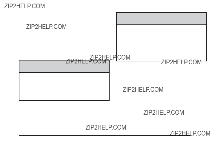
Hill and Mountain Roads
Driving on steep hills or through mountains is different than driving on ???at or rolling terrain. Tips for driving in these conditions include:
???Keep the vehicle serviced and in good shape.
???Check all ???uid levels and brakes, tires, cooling system, and transmission.
???Going down steep or long hills, shift to a lower gear.
{ CAUTION:
If you do not shift down, the brakes could get so hot that they would not work well. You would then have poor braking or even none going down a hill. You could crash. Shift down to let the engine assist the brakes on a steep downhill slope.
{ CAUTION:
Coasting downhill in N (Neutral) or with the ignition off is dangerous. The brakes will have to do all the work of slowing down and they could get so hot that they would not work well. You would then have poor braking or even none going down a hill. You could crash. Always have the engine running and the vehicle in gear when going downhill.
???Stay in your own lane. Do not swing wide or cut across the center of the road. Drive at speeds that let you stay in your own lane.
???Top of hills: Be alert ??? something could be in your lane (stalled car, accident).
???Pay attention to special road signs (falling rocks area, winding roads, long grades, passing or

Winter Driving
Driving on Snow or Ice
Drive carefully when there is snow or ice between the tires and the road, creating less traction or grip. Wet ice can occur at about 32??F (0??C) when freezing rain begins to fall, resulting in even less traction. Avoid driving on wet ice or in freezing rain until roads can be treated with salt or sand.
Drive with caution, whatever the condition. Accelerate gently so traction is not lost. Accelerating too quickly causes the wheels to spin and makes the surface under the tires slick, so there is even less traction.
Try not to break the fragile traction. If you accelerate too fast, the drive wheels will spin and polish the surface under the tires even more.
If the vehicle has the Traction Control System (TCS) on page
page
The Antilock Brake System (ABS) on page
Allow greater following distance on any slippery road and watch for slippery spots. Icy patches can occur on otherwise clear roads in shaded areas. The surface of a curve or an overpass can remain icy when the surrounding roads are clear. Avoid sudden steering maneuvers and braking while on ice.
Turn off cruise control, if equipped, on slippery surfaces.
Blizzard Conditions
Being stuck in snow can be in a serious situation. Stay with the vehicle unless there is help nearby. If possible, use the Roadside Assistance Program on page
To get help and keep everyone in the vehicle safe:
???Turn on the Hazard Warning Flashers on page
???Tie a red cloth to an outside mirror.
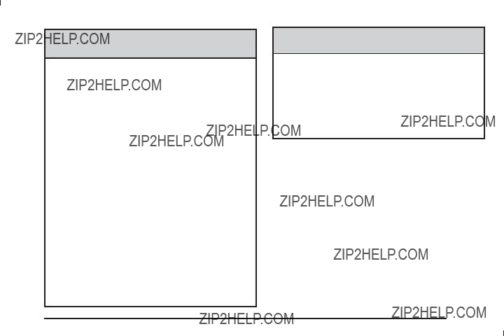
{ CAUTION:
Snow can trap engine exhaust under the vehicle. This may cause exhaust gases to get inside. Engine exhaust contains carbon monoxide (CO) which cannot be seen or smelled. It can cause
unconsciousness and even death.If the vehicle is stuck in the snow:
???Clear away snow from around the base of your vehicle, especially any that is blocking the exhaust pipe.
???Check again from time to time to be sure snow does not collect there.
???Open a window about two inches (5 cm) on the side of the vehicle that is away from the wind to bring in fresh air.
???Fully open the air outlets on or under the instrument panel.
???Adjust the Climate Control system to a setting that circulates the air inside the vehicle and set the fan speed to the highest setting.
See Climate Control System in the Index.
For more information about carbon monoxide, see
Engine Exhaust on page
CAUTION: (Continued)
CAUTION: (Continued)
Snow can trap exhaust gases under your vehicle. This can cause deadly CO (carbon monoxide) gas to get inside. CO could overcome you and kill you. You cannot see it or smell it, so you might not know it is in your vehicle. Clear away snow from around the base of your vehicle, especially any that is blocking the exhaust.
Run the engine for short periods only as needed to keep warm, but be careful.
To save fuel, run the engine for only short periods as needed to warm the vehicle and then shut the engine off and close the window most of the way to save heat. Repeat this until help arrives but only when you feel really uncomfortable from the cold. Moving about to keep warm also helps.
If it takes some time for help to arrive, now and then when you run the engine, push the accelerator pedal slightly so the engine runs faster than the idle speed. This keeps the battery charged to restart
the vehicle and to signal for help with the headlamps. Do this as little as possible to save fuel.

If Your Vehicle is Stuck in Sand, Mud, Ice, or Snow
Slowly and cautiously spin the wheels to free the vehicle when stuck in sand, mud, ice, or snow.
See Rocking Your Vehicle to Get It Out on page
If the vehicle has a traction system, it can often help to free a stuck vehicle. Refer to the vehicle???s traction
system in the Index. If stuck too severely for the traction system to free the vehicle, turn the traction system off and use the rocking method.
{ CAUTION:
If you let your vehicle???s tires spin at high speed, they can explode, and you or others could be injured. The vehicle can overheat, causing an engine compartment ???re or other damage. Spin the wheels as little as possible and avoid going above 35 mph (55 km/h) as shown on the speedometer.
For information about using tire chains on the vehicle, see Tire Chains on page
Rocking Your Vehicle to Get It Out
Turn the steering wheel left and right to clear the area around the front wheels. Turn off any traction system. Shift back and forth between R (Reverse) and a forward gear, or with a manual transmission, between 1 (First) or 2 (Second) and R (Reverse), spinning the wheels as little as possible. To prevent transmission wear, wait until the wheels stop spinning before shifting gears. Release the accelerator pedal while shifting, and press lightly on the accelerator pedal when the transmission is in gear. Slowly spinning the wheels in the forward and reverse directions causes a rocking motion that could free the vehicle. If that does not get the vehicle out after a few tries, it might need to be towed out. If the vehicle does need to be towed out, see Towing Your Vehicle on
page
Loading the Vehicle
It is very important to know how much weight your vehicle can carry. Two labels on your vehicle show how much weight it may properly carry, the Tire and Loading Information label and the Vehicle Certi???cation label.
{ CAUTION:
Do not load the vehicle any heavier than the Gross Vehicle Weight Rating (GVWR), or either the maximum front or rear Gross Axle Weight Rating (GAWR). If you do, parts on the vehicle can break, and it can change the way your vehicle handles. These could cause you to lose control and crash. Also, overloading can shorten the life of the vehicle.

Tire and Loading Information Label
Label Example
A vehicle speci???c Tire and Loading Information label is attached to the vehicle???s center pillar
The tire and loading information label lists the number of occupant seating positions (A), and the maximum vehicle capacity weight (B) in kilograms and pounds. The vehicle capacity weight includes the weight of all occupants, cargo, and all
The Tire and Loading Information label also lists the tire size of the original equipment tires (C) and the recommended cold tire in???ation pressures (D).
For more information on tires and in???ation, see
Tires on page
There is also important loading information on the Certi???cation/Tire label. It tells you the Gross Vehicle Weight Rating (GVWR) and the Gross Axle Weight Rating (GAWR) for the front and rear axles.
See ???Certi???cation/Tire Label??? later in this section.

Steps for Determining Correct Load Limit
1.Locate the statement ???The combined weight of occupants and cargo should never exceed XXX kg or XXX lbs??? on your vehicle???s placard.
2.Determine the combined weight of the driver and passengers that will be riding in your vehicle.
3.Subtract the combined weight of the driver and passengers from XXX kg or XXX lbs.
4.The resulting ???gure equals the available amount of cargo and luggage load capacity. For example, if the ???XXX??? amount equals 1400 lbs and there will be ???ve 150 lb passengers in your vehicle, the amount of
available cargo and luggage load capacity is 650 lbs (1400 ??? 750 (5 x 150) = 650 lbs).
5.Determine the combined weight of luggage and cargo being loaded on the vehicle. That weight may not safely exceed the available cargo and luggage load capacity calculated in Step 4.
6.If your vehicle will be towing a trailer, the load from your trailer will be transferred to your vehicle. Consult this manual to determine how this reduces the available cargo and luggage load capacity for your vehicle.
If your vehicle can tow a trailer, see Towing a Trailer (Automatic Transmission) on page
page

Example 1
Example 2
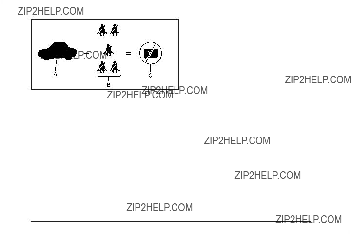
Refer to your vehicle???s tire and loading information label for speci???c information about your vehicle???s maximum vehicle capacity weight and seating positions. The combined weight of the driver, passengers, and cargo should never exceed your vehicle???s maximum vehicle capacity weight.
Example 3

Certi???cation Label
A vehicle speci???c Certi???cation/Tire label is found on the rear edge of the driver???s door, or on the vehicle???s center pillar
The label shows the size of your original tires and the in???ation pressures needed to obtain
the gross weight capacity of your vehicle. This is called the Gross Vehicle Weight Rating (GVWR). The GVWR includes the weight of the vehicle, all occupants, fuel, and cargo.
The Certi???cation/Tire label also tells you the maximum weights for the front and rear axles, called the Gross Axle Weight Rating (GAWR). To ???nd out the actual loads on your front and rear axles, you need to go to a weigh station and weigh your vehicle. Your dealer can help you with this. Be sure to spread out your load equally on both sides of the centerline.
Never exceed the GVWR for your vehicle or the GAWR for either the front or rear axle.
{ CAUTION:
Do not load the vehicle any heavier than the Gross Vehicle Weight Rating (GVWR), or either the maximum front or rear Gross Axle Weight Rating (GAWR). If you do, parts on the vehicle can break, and it can change the way your vehicle handles. These could cause you to lose control and crash. Also, overloading can shorten the life of the vehicle.
Notice: Overloading your vehicle may cause damage. Repairs would not be covered by your warranty. Do not overload your vehicle.

If you put things inside your vehicle ??? like suitcases, tools, packages, or anything else ??? they will go as fast as the vehicle goes. If you have to stop or turn quickly, or if there is a crash, they will keep going.
{ CAUTION:
Things you put inside your vehicle can strike and injure people in a sudden stop or turn, or in a crash.
???Put things in the cargo area of your vehicle. Try to spread the weight evenly.
???Never stack heavier things, like suitcases, inside the vehicle so that some of them are above the tops of the seats.
???Do not leave an unsecured child restraint in your vehicle.
???When you carry something inside the vehicle, secure it whenever you can.
???Do not leave a seat folded down unless you need to.
Towing
Towing Your Vehicle
To avoid damage, the disabled vehicle should be towed with all four wheels off the ground. Consult your dealer/ retailer or a professional towing service if the disabled vehicle must be towed. See Roadside Assistance Program on page
To tow the vehicle behind another vehicle for recreational purposes, such as behind a motorhome, see ???Recreational Vehicle Towing??? following.
Recreational Vehicle Towing
Recreational vehicle towing means towing the vehicle behind another vehicle ??? such as behind a motorhome. The two most common types of recreational vehicle towing are known as dinghy towing and dolly towing. Dinghy towing is towing the vehicle with all four wheels on the ground. Dolly towing is towing the vehicle with two wheels on the ground and two wheels up on a device known as a dolly.

Here are some important things to consider before recreational vehicle towing:
???What is the towing capacity of the towing vehicle? Be sure to read the tow vehicle manufacturer???s recommendations.
???What is the distance that will be travelled? Some vehicles have restrictions on how far and how long they can tow.
???Is the proper towing equipment going to be used? See your dealer/retailer or trailering professional for additional advice and equipment recommendations.
???Is the vehicle ready to be towed? Just as preparing the vehicle for a long trip, make sure the vehicle is prepared to be towed. See Before Leaving on a Long Trip on page
Dinghy Towing
Use the following procedure to dinghy tow the vehicle from the front with all four wheels on the ground:
1.Set the parking brake.
2.Turn the ignition key to ACC/ACCESSORY to unlock the steering wheel.
3.Shift the transmission to N (Neutral).
4.Release the parking brake.

To prevent the battery from draining while the vehicle is being towed, remove the following fuse from the ???oor console fuse block: 8 (Ignition Switch,
more information.
Remember to reinstall the fuse once the destination has been reached.
Notice: If 65 mph (105 km/h) is exceeded while towing the vehicle, it could be damaged. Never exceed 65 mph (105 km/h) while towing the vehicle.
Notice: Towing the vehicle from the rear could damage it. Also, repairs would not be covered by the vehicle warranty. Never have the vehicle towed from the rear.
Dolly Towing
Use the following procedure to dolly tow the vehicle from the front with two wheels on the ground:
1.Put the front wheels on a dolly.
2.Move the shift lever to P (Park).
3.Set the parking brake and then remove the key.
4.Clamp the steering wheel in a
5.Secure the vehicle to the dolly.
6.Release the parking brake.
Towing a Trailer
(Automatic Transmission)
{ CAUTION:
The driver can lose control when pulling a trailer if the correct equipment is not used or the vehicle is not driven properly. For example, if the trailer is too heavy, the brakes may not work well ??? or even at all. The driver and passengers could be seriously injured. The vehicle may also be damaged; the resulting repairs would not be covered by the vehicle warranty. Pull a trailer only if all the steps in this section have been followed. Ask your dealer/ retailer for advice and information about towing a trailer with the vehicle.
The vehicle can tow a trailer if it is equipped with an automatic transmission and the proper trailer towing equipment. If the vehicle is not equipped as stated above, do not tow a trailer. To identify the trailering capacity of the vehicle, read the information in ???Weight of the Trailer??? that appears later in this section.
Trailering is different than just driving the vehicle by itself. Trailering means changes in handling, acceleration, braking, cooling, durability and fuel economy. Successful, safe trailering takes correct equipment, and it has to be used properly.
The following information has many
SS Package
If the vehicle has the SS package, it is neither designed nor intended to tow a trailer.
Pulling A Trailer
Here are some important points:
???There are many different laws, including speed limit restrictions, having to do with trailering. Make sure the rig will be legal, not only where you live but also where you will be driving. A good source for this information can be state or provincial police.
???Do not tow a trailer at all during the ???rst 500 miles (800 km) the new vehicle is driven. The engine, transmission or other parts could be damaged.
???Then, during the ???rst 500 miles (800 km) that a trailer is towed, do not drive over 50 mph (80 km/h) and do not make starts at full throttle. This helps the engine and other parts of the vehicle wear in at the heavier loads.
???Obey speed limit restrictions when towing a trailer. Do not drive faster than the maximum posted speed for trailers, or no more than 55 mph (90 km/h), to save wear on the vehicle???s parts.
???Do not tow when the outside air temperature is above 100??F (38??C).
???Do not tow more than 1,000 miles (1 600 km) per year.
Three important considerations have to do with weight:
???The weight of the trailer
???The weight of the trailer tongue
???The total weight on the vehicle???s tires
Weight of the Trailer
How heavy can a trailer safely be?
It should never weigh more than 1,000 lbs (450 kg). But even that can be too heavy.
It depends on how the rig is used. For example, speed, altitude, road grades, outside temperature and how much the vehicle is used to pull a trailer are all important. It can depend on any special equipment on the vehicle, and the amount of tongue weight the vehicle can carry. See ???Weight of the Trailer Tongue??? later in this section for more information.
Maximum trailer weight is calculated assuming only the driver is in the tow vehicle and it has all the required trailering equipment. The weight of additional optional equipment, passengers and cargo in the tow vehicle must be subtracted from the maximum trailer weight.
Ask your dealer/retailer for our trailering information or advice, or write us at our Customer Assistance Offices. See Customer Assistance Offices on page

Weight of the Trailer Tongue
The tongue load (A) of any trailer is an important weight to measure because it affects the total gross weight of the vehicle. The Gross Vehicle Weight (GVW) includes the curb weight of the vehicle, any cargo carried in it, and the people who will be riding in the vehicle. If there are a lot of options, equipment, passengers or cargo in the vehicle, it will reduce the tongue weight the vehicle can carry, which will also reduce the trailer weight the vehicle can tow.
If towing a trailer, the tongue load must be added to the GVW because the vehicle will be carrying that weight, too. See Loading the Vehicle on page
If using a
Do not exceed the maximum allowable tongue weight for the vehicle. Choose the shortest hitch extension that will position the hitch ball closest to the vehicle. This will help reduce the effect of trailer tongue weight on the rear axle.
After loading the trailer, weigh the trailer and then the tongue, separately, to see if the weights are proper. If they are not, adjustments might be made by moving some items around in the trailer.
Trailering may be limited by the vehicle???s ability to carry tongue weight. Tongue weight cannot cause the vehicle to exceed the GVWR (Gross Vehicle Weight Rating) or the RGAWR (Rear Gross Axle Weight Rating). The effect of additional weight may reduce the trailering capacity more than the total of the additional weight.

Consider the following example:
A vehicle model base weight is 5,500 lbs (2 495 kg); 2,800 lbs (1 270 kg) at the front axle and 2,700 lbs
(1 225 kg) at the rear axle. It has a GVWR of 7,200 lbs (3 266 kg), a RGAWR of 4,000 lbs (1 814 kg) and a GCWR (Gross Combination Weight Rating) of
14,000 lbs (6 350 kg). The trailer rating should be:
Expect tongue weight to be at least 10 percent of trailer weight (850 lbs (386 kg)) and because the weight is applied well behind the rear axle, the effect on the rear axle is greater than just the weight itself, as much as 1.5 times as much. The weight at the rear axle could be 850 lbs (386 kg) X 1.5 = 1,275 lbs (578 kg). Since the rear axle already weighs 2,700 lbs (1 225 kg), adding 1,275 lbs (578 kg) brings the total to 3,975 lbs (1 803 kg). This is very close to, but within the limit for RGAWR as well. The vehicle is set to trailer up to 8,500 lbs
(3 856 kg).
If the vehicle has many options and there is a front seat passenger and two rear seat passengers with some luggage and gear in the vehicle as well. 300 lbs (136 kg) could be added to the front axle weight and 400 lbs
(181 kg) to the rear axle weight. The vehicle now weighs:
Weight is still below 7,200 lbs (3 266 kg) and you might think 700 additional pounds (318 kg) should be subtracted from the trailering capacity to stay within GCWR limits. The maximum trailer would only be 7,800 lbs (3 538 kg). You may go further and think the tongue weight should be limited to less than 1,000 lbs (454 kg) to avoid exceeding GVWR. But the effect on the rear axle must still be considered. Because the rear axle now weighs 3,100 lbs (1 406 kg), 900 lbs (408 kg) can be put on the rear axle without exceeding RGAWR. The effect of tongue weight is about 1.5 times the actual weight. Dividing the 900 lbs (408 kg) by 1.5 leaves only 600 lbs (272 kg) of tongue weight that can be handled. Since tongue weight is usually at least 10 percent of total loaded trailer weight, expect that the largest trailer the vehicle can properly handle is 6,000 lbs (2 721 kg).

It is important that the vehicle does not exceed any of its ratings ??? GCWR, GVWR, RGAWR, Maximum Trailer Rating or Tongue Weight. The only way to be sure it
is not exceeding any of these ratings is to weigh the vehicle and trailer.
Total Weight on the Vehicle???s Tires
Be sure the vehicle???s tires are in???ated to the upper limit for cold tires. These numbers can be found on the
Hitches
It is important to have the correct hitch equipment. Crosswinds, large trucks going by and rough roads are a few reasons why the right hitch is needed.
???The rear bumper on the vehicle is not intended for hitches. Do not attach rental hitches or other
???Will there be any holes in the body of the vehicle after installing a trailer hitch? If there are, then be sure to seal the holes later when the hitch is removed. If the holes are not sealed, deadly carbon monoxide (CO) from exhaust can get into the vehicle. See Engine Exhaust on page
Safety Chains
Always attach chains between the vehicle and the trailer. Cross the safety chains under the tongue of
the trailer to help prevent the tongue from contacting the road if it becomes separated from the hitch. Always leave just enough slack so the rig can turn. Never
allow safety chains to drag on the ground.
Trailer Brakes
A loaded trailer that weighs more than 1,500 lbs (680 kg) needs to have its own brake system that is adequate for the weight of the trailer. Be sure to read and follow the instructions for the trailer brakes so they are installed, adjusted and maintained properly.
Driving with a Trailer
Towing a trailer requires a certain amount of experience. Get to know the rig before setting out for the open road. Get acquainted with the feel of handling and braking with the added weight of the trailer. And always keep in mind that the vehicle you are driving is now longer and not as responsive as the vehicle is by itself.
Before starting, check all trailer hitch parts and attachments, safety chains, electrical connectors, lamps, tires and mirror adjustments. If the trailer has electric brakes, start the vehicle and trailer moving and then apply the trailer brake controller by hand to be sure the brakes are working. This checks
the electrical connection at the same time.

During the trip, check occasionally to be sure that the load is secure, and that the lamps and any trailer brakes are still working.
Following Distance
Stay at least twice as far behind the vehicle ahead as you would when driving the vehicle without a trailer. This can help to avoid situations that require heavy braking and sudden turns.
Passing
More passing distance is needed when towing a trailer. Because the rig is longer, it is necessary to go much farther beyond the passed vehicle before returning to the lane.
Backing Up
Hold the bottom of the steering wheel with one hand. Then, to move the trailer to the left, move that hand to the left. To move the trailer to the right, move your
hand to the right. Always back up slowly and, if possible, have someone guide you.
Making Turns
When turning with a trailer, make wider turns than normal. Do this so the trailer will not strike soft shoulders, curbs, road signs, trees or other objects. Avoid jerky or sudden maneuvers. Signal well in advance.
Turn Signals When Towing a Trailer
The arrows on the instrument panel ???ash whenever signaling a turn or lane change. Properly hooked up, the trailer lamps also ???ash, telling other drivers the vehicle is turning, changing lanes or stopping.
When towing a trailer, the arrows on the instrument panel ???ash for turns even if the bulbs on the trailer are burned out. For this reason you may think other drivers are seeing the signal when they are not. It is important to check occasionally to be sure the trailer bulbs are still working.

Driving on Grades
Notice: Do not tow on steep continuous grades exceeding 6 miles (9.6 km). Extended, higher than normal engine and transmission temperatures may result and damage the vehicle. Frequent stops are very important to allow the engine and transmission to cool.
When towing under severe conditions such as hot ambient temperatures or steep grades, the vehicle may experience more transmission shifting. A COOLING MODE ON message may also appear in the DIC.
This alerts the driver that the shifting mode is in progress and is aiding engine cooling. See DIC Warnings and Messages on page
Reduce speed and shift to a lower gear before starting down a long or steep downgrade. If the transmission is not shifted down, the brakes might have to be used so much that they would get hot and no longer work well.
Pay attention to the engine coolant gage. If the indicator is in the red area, turn off the air conditioning to reduce engine load. See Engine Overheating on page
Parking on Hills
{ CAUTION:
Parking the vehicle on a hill with the trailer attached can be dangerous. If something goes wrong, the rig could start to move. People can be injured, and both the vehicle and the trailer can be damaged. When possible, always park the rig on a ???at surface.
If parking the rig on a hill:
1.Press the brake pedal, but do not shift into P (Park) yet. Turn the wheels into the curb if facing downhill or into traffic if facing uphill.
2.Have someone place chocks under the trailer wheels.
3.When the wheel chocks are in place, release the brake pedal until the chocks absorb the load.
4.Reapply the brake pedal. Then apply the parking brake and shift into P (Park).
5.Release the brake pedal.
Leaving After Parking on a Hill
1.Apply and hold the brake pedal while you:
???start the engine,
???shift into a gear, and
???release the parking brake.
2.Let up on the brake pedal.
3.Drive slowly until the trailer is clear of the chocks.
4.Stop and have someone pick up and store the chocks.
Maintenance When Trailer Towing
The vehicle needs service more often when pulling a trailer. See this manual???s Maintenance Schedule or Index for more information. Things that are especially important in trailer operation are automatic transmission ???uid,
engine oil, axle lubricant, belts, cooling system and brake system. It is a good idea to inspect these before and during the trip.
Check periodically to see that all hitch nuts and bolts are tight.
Engine Cooling When Trailer Towing
The cooling system may temporarily overheat during severe operating conditions. See Engine Overheating on page
Towing a Trailer
(Manual Transmission)
Do not tow a trailer if the vehicle is equipped with a manual transmission.

??? NOTES

Section 5 Service and Appearance Care

Section 5 Service and Appearance Care
Service
For service and parts needs, visit your dealer/retailer. You will receive genuine GM parts and
Genuine GM parts have one of these marks:
Accessories and Modi???cations
When
Damage to vehicle components resulting from the installation or use of
GM Accessories are designed to complement and function with other systems on the vehicle. Your GM dealer/retailer can accessorize the vehicle using genuine GM Accessories. When you go to your GM dealer/retailer and ask for GM Accessories, you will know that
Also, see Adding Equipment to Your

California Proposition 65 Warning
Most motor vehicles, including this one, contain and/or emit chemicals known to the State of California to cause cancer and birth defects or other reproductive harm. Engine exhaust, many parts and systems (including some inside the vehicle), many ???uids, and some component wear
California Perchlorate Materials
Requirements
Certain types of automotive applications, such as airbag initiators, seat belt pretensioners, and lithium batteries contained in remote keyless transmitters, may
contain perchlorate materials. Special handling may be necessary. For additional information, see www.dtsc.ca.gov/hazardouswaste/perchlorate.
Doing Your Own Service Work
{ CAUTION:
You can be injured and the vehicle could be damaged if you try to do service work on a vehicle without knowing enough about it.
???Be sure you have sufficient knowledge, experience, the proper replacement parts, and tools before attempting any vehicle maintenance task.
???Be sure to use the proper nuts, bolts, and other fasteners. English and metric fasteners can be easily confused. If the wrong fasteners are used, parts can later break or fall off. You could be hurt.
If doing some of your own service work, use the proper service manual. It tells you much more about how to service the vehicle than this manual can. To order
the proper service manual, see Service Publications Ordering Information on page
This vehicle has an airbag system. Before attempting to do your own service work, see Servicing Your

Keep a record with all parts receipts and list the mileage and the date of any service work performed. See Maintenance Record on page
Adding Equipment to the Outside of the Vehicle
Things added to the outside of the vehicle can affect the air???ow around it. This can cause wind noise and can affect fuel economy and windshield washer performance. Check with your dealer/retailer before adding equipment to the outside of the vehicle.
Fuel
Use of the recommended fuel is an important part of the proper maintenance of this vehicle. To help keep the engine clean and maintain optimum vehicle performance, we recommend the use of gasoline advertised as TOP TIER Detergent Gasoline.
The 8th digit of the Vehicle Identi???cation Number (VIN) shows the code letter or number that identi???es the vehicle???s engine. The VIN is at the top left of the instrument panel. See Vehicle Identi???cation Number (VIN) on page
If the vehicle has the 2.2L L4 engine (VIN Code B)
or the 2.4L L4 engine (VIN Code V), you can use either unleaded gasoline or ethanol fuel containing up to
85% ethanol (E85). See Fuel E85 (85% Ethanol) on page
See Gasoline Octane on page
Gasoline Octane
If the vehicle has the 2.2L L4 engine (VIN Code B), use regular unleaded gasoline with a posted octane rating of 87 or higher. If the octane rating is less than 87, you might notice an audible knocking noise when you drive, commonly referred to as spark knock. If this occurs, use a gasoline rated at 87 octane or higher as soon as possible. If you are using gasoline rated at
87 octane or higher and you hear heavy knocking, the engine needs service.
If the vehicle has the 2.4L L4 engine (VIN Code V) or the 2.0L L4 engine (VIN Code X), use premium unleaded gasoline with a posted octane rating of 91 or higher. You can also use regular unleaded gasoline rated at
87 octane or higher, but the vehicle???s acceleration could be slightly reduced, and you might notice a slight audible knocking noise, commonly referred to as spark knock.
If the octane is less than 87, you might notice a heavy knocking noise when you drive. If this occurs, use a gasoline rated at 87 octane or higher as soon as possible. Otherwise, you could damage the engine. If you are using gasoline rated at 87 octane or higher and you hear heavy knocking, the engine needs service.

Gasoline Speci???cations
At a minimum, gasoline should meet ASTM speci???cation D 4814 in the United States or
California Fuel
If the vehicle is certi???ed to meet California Emissions Standards, it is designed to operate on fuels that meet California speci???cations. See the underhood emission control label. If this fuel is not available in states adopting California emissions standards, the vehicle will operate satisfactorily on fuels meeting federal speci???cations, but emission control system performance might be affected. The malfunction indicator lamp could turn on and the vehicle might fail a
Additives
To provide cleaner air, all gasolines in the United States are now required to contain additives that help prevent engine and fuel system deposits from forming, allowing the emission control system to work properly. In most cases, you should not have to add anything to the fuel. However, some gasolines contain only the minimum amount of additive required to meet U.S. Environmental Protection Agency regulations. To help keep fuel injectors and intake valves clean, or if the vehicle experiences problems due to dirty injectors or valves, look for gasoline that is advertised as TOP TIER Detergent Gasoline.
For customers who do not use TOP TIER Detergent Gasoline regularly, one bottle of GM Fuel System Treatment PLUS, added to the fuel tank at every engine oil change, can help clean deposits from fuel injectors and intake valves. GM Fuel System Treatment PLUS is the only gasoline additive recommended by General Motors.
Also, your dealer/retailer has additives that will help correct and prevent most

Gasolines containing oxygenates, such as ethers and ethanol, and reformulated gasolines might be available in your area. We recommend that you use these gasolines, if they comply with the speci???cations described earlier. However, E85 (85% ethanol) and other fuels containing more than 10% ethanol must not be used in vehicles that were not designed for those fuels.
Notice: This vehicle was not designed for fuel that contains methanol. Do not use fuel containing methanol. It can corrode metal parts in the fuel system and also damage plastic and rubber parts. That damage would not be covered under the vehicle warranty.
Some gasolines that are not reformulated for low emissions can contain an
of the emission control system could be affected. The malfunction indicator lamp might turn on. If this occurs, return to your dealer/retailer for service.
Fuel E85 (85% Ethanol)
The 8th digit of the Vehicle Identi???cation Number (VIN) shows the code letter or number that identi???es the vehicle???s engine. The VIN is at the top left of the instrument panel. See Vehicle Identi???cation Number (VIN) on page
If your vehicle has the 2.2L L4 engine (VIN Code B)
or the 2.4L L4 engine (VIN Code V), you can use either unleaded gasoline or ethanol fuel containing up to
85% ethanol (E85). See Fuel on page
Only vehicles that have the 2.2L L4 engine (VIN Code B) or the 2.4L L4 engine (VIN Code V) can use 85% ethanol fuel (E85). We encourage the use of E85 in vehicles that are designed to use it. The ethanol in E85 is a ???renewable??? fuel, meaning it is made from renewable sources such as corn and other crops.
Many service stations will not have an 85% ethanol fuel (E85) pump available. The U. S. Department of Energy has an alternative fuels website
(www.eere.energy.gov/afdc/infrastructure/locator.html) that can help you ???nd E85 fuel. Those stations that do have E85 should have a label indicating ethanol content. Do not use the fuel if the ethanol content
is greater than 85%.

At a minimum, E85 should meet ASTM Speci???cation D 5798. By de???nition, this means that fuel labeled E85 will have an ethanol content
between 70% and 85%. Filling the fuel tank with fuel mixtures that do not meet ASTM speci???cations can affect driveability and could cause the malfunction indicator lamp to come on.
To ensure quick starts in the wintertime, the E85 fuel must be formulated properly for your climate according to ASTM speci???cation D 5798. If you have trouble starting on E85, it could be because the E85 fuel is not properly formulated for your climate. If this happens, switching to gasoline or adding gasoline to the fuel tank can improve starting. For good starting and heater efficiency below 32??F (0??C), the fuel mix in the fuel tank should contain no more than 70% ethanol. It is best not to alternate repeatedly between gasoline and E85. If you do switch fuels, it is recommended that you add as much fuel as possible ??? do not add less than three gallons (11 L) when refueling. You should drive the vehicle immediately after refueling for at least seven miles (11 km) to allow the vehicle to adapt to the change in ethanol concentration.
E85 has less energy per gallon than gasoline, so you will need to re???ll the fuel tank more often when using E85 than when you are using gasoline. See Filling the Tank on page
Notice: Some additives are not compatible with E85 fuel and can harm the vehicle???s fuel system. Do not add anything to E85. Damage caused
by additives would not be covered by the vehicle warranty.
Notice: This vehicle was not designed for fuel that contains methanol. Do not use fuel containing methanol. It can corrode metal parts in the fuel system and also damage plastic and rubber parts. That damage would not be covered under the vehicle warranty.
Fuels in Foreign Countries
If you plan on driving in another country outside the United States or Canada, the proper fuel might be hard to ???nd. Never use leaded gasoline or any other fuel not recommended in the previous text on fuel. Costly repairs caused by use of improper fuel would not
be covered by the vehicle warranty.
To check the fuel availability, ask an auto club, or contact a major oil company that does business in the country where you will be driving.
Filling the Tank
{ CAUTION:
Fuel vapor burns violently and a fuel ???re can cause bad injuries. To help avoid injuries to you and others, read and follow all the instructions on the pump island. Turn off the engine when you are refueling. Do not smoke if you are near fuel or refueling the vehicle. Do not use cellular phones. Keep sparks, ???ames, and smoking materials away from fuel. Do not leave the fuel pump unattended when refueling the vehicle. This is against the law in some places. Do not
To open the fuel door, push the rearward center edge in and release and it will open.

The tethered fuel cap is located behind a hinged fuel door on the passenger side of the vehicle. If the vehicle has E85 fuel capability, the fuel cap will be yellow and state that E85 or gasoline can be used. See Fuel E85 (85% Ethanol) on page
To remove the fuel cap, turn it slowly counterclockwise. The fuel cap has a spring in it; if the cap is released too soon, it will spring back to the right.
While refueling, hang the tethered fuel cap from the hook on the fuel door.
{ CAUTION:
Fuel can spray out on you if you open the fuel cap too quickly. If you spill fuel and then something ignites it, you could be badly burned. This spray can happen if the tank is nearly full, and is more likely in hot weather. Open the fuel cap slowly and wait for any hiss noise to stop. Then unscrew the cap all the way.
Be careful not to spill fuel. Do not top off or over???ll
the tank and wait a few seconds after you have ???nished pumping before removing the nozzle. Clean fuel from painted surfaces as soon as possible. See Washing Your Vehicle on page

When replacing the fuel cap, turn it clockwise until it clicks. Make sure the cap is fully installed. The diagnostic system can determine if the fuel cap has been left off or improperly installed. This would allow fuel to evaporate into the atmosphere.
See Malfunction Indicator Lamp on page
The CHECK GAS CAP message displays on the Driver Information Center (DIC) if the fuel cap is not properly installed. See DIC Warnings and Messages on
page
To close the fuel door securely, push the door to the closed position.
{ CAUTION:
If a ???re starts while you are refueling, do not remove the nozzle. Shut off the ???ow of fuel by shutting off the pump or by notifying the station attendant. Leave the area immediately.
Notice: If you need a new fuel cap, be sure to get the right type. Your dealer/retailer can get one
for you. If you get the wrong type, it may not ???t properly. This may cause the malfunction indicator lamp to light and may damage the fuel tank and emissions system. See Malfunction Indicator Lamp on page

Filling a Portable Fuel Container
{ CAUTION:
Never ???ll a portable fuel container while it is in the vehicle. Static electricity discharge from the container can ignite the fuel vapor. You can be badly burned and the vehicle damaged if this occurs. To help avoid injury to you and others:
???Dispense fuel only into approved containers.
???Do not ???ll a container while it is inside a vehicle, in a vehicle???s trunk, pickup bed, or on any surface other than the ground.
???Bring the ???ll nozzle in contact with the inside of the ???ll opening before operating the nozzle. Contact should be maintained until the ???lling is complete.
???Do not smoke while pumping fuel.
???Do not use a cellular phone while pumping fuel.
Checking Things Under
the Hood
{ CAUTION:
An electric fan under the hood can start up and injure you even when the engine is not running. Keep hands, clothing, and tools away from any underhood electric fan.
{ CAUTION:
Things that burn can get on hot engine parts and start a ???re. These include liquids like fuel, oil, coolant, brake ???uid, windshield washer and other ???uids, and plastic or rubber. You or others could be burned. Be careful not to drop or spill things that will burn onto a hot engine.
Hood Release
To open the hood, do the following.
1. Pull the interior hood release lever with this symbol on it. It is located to the left of the instrument panel on the driver???s side of the vehicle.
2. Then go to the front of the vehicle and push the secondary hood release lever to the left. It is located under the front center of the grille.
3.After you have partially lifted the hood, gas struts will automatically take over to lift and hold the hood in the fully open position.
Before closing the hood, be sure all the ???ller caps are on properly. Lower the hood until the lifting force of the struts is reduced, then release the hood
to latch fully. Check to make sure the hood is closed and repeat the process if necessary.

Engine Compartment Overview
When you open the hood on the 2.4L engine (2.2L engine similar), here is what you will see:

A.Windshield Washer Fluid Reservoir. See ???Adding Washer Fluid??? under Windshield Washer Fluid on page
B.Pressure Cap. See Pressure Cap on page
C.Coolant Recovery Tank. See ???Checking Coolant??? under Engine Coolant on page
D.Engine Air Cleaner/Filter. See Engine Air Cleaner/Filter on page
E.Electric Engine Cooling Fan (Out of View). See Cooling System Cooling System on page
F.Engine Oil Fill Cap. See ???When to Add Engine Oil??? under Engine Oil on page
G.Engine Oil Dipstick (Out of View). See ???Checking Engine Oil??? under Engine Oil on page
H.Brake Master Cylinder Reservoir. See Brakes on page
I.Remote Positive (+) Terminal. See Jump Starting on page
J.Engine Compartment Fuse Block. See Engine Compartment Fuse Block on page
K.Remote Negative (???) Terminal (Out of View). See Jump Starting on page

When you open the hood on the 2.0L L4 engine, this is what you will see:

A.Pressure Cap. See Pressure Cap on page
B.Engine Air Cleaner/Filter. See Engine Air Cleaner/Filter on page
C.Windshield Washer Fluid Reservoir. See ???Adding Washer Fluid??? under Windshield Washer Fluid on page
D.Coolant Recovery Tank. See ???Checking Coolant??? under Engine Coolant on page
E.Engine Oil Dipstick. See ???Checking Engine Oil??? under Engine Oil on page
F.Engine Oil Fill Cap. See ???When to Add Engine Oil??? under Engine Oil on page
G.Brake Master Cylinder Reservoir. See ???Brake Fluid??? under Brakes on page
H.Underhood Fuse Block. See Engine Compartment Fuse Block on page
I.Remote Negative (???) Terminal. See Jump Starting on page
J.Remote Positive (+) Terminal. See Jump Starting on page
Engine Oil
Checking Engine Oil
It is a good idea to check the engine oil level at each fuel ???ll. In order to get an accurate reading, the oil must be warm and the vehicle must be on level ground.
The engine oil dipstick handle is a yellow loop. See Engine Compartment Overview on page
1.Turn off the engine and give the oil several minutes to drain back into the oil pan. If this is not done, the oil dipstick might not show the actual level.
2.Pull out the dipstick and clean it with a paper towel or cloth, then push it back in all the way. Remove it again, keeping the tip down, and check the level.

When to Add Engine Oil
If the oil is below the MIN (minimum) mark, add at least one quart/liter of the recommended oil. This section explains what kind of oil to use. For engine oil crankcase capacity, see Capacities and Speci???cations on
page
Notice: Do not add too much oil. If the engine has so much oil that the oil level gets above the upper mark that shows the proper operating range, the engine could be damaged.
See Engine Compartment Overview on page
Add enough oil to put the level somewhere in the proper operating range. Push the dipstick all the way back in when through.

What Kind of Engine Oil to Use
For Vehicles With the 2.2L or 2.4L L4 Engine
Look for three things:
??? GM6094M
Use only an oil that meets GM Standard GM6094M.
??? SAE
SAE
??? American Petroleum Institute (API) starburst symbol
Oils meeting these requirements should have the starburst symbol on the container. This symbol indicates that the oil has been certi???ed by the American Petroleum Institute (API).
Notice: Use only engine oil identi???ed as meeting GM Standard GM6094M and showing the American Petroleum Institute Certi???ed For Gasoline Engines starburst symbol. Failure to use the recommended oil can result in engine damage not covered by the vehicle warranty.

For Vehicles with the 2.0L L4 Engine Only
Look for three things:
??? GM4718M
This vehicle???s engine requires a special oil meeting GM Standard GM4718M, such as Mobil 1?? or equivalent. Oils meeting this standard may be identi???ed as synthetic. However, not all synthetic oils will meet this GM standard. Use only an oil that meets GM Standard GM4718M.
Notice: Using oils that do not have the GM4718M Standard designation can cause engine damage not covered by the vehicle warranty.
??? SAE
SAE
??? American Petroleum Institute (API) starburst symbol
Oils meeting these requirements should have the starburst symbol on the container. This symbol indicates that the oil
has been certi???ed by the American Petroleum Institute (API).
This vehicle???s engine was ???lled at the factory with a synthetic oil meeting all requirements for this vehicle.
Substitute Engine Oil: When adding oil to maintain engine oil level, oil meeting GM Standard GM4718M might not be available. You can add substitute oil designated SAE
at all temperatures. Substitute oil not meeting GM Standard GM4718M should not be used for an
oil change.

Cold Temperature Operation
For Vehicles With the 2.2L or 2.4L L4 Engine
If in an area of extreme cold, where the temperature falls below ???20??F (???29??C), use either an SAE
Oil to Use??? for more information.
Engine Oil Additives/Engine Oil Flushes
Do not add anything to the oil. The recommended oils with the starburst symbol that meet GM standards are all that is needed for good performance and engine protection.
Engine oil system ???ushes are not recommended and could cause engine damage not covered by the vehicle warranty.
Engine Oil Life System
When to Change Engine Oil
This vehicle has the Engine Oil Life System, a computer system that indicates when to change the engine oil and ???lter. This is based on engine revolutions and engine temperature, and not on mileage. Based on driving conditions, the mileage at which an oil change is indicated can vary considerably. For the oil life system to work properly, the system must be reset every time the oil is changed.
When the system has calculated that oil life has been diminished, it indicates that an oil change is necessary. A CHANGE OIL SOON message comes on. See DIC Warnings and Messages on page
If the system is ever reset accidentally, the oil must be changed at 3,000 miles (5 000 km) since the last oil change. Remember to reset the oil life system whenever the oil is changed.

How to Reset the Engine Oil Life System
The Engine Oil Life System calculates when to change your engine oil and ???lter based on vehicle use. Whenever the oil is changed, reset the system so it can calculate when the next oil change is required. If a situation occurs where the oil is changed prior to a CHANGE OIL SOON message being turned on, reset the system.
After changing the engine oil, the system must be reset:
1.Turn the ignition to ON/RUN, with the engine off.
2.Press the information and reset buttons on the Driver Information Center (DIC) at the same time to enter the personalization menu. See DIC Vehicle Personalization on page
3.Press the information button to scroll through the available personalization menu modes until the DIC display shows
4.Press and hold the reset button until the DIC display shows ACKNOWLEDGED. This will tell you the system has been reset.
5.Turn the key to LOCK/OFF.
For vehicles with the 2.2L (VIN code V) or 2.4L (VIN code B) engines, you can also reset the system
as follows:
1.Turn the ignition key to ON/RUN with the engine off.
2.Fully press and release the accelerator pedal slowly three times within ???ve seconds.
3.Turn the key to LOCK/OFF, then start the engine.
If the CHANGE OIL SOON message comes back
on when the vehicle is started, the engine oil life system has not reset. Repeat the reset procedure.
What to Do with Used Oil
Used engine oil contains certain elements that can be unhealthy for your skin and could even cause cancer. Do not let used oil stay on your skin for very long. Clean your skin and nails with soap and water, or a good hand cleaner. Wash or properly dispose of clothing or rags containing used engine oil. See the manufacturer???s warnings about the use and disposal of oil products.
Used oil can be a threat to the environment. If you change your own oil, be sure to drain all the oil from the ???lter before disposal. Never dispose of oil by putting it in the trash, pouring it on the ground, into sewers, or into streams or bodies of water. Recycle it by taking it to a place that collects used oil.
Engine Air Cleaner/Filter
When to Inspect the Engine Air Cleaner/Filter
Inspect the air cleaner/???lter at the Maintenance II intervals and replace it at the ???rst oil change after each 50,000 mile (80 000 km) interval. See Scheduled Maintenance on page
at each engine oil change. The 2.0L engine inspect at each oil change. Replace ???lter if appears dusty or dirty.
How to Inspect the Engine Air Cleaner/Filter (2.2L and 2.4L Engines)
See Engine Compartment Overview on page
To inspect the air cleaner/???lter remove the ???lter from the vehicle and lightly shake the ???lter to release loose dust and dirt. If the ???lter remains caked with dirt, a new ???lter is required. Never use compressed air to clean the ???lter.
Because this operation can be a little difficult, you may choose to have this done at the dealer/retailer service department.

To inspect or replace the ???lter, do the following:
1.Disconnect the Mass Air Flow sensor, PCV hose, and both ducts.
2.Pull the entire system from the top of the engine.
3.Turn the system over and place it on a soft,
4.Remove the screws that hold the housing and cover together and lift off the housing.
5.Inspect or replace the engine air cleaner/???lter.
6.Reverse the steps to reinstall the system. Be sure to reinstall the housing tightly.
How to Inspect the Engine Air Cleaner/Filter (2.0L Engine Only)
See Engine Compartment Overview on page
To inspect the air cleaner/???lter remove the ???lter from the vehicle and lightly shake the ???lter to release loose dust and dirt. If the ???lter remains caked with dirt, a new ???lter is required. Never use compressed air to clean the ???lter.
Because this operation can be a little difficult, you may choose to have this done at the dealer/retailer service department.

To inspect or replace the ???lter, do the following:
1.Remove the screws that hold the housing and cover together and lift off the cover.
2.Inspect or replace the engine air cleaner/???lter.
3.Reverse the steps to reinstall the system. Be sure to reinstall the housing tightly.
{CAUTION:
Operating the engine with the air cleaner/???lter off can cause you or others to be burned. The air cleaner not only cleans the air; it helps to stop ???ames if the engine back???res. If it is not there and the engine back???res, you could be burned. Do not drive with it off, and be careful working on the engine with the air cleaner/???lter off.
Notice: If the air cleaner/???lter is off, a back???re can cause a damaging engine ???re. And, dirt can easily get into the engine, which will damage it. Always have the air cleaner/???lter in place when you are driving.
Automatic Transmission Fluid
It is not necessary to check the transmission ???uid level. A transmission ???uid leak is the only reason for ???uid loss. If a leak occurs, take your vehicle to a dealer/retailer and have it repaired as soon as possible.
Change the ???uid and ???lter at the intervals listed in the Maintenance Schedule. See Scheduled Maintenance on page
in Recommended Fluids and Lubricants on page
Notice: Use of the incorrect automatic transmission ???uid may damage the vehicle, and the damages may not be covered by the vehicle???s warranty. Always use the automatic transmission ???uid listed in
Recommended Fluids and Lubricants on page

Manual Transmission Fluid
It is not necessary to check the manual transmission ???uid level. A transmission ???uid leak is the only reason for ???uid loss. If a leak occurs, take the vehicle to a dealer/retailer for service. Have it repaired as soon as possible. You may also have the ???uid level checked by your dealer/ retailer when the oil is changed. See Recommended Fluids and Lubricants on page
to use.
Hydraulic Clutch
The hydraulic clutch linkage in your vehicle is
See Brakes on page
Cooling System
The Cooling System allows the engine to maintain the correct working temperature.
A.Pressure Cap
B.Coolant Recovery Tank
C.Electric Engine Cooling Fan

{ CAUTION:
An electric engine cooling fan under the hood can start up even when the engine is not running and can cause injury. Keep hands, clothing, and tools away from any underhood electric fan.
{ CAUTION:
Heater and radiator hoses, and other engine parts, can be very hot. Do not touch them. If you do, you can be burned.
Do not run the engine if there is a leak. If you run the engine, it could lose all coolant. That could cause an engine ???re, and you could be burned. Get any leak ???xed before you drive the vehicle.
Notice: Using coolant other than
Engine Coolant
The cooling system in the vehicle is ???lled with
The following explains the cooling system and how to check and add coolant when it is low. If there is a problem with engine overheating, see Engine Overheating on page

What to Use
{ CAUTION:
Adding only plain water to the cooling system can be dangerous. Plain water, or some other liquid such as alcohol, can boil before the proper coolant mixture will. The vehicle???s coolant warning system is set for the proper coolant mixture. With plain water or the wrong mixture, the engine could get too hot but you would not get the overheat warning. The engine could catch ???re and you or others could be burned. Use a 50/50 mixture of clean, drinkable water and
Use a 50/50 mixture of clean, drinkable water and
???Gives freezing protection down to ???34??F (???37??C), outside temperature.
???Gives boiling protection up to 265??F (129??C), engine temperature.
???Protects against rust and corrosion.
???Will not damage aluminum parts.
???Helps keep the proper engine temperature.
Notice: If an improper coolant mixture is used, the engine could overheat and be badly damaged. The repair cost would not be covered by the vehicle warranty. Too much water in the mixture can freeze and crack the engine, radiator, heater core, and other parts.
Notice: If extra inhibitors and/or additives are used in the vehicle???s cooling system, the vehicle could be damaged. Use only the proper mixture of the engine coolant listed in this manual for the cooling system. See Recommended Fluids and Lubricants on
page

Checking Coolant
The vehicle must be on a level surface when checking the coolant level.
The coolant recovery tank cap has this symbol on it. The tank is located in
the engine compartment toward the front of the engine on the passenger???s side of the vehicle.
See Engine Compartment Overview on page
Check to see if coolant is visible in the coolant recovery tank. If the coolant inside the coolant recovery tank is boiling, do not do anything else until it cools down. If coolant is visible but the coolant level is not at or above the COLD FILL mark, add a 50/50 mixture of clean, drinkable water and
When the engine is cold, the coolant level should be at the COLD FILL (A) line or a little higher. The COLD FILL line is near the bottom of the tank and sticks out from the rear of the tank.
When the engine is cold, the coolant level should be at or above the COLD FILL line. If it is not, you may have a leak in the cooling system.
How to Add Coolant to the Cooling System
{ CAUTION:
You can be burned if you spill coolant on hot engine parts. Coolant contains ethylene glycol and it will burn if the engine parts are hot enough. Do not spill coolant on a hot engine.
Notice: This vehicle has a speci???c coolant ???ll procedure. Failure to follow this procedure could cause the engine to overheat and be severely damaged.
{ CAUTION:
An electric engine cooling fan under the hood can start up even when the engine is not running and can cause injury. Keep hands, clothing, and tools away from any underhood electric fan.
{ CAUTION:
Steam and scalding liquids from a hot cooling system can blow out and burn you badly. They are under pressure, and if you turn the surge tank pressure cap ??? even a little ??? they can come
out at high speed. Never turn the cap when the cooling system, including the surge tank pressure cap, is hot. Wait for the cooling system and surge tank pressure cap to cool if you ever have to turn the pressure cap.

If no coolant is visible in the coolant recovery tank, add coolant at the pressure cap as follows:
1. Remove the pressure cap when the cooling system, including
the pressure cap and upper radiator hose, is no longer hot.
Turn the pressure cap slowly counterclockwise.
If you hear a hiss, wait for that to stop. A hiss means there is still some pressure left to be vented.
2.Then keep turning the pressure cap and remove it.
3.Add the proper
4.Rinse or wipe any spilled coolant from the engine and the compartment.
5.Then ???ll the coolant recovery tank to the COLD FILL (A) line.
6.Put the cap back on the coolant recovery tank, but leave the pressure cap off.
7.Start the engine and let it run until you can feel the upper radiator hose getting hot. Watch out for the engine cooling fan.

8.By this time, the coolant level inside the radiator
???ller port may be lower. If the level is lower, add more of the proper
9.Then replace the pressure cap. At any time during this procedure, if coolant begins to ???ow out of the ???ll port, reinstall the pressure cap. Be sure the pressure cap is
10.When the engine has cooled, check the coolant in the coolant recovery tank. The level in the coolant recovery tank should be at the COLD FILL line when the engine is cold.
Pressure Cap
Notice: If the pressure cap is not tightly installed, coolant loss and possible engine damage may occur. Be sure the cap is properly and tightly secured.
See Engine Compartment Overview on page
Engine Overheating
The vehicle has several indicators to warn of engine overheating.
You will ???nd a coolant temperature warning light and a coolant temperature gage on your vehicle???s instrument panel. See Engine Coolant Temperature Warning Light on page
You may decide not to lift the hood when this warning appears, but instead get service help right away.
See Roadside Assistance Program on page
If you do decide to lift the hood, make sure the vehicle is parked on a level surface.
Then check to see if the engine cooling fans are running. If the engine is overheating, both fans should be running. If they are not, do not continue to run
the engine and have the vehicle serviced.
Notice: Engine damage from running the engine without coolant is not covered by the warranty.
Notice: If the engine catches ???re because of being driven with no coolant, your vehicle can be badly damaged. The costly repairs would not be covered by the vehicle warranty.
If Steam Is Coming From The Engine
Compartment
{ CAUTION:
Steam from an overheated engine can burn you badly, even if you just open the hood. Stay away from the engine if you see or hear steam coming from it. Just turn it off and get everyone away from the vehicle until it cools down. Wait until there is no sign of steam or coolant before you open the hood.
If you keep driving when your engine is overheated, the liquids in it can catch ???re. You or others could be badly burned. Stop your engine if it overheats, and get out of the vehicle until the engine is cool.
If No Steam Is Coming From The
Engine Compartment
If an engine overheat warning is displayed but no steam can be seen or heard, the problem may not be too serious. Sometimes the engine can get a little too hot when the vehicle:
???Climbs a long hill on a hot day.
???Stops after
???Idles for long periods in traffic.
???Tows a trailer.
If the overheat warning is displayed with no sign of steam:
1.Turn the air off.
2.Turn the heater on to the highest temperature and to the highest fan speed. Open the windows as necessary.
3.In heavy traffic, let the engine idle in N (Neutral) while stopped. If it is safe to do so, pull off the road, shift to P (Park) or N (Neutral) and let
the engine idle.

If the temperature overheat gage is no longer in the overheat zone or an overheat warning no longer displays, the vehicle can be driven. Continue to drive the vehicle slow for about 10 minutes. Keep a safe vehicle distance from the car in front of you. If the warning does not come back on, continue to drive normally.
If the warning continues, pull over, stop, and park the vehicle right away.
If there is no sign of steam, idle the engine for three minutes while parked. If the warning is still displayed, turn off the engine until it cools down.
Windshield Washer Fluid
What to Use
When you need windshield washer ???uid, be sure to read the manufacturer???s instructions before use. If you will be operating your vehicle in an area where the temperature may fall below freezing, use a ???uid that has sufficient protection against freezing.
Adding Washer Fluid
Open the cap with the washer symbol on it. Add washer ???uid until the tank is full. See Engine Compartment Overview on page
Notice:
???When using concentrated washer ???uid, follow the manufacturer???s instructions for adding water.
???Do not mix water with
???Fill the washer ???uid tank only
???Do not use engine coolant (antifreeze) in your windshield washer. It can damage the vehicle???s windshield washer system and paint.

Brakes
Brake Fluid
The brake master cylinder and, on manual transmission vehicles, the clutch hydraulic system use the same reservoir. See Engine Compartment Overview on
page
There are only two reasons why the brake ???uid level in the reservoir might go down:
???The brake ???uid level goes down because of normal brake lining wear. When new linings are installed, the ???uid level goes back up.
???A ???uid leak in the brake and/or clutch hydraulic system can also cause a low ???uid level. Have the brake and/or clutch hydraulic system ???xed, since a leak means that sooner or later the brakes and/or clutch will not work well.
Do not top off the brake/clutch ???uid. Adding ???uid does not correct a leak. If ???uid is added when the brake linings are worn, there will be too much ???uid when new brake linings are installed. Add or remove ???uid, as necessary, only when work is done on the brake/clutch hydraulic system.
{ CAUTION:
If too much brake ???uid is added, it can spill on the engine and burn, if the engine is hot enough. You or others could be burned, and the vehicle could be damaged. Add brake ???uid only when work is done on the brake and/or clutch hydraulic system.
When the brake ???uid falls to a low level, the brake warning light comes on. See Brake System Warning Light on page

What to Add
Use only new DOT 3 brake ???uid from a sealed container. See Recommended Fluids and Lubricants on page
Always clean the brake ???uid reservoir cap and the area around the cap before removing it. This helps keep dirt from entering the reservoir.
{ CAUTION:
With the wrong kind of ???uid in the brake or clutch hydraulic system, the brakes or clutch might not work well. This could cause a crash. Always use the proper brake ???uid.
Notice:
???Using the wrong ???uid can badly damage brake or clutch hydraulic system parts. For example, just a few drops of
as engine oil, in the brake or clutch hydraulic system can damage brake or clutch hydraulic system parts so badly that they will have
to be replaced. Do not let someone put in the wrong kind of ???uid.
???If brake ???uid is spilled on the vehicle???s painted surfaces, the paint ???nish can be damaged.
Be careful not to spill brake ???uid on the vehicle. If you do, wash it off immediately. See Washing Your Vehicle on page

Brake Wear
This vehicle has front disc brakes and could have rear drum brakes or rear disc brakes.
Disc brake pads have
{ CAUTION:
The brake wear warning sound means that soon the brakes will not work well. That could lead to an accident. When the brake wear warning sound is heard, have the vehicle serviced.
Notice: Continuing to drive with
Some driving conditions or climates can cause a brake squeal when the brakes are ???rst applied or lightly applied. This does not mean something is wrong with the brakes.
Properly torqued wheel nuts are necessary to help prevent brake pulsation. When tires are rotated, inspect brake pads for wear and evenly tighten wheel nuts in the proper sequence to torque speci???cations in
Capacities and Speci???cations on page
If the vehicle has rear drum brakes, they do not have wear indicators, but if a rear brake rubbing noise is heard, have the rear brake linings inspected immediately. Rear brake drums should be removed and inspected each time the tires are removed for rotation or changing. When the front brake pads are replaced, have the rear brakes inspected, too.
Brake linings should always be replaced as complete axle sets.
Brake Pedal Travel
See your dealer/retailer if the brake pedal does not return to normal height, or if there is a rapid increase in pedal travel. This could be a sign that brake service might be required.
Brake Adjustment
Every time the brakes are applied, with or without the vehicle moving, the brakes adjust for wear.

Replacing Brake System Parts
The braking system on a vehicle is complex. Its many parts have to be of top quality and work well together if the vehicle is to have really good braking. The vehicle was designed and tested with
Battery
Your vehicle has a maintenance free battery. When it is time for a new battery, see your dealer/retailer for
one that has the replacement number shown on the original battery???s label.
The battery is located in the cargo area. Access to the battery is not necessary to jump start the vehicle.
See Jump Starting on page
Warning: Battery posts, terminals, and related accessories contain lead and lead compounds, chemicals known to the State of California to cause cancer and reproductive harm. Wash hands after handling.
Vehicle Storage
{ CAUTION:
Batteries have acid that can burn you and gas that can explode. You can be badly hurt if you are not careful. See Jump Starting on page
Infrequent Usage: If the vehicle is driven infrequently, remove the black, negative (???) cable from the battery. This helps keep the battery from running down.
Extended Storage: For extended storage of the vehicle, remove the black, negative (???) cable from the battery or use a battery trickle charger. This helps maintain the charge of the battery over an extended period of time.
Jump Starting
If the vehicle???s battery has run down, you may want to use another vehicle and some jumper cables to start the vehicle. Be sure to use the following steps to do it safely.
{ CAUTION:
Batteries can hurt you. They can be dangerous because:
???They contain acid that can burn you.
???They contain gas that can explode or ignite.
???They contain enough electricity to burn you.
If you do not follow these steps exactly, some or all of these things can hurt you.
Notice: Ignoring these steps could result in costly damage to the vehicle that would not be covered by the warranty.
Trying to start the vehicle by pushing or pulling it will not work, and it could damage the vehicle.
1.Check the other vehicle. It must have a
Notice: If the other vehicle???s system is not a
2.Get the vehicles close enough so the jumper cables can reach, but be sure the vehicles are not touching each other. If they are, it could cause a ground connection you do not want. You would not be able to start the vehicle, and the bad grounding could damage the electrical systems.
To avoid the possibility of the vehicles rolling, set the parking brake ???rmly on both vehicles involved in the jump start procedure. Put an automatic transmission in P (Park) or a manual transmission in N (Neutral) before setting the parking brake.

Notice: If you leave the radio or other accessories on during the jump starting procedure, they could be damaged. The repairs would not be covered by the warranty. Always turn off the radio and other accessories when jump starting the vehicle.
3.Turn off the ignition on both vehicles. Unplug unnecessary accessories plugged into the cigarette lighter or the accessory power outlet. Turn off
the radio and all lamps that are not needed.
This will avoid sparks and help save both batteries. And it could save the radio!
4.Open the hood on the other vehicle and locate the positive (+) and negative (???) terminal locations on that vehicle.
You will not see the battery of your vehicle under the hood. It is located in the rear cargo area. You will not need to access your battery for jump
starting. The vehicle has a remote positive (+) and a remote negative (???) jump starting terminal.
Locate the remote positive terminal which is located under a red tethered cap on the engine compartment fuse block. Remove the cap to access the terminal.
Do not remove fuse block cover to jump start the vehicle.

Locate the remote negative (???) ground terminal, marked GND (???), which is located at the front of the engine compartment on the driver side of the vehicle.
See Engine Compartment Overview on page
{ CAUTION:
An electric fan can start up even when the engine is not running and can injure you. Keep hands, clothing and tools away from any underhood electric fan.
{ CAUTION:
Using a match near a battery can cause battery gas to explode. People have been hurt doing this, and some have been blinded. Use a ???ashlight if you need more light.
Be sure the battery has enough water. You do not need to add water to the battery installed in your new vehicle. But if a battery has ???ller caps, be sure the right amount of ???uid is there. If it is low, add water to take care of that ???rst. If you don???t, explosive gas could be present.
Battery ???uid contains acid that can burn you. Do not get it on you. If you accidentally get it in your eyes or on your skin, ???ush the place with water and get medical help immediately.

{ CAUTION:
Fans or other moving engine parts can injure you badly. Keep your hands away from moving parts once the engine is running.
5.Check that the jumper cables do not have loose or missing insulation. If they do, you could get a shock. The vehicles could be damaged too.
Before you connect the cables, here are some basic things you should know. Positive (+) will go to
positive (+) or to a remote positive (+) terminal if the vehicle has one. Negative (???) will go to a heavy,
unpainted metal engine part or to a remote negative (???) terminal if the vehicle has one.
Do not connect positive (+) to negative (???) or you will get a short that would damage the battery
and maybe other parts too. And do not connect the negative (???) cable to the negative (???) terminal on the dead battery because this can cause sparks.
6.Connect the red positive (+) cable to the positive (+) terminal location on the vehicle with the dead battery. Use a remote positive (+) terminal if the vehicle
has one.
7.Do not let the other end touch metal. Connect it to the positive (+) terminal of the good battery. Use a remote positive (+) terminal if the vehicle has one.
8.Now connect the black negative (???) cable to the negative (???) terminal of the good battery. Use a remote negative (???) terminal if the vehicle has one.
Do not let the other end touch anything until the next step. The other end of the negative (???) cable does not go to the dead battery. It goes to a
heavy, unpainted metal engine part or to a remote negative (???) terminal on the vehicle with the dead battery.
9.Connect the other end of the negative (???) cable to the negative (???) terminal location on the vehicle
with the dead battery. Your vehicle has a remote negative (???) ground terminal marked GND (???).
10.Now start the vehicle with the good battery and run the engine for a while.
11.Try to start the vehicle that had the dead battery. If it will not start after a few tries, it probably needs service.
Notice: If the jumper cables are connected or removed in the wrong order, electrical shorting may occur and damage the vehicle. The repairs would not be covered by the vehicle warranty. Always connect and remove the jumper cables in the correct order, making sure that the cables do not touch each other or other metal.
Jumper Cable Removal
A.Heavy, Unpainted Metal Engine Part or Remote Negative (???) Terminal (GND)
B.Good Battery or Remote Positive (+) and Remote Negative (???) Terminals
C.Dead Battery or Remote Positive (+) Terminal
To disconnect the jumper cables from both vehicles:
1.Disconnect the black negative (???) cable from the vehicle that had the dead battery.
2.Disconnect the black negative (???) cable from the vehicle with the good battery.
3.Disconnect the red positive (+) cable from the vehicle with the good battery.
4.Disconnect the red positive (+) cable from the other vehicle.
5.Return the positive (+) terminal cover to its original position.

Headlamp Aiming
The vehicle has a visual optical headlamp aiming system. The aim has been preset at the factory and should need no further adjustment.
However, if the vehicle is damaged in a crash, the headlamp aim may be affected and adjustment may be necessary.
If oncoming vehicles ???ash their high beams at you, this may also mean the vertical aim needs to be adjusted.
It is recommended that the vehicle is taken to your dealer/retailer for service if the headlamps need to be
The vehicle should:
???Be placed so the headlamps are 25 ft. (7.6 m) from a light colored wall.
???Have all four tires on a level surface which is level all the way to the wall.
???Be placed so it is perpendicular to the wall or other ???at surface.
???Not have any snow, ice, or mud on it.
???Be fully assembled and all other work stopped while headlamp aiming is being performed.
???Normally loaded with a full tank of fuel and one person or 160 lbs (75 kg) sitting on the driver seat.
???Have all tires properly in???ated.
???Have the spare tire is in its original location in the vehicle.
Headlamp aiming is done with the vehicle???s