LIMITED WARRANTY
This warranty only applies to units purchased from an authorized retailer. Manufacturer warrants to the original consumer-purchaser only that this product shall be free from defects in workmanship and materials after correct assembly and under normal and reasonable home use for the periods indicated below beginning on the date of purchase*. The manufacturer reserves the right to require that defective parts be returned, postage and or freight pre-paid by the consumer for review and examination.
*Note: A dated sales reciept WILL be required for warranty service.
The original consumer-purchaser will be responsible for all shipping charges for parts replaced under the terms of this limited warranty.
This limited warranty is applicable in the United States and Canada only, is only available to the original owner of the product and is not transferable.
Manufacturer requires proof of your date of purchase. Therefore, you should retain your sales slip or invoice. Registering your product is not a substitute for proof of purchase and the manufacturer is not responsible for or required to retain proof of purchase records.
This limited warranty applies to the functionality of the product ONLY and does not cover cosmetic issues such as scratches, dents, corrosions or discoloring by heat, abrasive and chemical cleaners or any tools used in the assembly or installation of the appliance, surface rust, or the discoloration of stainless steel surfaces. RUST is not considered a manufacturing or materials defect.
This limited warranty will not reimburse you for the cost of any inconvenience, food, personal injury or property damage.
ITEMS MANUFACTURER WILL NOT PAY FOR:
1.Shipping cost, standard or expedited, for warranty and replacement parts
2.Service calls to your home.
3.Repairs when your product is used for other than normal, single-family household or residential use.
4.Damage, failures, or operating difficulties resulting from accident, alteration, careless handling, misuse, abuse, fire, flood,
acts of God, improper installation or maintenance, installation not in accordance with electrical or plumbing codes, or use of products not approved by the manufacturer.
5. Any food loss due to product failures or operating difficulties.
6. Replacement parts or repair labor costs for units operated outside the United States or Canada. 7. Pickup and delivery of your product.
8. Repairs to parts or systems resulting from unauthorized modifications made to the product. 9. The removal and/or reinstallation of your product.
DISCLAIMER OF IMPLIED WARRANTIES and LIMITATION OF REMEDIES
Repair or replacement of defective parts is your exclusive remedy under the terms of this limited warranty. In the event of parts availability issues, the manufacturer reserves the right to substitute like or similar parts that are equally functional.
Manufacturer will not be responsible for any consequential or incidental damages arising from the breach of either this limited warranty or any applicable implied warranty, or for failure or damage resulting from acts of God, improper care and maintenance, grease fire, accident, alteration,
replacement of parts by anyone other than Manufacturer, misuse, transportation, commercial use, abuse, hostile environments (inclement weather,
acts of nature, animal tampering), improper installation or installation not in accordance with local codes or printed manufacturer instructions.
THIS LIMITED WARRANTY IS THE SOLE EXPRESS WARRANTY GIVEN BY THE MANUFACTURER. NO PRODUCT PERFORMANCE
SPECIFICATION OR DESCRIPTION WHEREVER APPEARING IS WARRANTED BY MANUFACTURER EXCEPT TO THE EXTENT SET
FORTH IN THIS LIMITED WARRANTY. ANY IMPLIED WARRANTY PROTECTION ARISING UNDER THE LAWS OF ANY STATE,
INCLUDING IMPLIED WARRANTY OF MERCHANTABILITY OR FITNESS FOR A PARTICULAR PURPOSE OR USE, IS HEREBY
LIMITED IN DURATION TO THE DURATION OF THIS LIMITED WARRANTY.
Neither dealers nor the retail establishment selling this product has any authority to make any additional warranties or to promise remedies
in addition to or inconsistent with those stated above. Manufacturer's maximum liability, in any event, shall not exceed the purchase price of the product paid by the original consumer.
NOTE: Some states do not allow an exclusion or limitation of incidental or consequential damages, so some of the above limitations or exclusions may not apply to you. This limited warranty gives you specific legal rights as set foth herein. You may also have other rights which vary from state to state. In the state of California only, if refinishing or replacement of the product is not commercially practicable, the retailer selling this product or the Manufacturer will refund the purchase price paid for the product, less the amount directly attributable to use by the original consumer-purchaser prior to discovery of the nonconformity. In addition, in the state of California only, you may take the product to the retail establishment selling this product in order to obtain performance under this limited warranty.
If you wish to obtain performance of any obligation under this limited warranty, you should
write to:
Consumer Relations
P. O. Box 1240
Columbus, GA 31902-1240
Consumer returns will not be accepted unless a valid Return Authorization is first acquired. Authorized returns are clearly marked on the outside of the package with an RA number and the package is shipped freight/postage pre-paid. Consumer returns that do not meet these standards will be refused.

 CAUTION:
 WARNING:
 CAUTION:
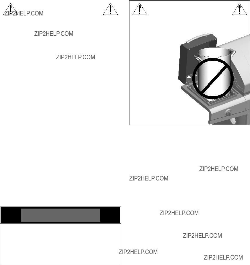
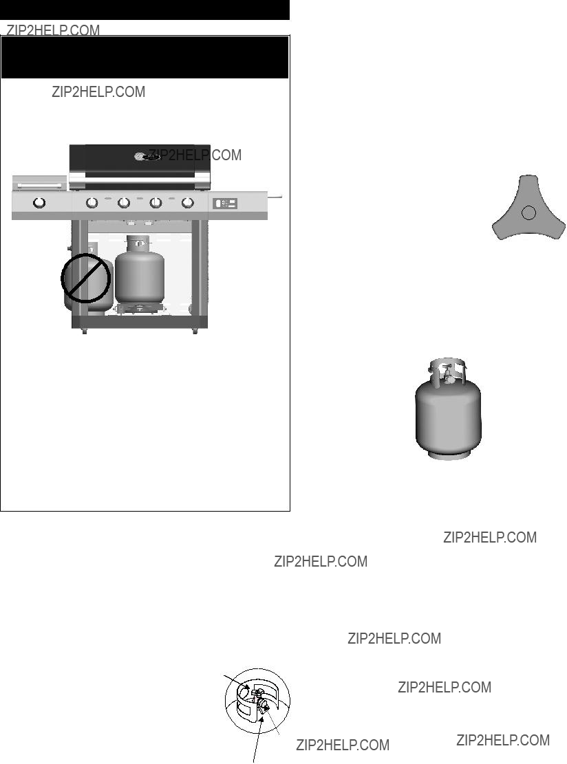


 OFF all gas burner control valves.
 position.
 OFF, wait 5 minutes, and repeat the lighting procedure.


 position.
 position. Be sure burner lights and stays lit.
 to
to . You should see a smaller flame in
  position than seen on
  . Perform burner flame check on sideburner, also. Always check flame prior to each use. If only low flame is seen refer to "Sudden drop or low flame" in the


 Extension cord, for out door use


 B
B
 II
II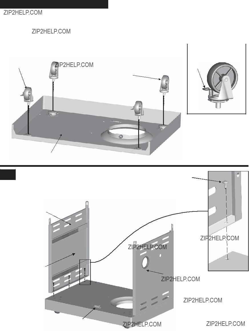

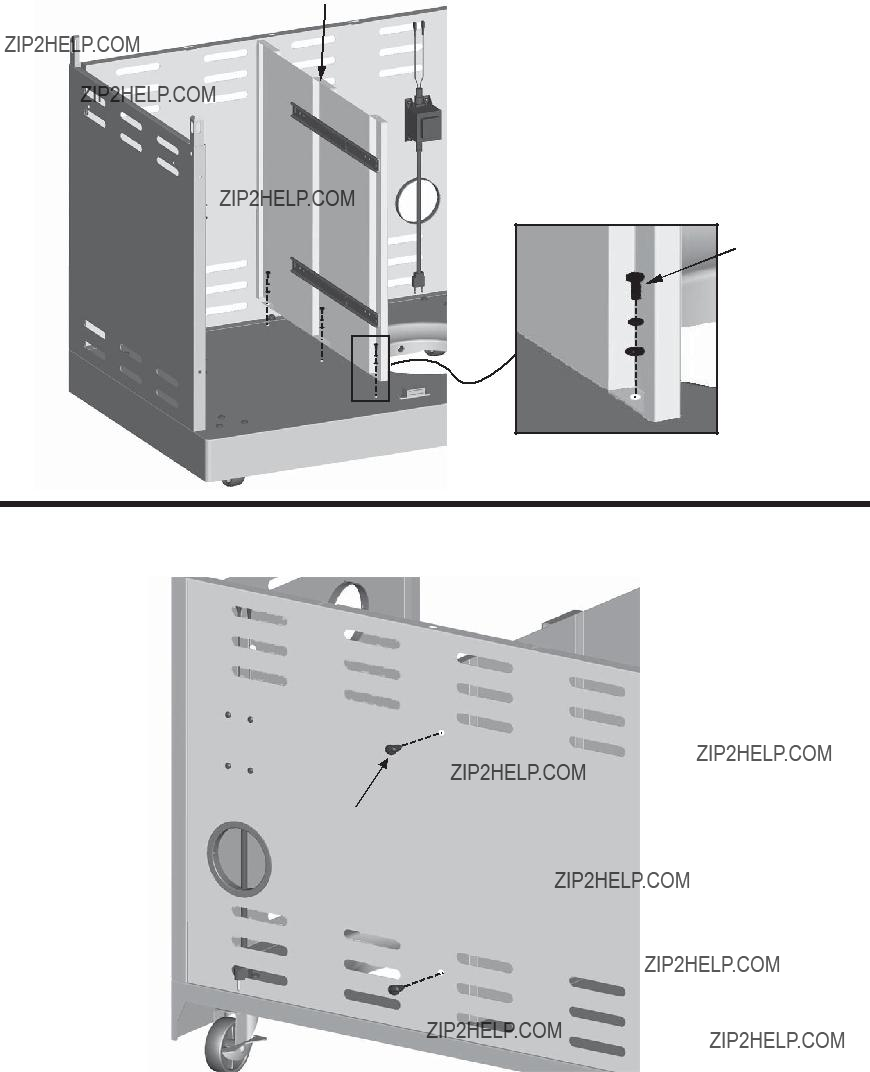
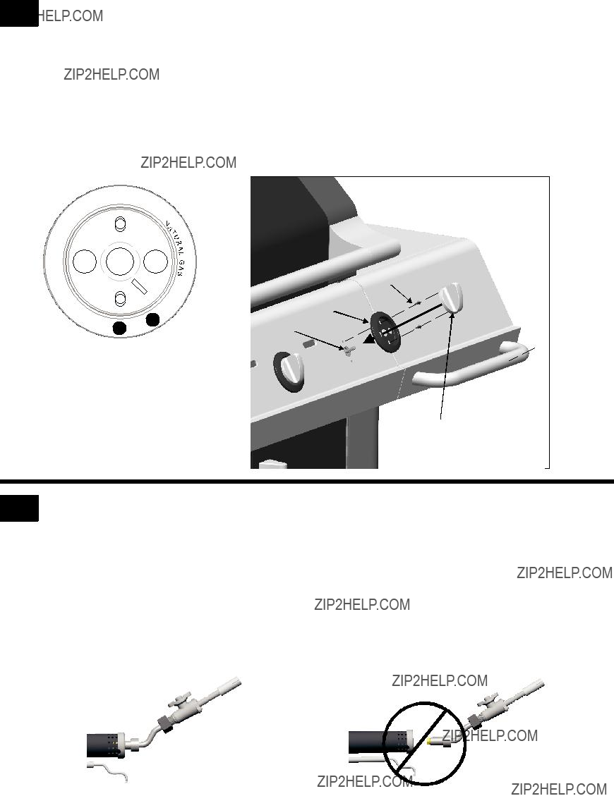
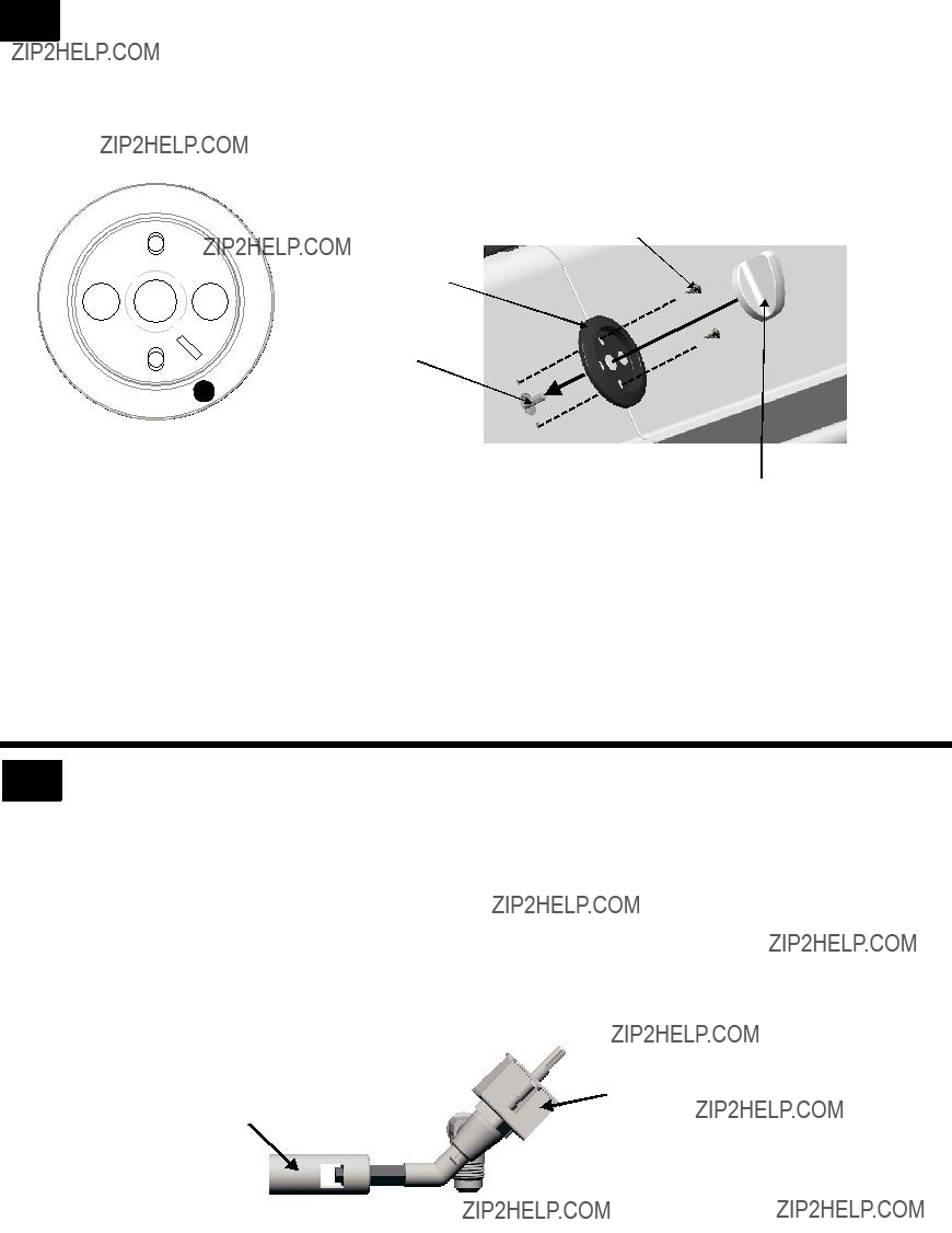
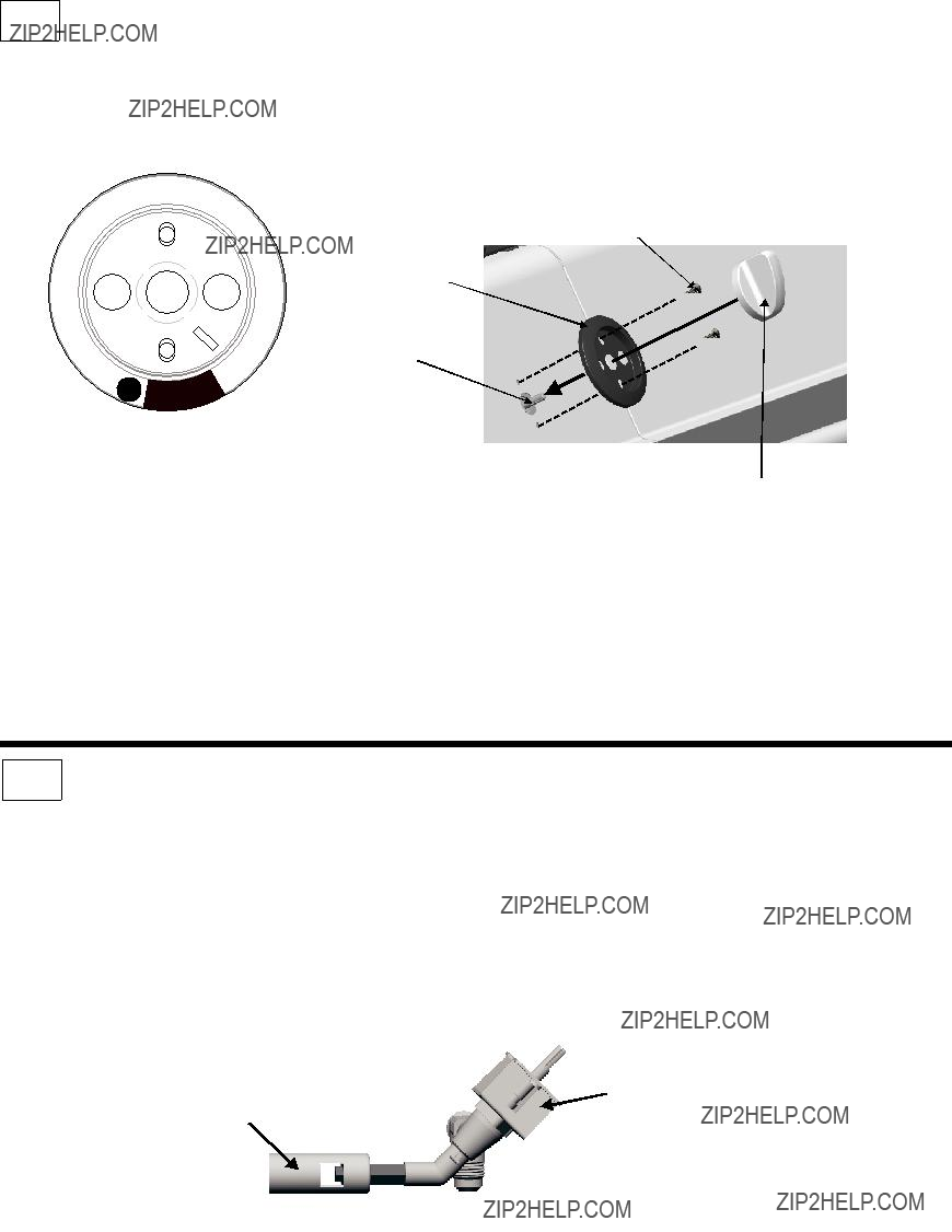
 5mm lock washer
 5mm flat washer
 Drawer right panel


 CAUTION