Introduction
Thank you for purchasing the Canon Network Camera Server VB101 (referred to hereafter as the VB101).
This manual describes how to set up and use the VB101. Read this manual carefully before using the VB101 to ensure effective operation. In particular make sure that you read the "aSafe Use of Equipment" in this manual, as well as the supplied CD-ROM Readme file.
Exclusion of Liability
If the Product is connected to a recording device (for example a VCR), Canon Inc. accepts no responsibility whatsoever for any financial losses that may be incurred as a result of the loss of recorded information or images, regardless of the internal or external cause of the loss.
Copyright Information
Video or still pictures recorded using your VB101 cannot be used in ways that infringe copyright laws or without the consent of the owner, unless intended for personal use only.
Notes
1.The unauthorized transfer of all or any part of the contents of this Manual is forbidden.
2.The contents of this Manual are subject to change without notice.
3.Every effort has been made to ensure that this Manual is flawless. However, if you find any oversights, please let us know.
4.Item 3. notwithstanding, Canon accepts no responsibility for any effects resulting from the use of this Manual.
Trademark Notices
???Canon and Canon logo are registered trademarks of Canon Inc.
???Microsoft and Windows are registered trademarks of Microsoft Corporation in the United States and other countries.
???Windows is legally recognized as Microsoft Windows Operating System.
???Other brand or product names in this manual may be trademarks or registered trademarks of their respective companies.
Request concerning disclosure of live videos
With respect to the disclosure of live videos, we request that sufficient consideration be given to matters of privacy and rights not to be photographed. Canon considers the following points concerning such matters when it operates camera sites for which it has been responsible to install and operate:
-We take measures such as adding limitations on zoom magnifications so that people cannot make special specifications.
-When videos are taken of specific buildings, interiors and the like, we install the camera only after
receiving approval from the administrator.
Please note that the operator of the camera site and not Canon has full responsibility regarding the disclosure of live videos.
?? Copyright 2002 CANON INC.
ALL RIGHTS RESERVED

FCC NOTICE
Network Camera Server VB101 (D78-0138)
This device complies with Part 15 of the FCC Rules. Operation is subject to the following two conditions: (1) This device may not cause harmful interference, and (2) this device must accept any interference received, including interference that may cause undesired operation.
Note: This equipment has been tested and found to comply with the limits for a Class B digital device, pursuant to Part 15 of the FCC Rules. These limits are designed to provide reasonable protection against harmful interference in a residential installation. This equipment generates, uses and can radiate radio frequency energy and, if not installed and used in accordance with the instructions, may cause harmful interference to radio communications.
However, there is no guarantee that interference will not occur in a particular installation. If this equipment does cause harmful interference to radio or television reception, which can be determined by turning the equipment off and on, the user is encouraged to try to correct the interference by one or more of the following measures:
-Reorient or relocate the receiving antenna.
-Increase the separation between the equipment and receiver.
-Connect the equipment into an outlet on a circuit different from that to which the receiver is connected.
-Consult the dealer or an experienced radio/TV technician for help.
Use of shielded cable is required to comply with class B limits in Subpart B of Part 15 of FCC Rules.
Do not make any changes or modifications to the equipment unless otherwise specified in the manual. If such changes or modifications should be made, you could be required to stop operation of the equipment.
Canon U.S.A. Inc.
One Canon Plaza, Lake Success, NY 11042, U.S.A. Tel No. (516) 328-5600
IC NOTICE
This product does not exceed the Class B limits for radio noise emissions from digital apparatus as set out in the Interference-causing equipment standard entitled ???Digital Apparatus???, ICES-003 of the Industry Canada.
NOTIFICATION IC
Cet appareil num??riquw respecte les limites de bruits radio??lectriques applicables aux appareils num??riques de Classe B prescrites dans la norma sur le mat??riel brouilleur: ???Appareils Num??riques???, NMB-003 ??dict??es par I???lndustrie Canada.
Dieses Produkt ist zum Gebrauch im Wohnbereich, Gesch??fts- und Gewerbebereich sowie in Kleinbetrieben vorgesehen.
a Safe Use of Equipment
3 a IMPORTANT SAFETY INSTRUCTIONS
In these safety instructions, the word ???equipment??? refers to the Canon Network
Camera Server VB101 and all its accessories.
1.Read Instructions - All the safety and operating instructions should be read before the equipment is operated.
2.Retain Instructions - The safety and operating instruction should be retained for future reference.
3.Heed Warnings - All warnings on the equipment and in the operating instructions should be adhered to.
4.Follow Instructions - All operating and maintenance instructions should be followed.
5.Cleaning - Unplug this equipment from the wall outlet before cleaning.
Wipe the equipment with a clean soft cloth. If necessary, put a cloth in diluted neutral detergent and wring it well before wiping the equipment with it. Finally, clean the equipment with a clean dry cloth. Do not use benzene, thinner or other volatile liquids or pesticides as they may damage the product???s finish.
When using chemically-treated cleaning cloths, observe those precautions accordingly.
6.Accessories - Do not use accessories not recommended in this manual as they may be hazardous. Always use specified connection cables. Connect devices correctly.
7.Water and Moisture - Hazard of electric shock - Do not use the equipment near water or in rainy/moist situations. Do not put a heater near this equipment.
8.Placing or Moving - Do not place on an unstable cart, stand, tripod, bracket or table. The equipment may fall, causing serious injury to a child or adult, and serious damage to the equipment. An equipment and cart
combination should be moved with care.
Quick stops, excessive force, and uneven surfaces may cause the equipment and cart combination to overturn.
9.Power Sources - The PA-V16 AC adapter should be operated only from the type of power source indicated on the marking label. If you are not sure of the type of power supply to your home, consult your equipment dealer or local power company.
10.Polarization - The PA-V16 AC adapter is equipped with a polarized 2-prong plug (a plug having one blade wider than the other).
The 2-prong polarized plug will fit into the power outlet only one way. This is a safety feature. If you are unable to insert the plug fully into the outlet, try reversing the plug. If the plug still fails to fit, contact your electrician to replace your obsolete outlet. Do not defeat the safety purpose of the polarized plug.
11.Power Cord Protection - Power cords should be routed so that they are not likely to be walked on or pinched by items placed upon or against them. Pay particular attention to plugs and the point from which the cords exit the equipment.
12.Outdoor Antenna Grounding - If an outside antenna is connected to the equipment, be sure the antenna is grounded so as to provide some protection against voltage surges and built-up static charges. Section 810 of the National Electrical Code, ANSI/
NFPA No.70-1984, provides information with respect to proper grounding of the mast and supporting structure, grounding of the lead-in wire to an antenna discharge unit, size of grounding conductors, location of antenna antenna discharge unit, connection to grounding electrodes, and requirements for the grounding electrode. See figure 1.
4 Maintenance
Cleaning the Equipment
1. Unplug the AC adapter from the wall outlet.
2. Carefully wipe the equipment with a soft cloth that has been moistened with water or a mild detergent.
 WARNING
Do not use flammable solvents such as alcohol, benzene or thinners.
The use of such substances can cause a fire or electric shock.
3.Wipe with a dry cloth.
4.When you have finished, plug the AC adapter back in to the wall outlet.
Icons Used in This Instruction Manual
c Indicates important information that must be observed or actions that are prohibited during an operation. These notes must be read to
Note prevent possible faults or damage to the equipment.
e Indicates supplementary information or a reference to an operation. Users are advised to read these memos.
Tip
 Chapter 1
Before Using the VB101
This chapter contains information that you should read before using the VB101. It also describes the features of the VB101, the system configuration, the hardware and software requirements, and the name and functions of the system components.

The VB101 is a system that distributes live videos via the Internet or an Intranet. It can be used in a wide
variety of applications such as distributing live videos or monitoring from a Web site. The system is
configured of the VB101 and viewer software. Please use the supplied viewer software to view videos
distributed from the VB101 or to control a camera.
???Broad band Video Distribution Function
Video can be captured at a maximum of 30 fps. Motion-JPEG is used to compress the video
images. The network auto switches between Ethernet 100 MBPS and 10 Mbps, and if a PC card
modem is used, the analog public line network or the PFS network (PIAFS) can also be used.
Since video quality (1-99) and the frame rate (0.1-30 fps) can be freely set, video can be
distributed under conditions that best suit the network bandwidth.
???Simultaneous video reception by up to 40 users
Up to 40 clients can view videos simultaneously with a single VB101 unit.
???Remote camera control from the viewer
Two types of viewer software are provided: Helper Viewer and Java Viewer. These viewers can be used to freely control the angle (pan and tilt) and the zoom magnification of cameras installed in a remote location, enabling viewing videos with plenty of ambiance.
???Control for up to 4 cameras
Up to 4 video cameras can be connected to the VB101, and videos that you view can be switched from the viewer. If Canon Communications VC-C4/VC-C4R cameras are used, you will be able to control all cameras (using the cascade function of the VC-C4/VC-C4R).
???Panorama picture creation function and various settings
The camera's entire recordable area can be created as a panorama picture and saved. The saved picture can then be used to easily and visually set view restrictions and presets.
???Camera position preset function
When presets such as camera angles (direction in which camera is aimed or zoom position) are stored in advance, the camera can be controlled by simply selecting the desired preset from the viewer. Up to 8 sets of presets can be stored.
???View restriction function
Restrictions can be applied to zoom magnifications and angle settings to prevent viewers from seeing certain camera angles. When using the VB101 to operate a fixed point camera over the Internet, for example, it is possible to consider privacy when distributing videos (page 1, "Request Concerning the Disclosure of Live Pictures").
???Built-in Web server and FTP server
The VB101 has a built-in Web server. If Web page data is written onto a flash memory card (sold separately), the VB101 will be able to distribute Web pages and videos over the Web. Since the VB101 also has a built-in FTP server, Web page data can be sent from a remote location as a file (FTP).
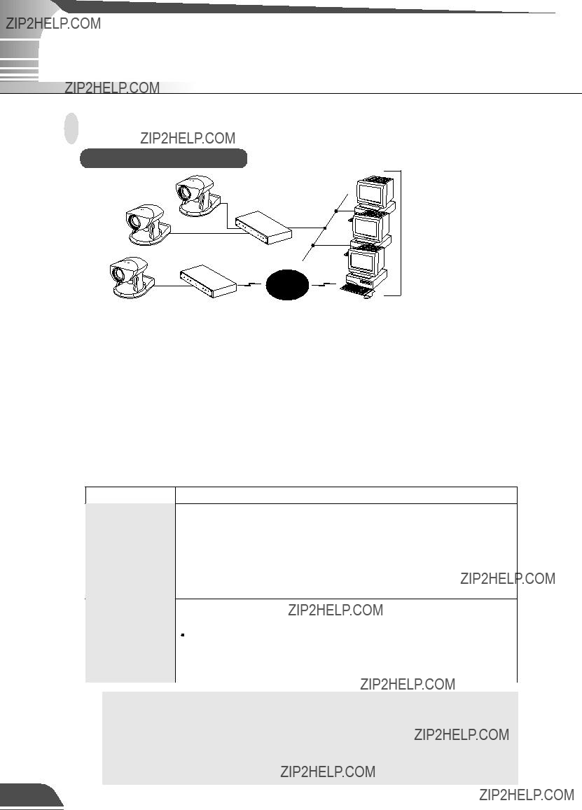
Example of basic system configuration - Viewing videos using a viewer
Sample system configuration
Internet
This system configuration consists of the VB101 with WebView Livescope Viewer Software (??? P.18). The WebView Livescope Viewer Software consists of the Helper Viewer and the Java Viewer.
Helper Viewer must be installed in advance from the supplied CD-ROM, while Java Viewer is not installed in advance but automatically downloaded from the VB101. Since Java Viewer is downloaded each time you want to view videos, it is useful when viewing videos for the first time. Helper Viewer, however, is more convenient when you want to view videos frequently.
If you want to distribute live videos of places such as popular tourist destinations from Web pages, it is best for your Web page visitors to use the Java Viewer that does not need to be installed in advance.
???Viewer software types and functions
 Videos from the VB101 can be displayed by a Web browser that can run Java applet.
 Because the Java Viewer is automatically downloaded and does not need to be pre-installed, unlike the Helper Viewer, it is compatible with any platform that supports Java-capable environments.
Java Viewer  Because it uses the HTTP protocol, the Java Viewer penetrates firewalls. However, it may not run stably on some platforms or browser types.
Also, because the Viewer is downloaded when the Web page loads, start-up times and execution speeds are slower than the Helper Viewer.
 A helper application for viewing videos from the VB101 that is launched from a Web browser.
 The Helper Viewer must be pre-installed.
Install Helper Viewer from the supplied CD-ROM.
 Compared with the Java Viewer, start-up is faster because the Viewer does not need to be downloaded. This Viewer is recommended for users who use it frequently.
 Because it supports the HTTP protocol, the Helper Viewer penetrates firewalls unscathed.
???To connect the VB101 to the Internet, you require a leased line connection to an Internet service provider or a LAN-type dialup IP connection. If you are using a LAN- type dialup connection, check that the connection supports bidirectional calling.
???Install Helper Viewer from "Mo Setup.exe" on the supplied CD-ROM.
???The WebView Livescope user's manual is on the supplied CD-ROM. (Mon-E.pdf)
Hardware and Software Requirements
Webview Livescope Viewer Software (??? P.16)
The viewer software that are supplied with the VB101. They lets you view the
VB101???s videos and control the camera.
Java Viewer version 3.20
*This viewer is installed on the VB101 and is automatically downloaded by the client at access.
*This software may not run stably on operating systems and Web browsers other than those listed above.
Helper Viewer version 3.20
* Must be installed from the supplied CD-ROM. (??? P.16)
???Although the Helper Viewer ver.3.10 or before, or the Plugin Viewer can be used, some of the features are different.
On Macintosh computers, some of the functions of the Helper Viewer ver. 1.20 are not available.
???The manual for the viewer software is on the supplied CD-ROM(Mon-E.pdf).
VB Administration Tools (??? P.62)
This tool lets you create panorama pictures from the VB101 and then easily use them to visually
set view restrictions and presets.
* Must be installed from the supplied CD-ROM. (??? P.64)
VBCollector (??? P.127)
This tool is for viewing still pictures recorded by the VB101.
* Must be installed from the supplied CD-ROM. (??? P.128)
Hardware and Software Requirements
Webview Livescope MV version 2.0/LE (??? P.17)
This is optional viewer software for monitoring.
Compatible Cameras (Sold separately)
Compatible Networks
???10 Base-T/100 Base-TX Ethernet (auto-negotiation)
???Public switched telephone networks (Use a recommended modem card)
Compatible PC Cards (Sold separately)
Use a recommended PC card. For further information, contact your Canon dealer. URL: http://www.canon.com/webview/
Compatible Cables (Sold separately)
RS-232C cables for camera control, and video cables are available as optional accessories in lengths other than the ones provided. For further information, contact your Canon dealer.
The VB101 package contains the following items. If any of these items is missing, please contact
the retailer from which you purchased the product.
1. VB101 main unit
3. AC cable (1 meter 3 ft. 3/32 in.)
*The cable length may differ depending on the country in which the product was purchased.
5.RS-232C cable
(miniDIN-Dsub9pin Female sub)
??? For setup, 3 m (9 ft. 10 3/32 in.)
7.User's Manual (This document)
8.Warranty Card
2. AC Adapter PA-V16
4.RS-232C cable (miniDIN-miniDIN)
???For camera control, 3 m (9 ft. 10 3/32 in.)
6. CD-ROM
CD-ROM contents
Readme (Notes of caution, etc., not in the main manual)
VB101_IP.exe (IP address setting tool)
MonSetup.exe (Helper Viewer ver. 3.20 installer) AdmSetup.exe (VB Administration Tools installer) CltSetup.exe (VBCollector installer)
IniVB101.exe (Tool for factory default settings) inivb101.elf (Tool data for factory default settings) vbrfu.exe (Remote firmware upgrade utility) VB101V3E.pdf (PDF file of this manual) Mon-E.pdf (Helper Viewer ver. 3.20 user's manual) Vbfiles (complete built-in file system)
System Components and Their Operation
Front View
 Power LED
 Slot-A LED
(Shows the operation status for card slot A)
 Slot-B LED
(Shows the operation status for card slot B)
100 LED
(Shows the Ethernet 100/10 operation mode)
Tx/Lnk LED
(Shows the Ethernet transmission status)
Col/Rx LED
(Shows the Ethernet reciving status)
c If the Power LED illuminates in orange before the VB101's initial settings have
been made, this does not indicate a malfunction.
System Components and Their Operation
Rear View
 Power connection socket
 External device I/O terminals
 Card slot A
(supports modem card and flash memory card)
 Card slot B
(supports modem card and flash memory card)
 100/10 BT Ethernet connector
(100Base-TX, 10Base-T auto-negotiation)
Console connector terminal  for initial setup and servicing
(RS-232C)
Camera control connector CC1, CC2 
(RS-232C, with one touch lock)
Video input sockets V1, V2 
(RCA pin-jack)
Video input sockets V3, V4 
(BNC connector)
The video cable supplied with the Canon Communication Camera VC-C4/VC-C4R is compatible with the RCA pin-jack. To connect these cameras to a BNC socket, use a third party Pin ??? BNC conversion adapter.
 Chapter 2
Installation
This chapter explains how to connect the system components and
describes a sample network configuration.
Precautions for Switching the VB101 On and Off
The VB101 has no power switch. To switch the VB101 off and on, unplug the AC adapter. When you unplug the AC adapter from the VB101, wait at least 5 seconds and then plug the AC adapter to the VB101. Be sure to observe the precautions given in "aImportant Safety Instructions".
AC Outlet
???Refer also to the enclosed ReadMe file. The ReadMe file may contain important information not included in this manual. Be sure to read this file.
???If the VB101 will not be used for some time, unplug the AC adapter from the power supply.
Connecting the Components
VC-C4
Camera
VC-C4
Camera
Camera
Camera
Connecting the Components
Cascade connections for the VC-C4 and VC-C4R
The cascade function of the VC-C4/VC-C4R can be used with the VB101. This enables control of up to 4 cameras from a single VB101.
??? When VC-C4/VC-C4Rs are cascade connected, ID numbers in ascending order from 1 are assigned to each camera starting with the first camera connected to camera control connectors CC1 and CC2. Cameras can be connected to Video inputs in any desired combination.
CC1
V1
V2
??? In cascade connections, if an abnormality occurs with the first camera in the connection, control for all other cameras in the cascade may not work normally.
Sample Network Configurations
This section describes some typical installation modes for the VB101.
Be sure to assign a fixed IP address o the VB101.
Sample LAN Environment Configuration
Provide the appropriate server as required:
??? HTTP (WWW)
??? SMTP (mail)
??? Syslog (log)
??? BOOTP
Server
VB101
Viewer PC
RouterRouter
Viewer PC
This example shows the VB101 connected to a LAN by Ethernet. In this configuration, videos can be seen by viewers in the same Ethernet segment as the VB101 and by viewers with access to that segment.
To send log information such as faults and access statuses by e-mail and save that information to another computer, an SMTP server or a Syslog server is required.
To automatically assign an IP address for the VB101, a BOOTP server is required.
Sample Dialup Environment Configuration
Sample Network Configurations
LAN plus Dialup Environment
Sample Configuration in an ISP Environment
??? HTTP (WWW)
??? SMTP (mail)
??? Syslog (log)
Analog line
Viewer PC
Internet
ISDN/
leased line, Router ADSL/etc
leased line/ADSL, etc
This example shows an environment in which the VB101 is connected to an ISP (Internet service provider). In this configuration, videos can be seen by viewers capable of accessing the ISP. Bidirectional communication is required between the VB101 and the ISP, and a fixed IP address must be set for the VB101.
 Chapter 3
Setup Procedures
This chapter describes the procedures from the initial setup of the VB101 through to operation checking and the method for specifying detailed settings.
The VB Administrator Tools described in Chapter 4 provide a convenient way to set view restrictions and presets.
Once you confirm the operating environment, the VB101 can be used immediately after initial settings have been made. Make these settings starting with "Initial Setup" (??? P.33) followed by "Checking Operation" (??? P.35).
To make initial settings on the VB101, connect it to a PC using the cable supplied with the VB101, and start up the IP address setting tool provided on the supplied CD-ROM. Network connection settings are made via an easy Wizard-style process.
 P.35
P.35
After the initial settings have been made, the VB101 must be checked to be sure it operates normally. Use the Web browser to access the sample page that has been prepared in advance for the VB101.
c Install the Web browser on your PC beforehand.
Note
Initial Setup
When you connect a LAN cable, turn off the VB101 power. After connecting the LAN cable, turn the VB101's power on.
1Launch the browser and enter the following URL: http://192.168.100.1/admin/
2 Enter the user name and password. User name: root (default setting) Password: VB101 (default setting)
3 The Settings Title Page is displayed.
Settings Title Page
The user name and password can be changed on the System Setting page. (??? P.39)
c The IP address "192.168.100.1" is given as an example. However, the actual IP
Note address must be changed to match your system settings.
c ??? Before check the operation, install the Web browser on your PC.
Accessing the Settings Title Page
The various settings on the VB101 are specified by using a browser to access Web pages on the VB101. You begin by accessing the Settings Title Page.
Use the browser to access http://192.168.100.1/"path".
Use the IP address specified in "Initial Setup" (??? P.33) and in the "path" field, use the path specified in "System Settings page" (??? P.39). The default setting for "path" is "admin".
Enter the user name and password.
You are now asked for your user name and password. In the factory default settings, the user name is "root" and the password is "VB101". Enter these settings. These can be changed at any time from the "System Settings page". (??? P.39)
Indication of the settings title page
The configuration of the settings pages that can be accessed from the settings title page varies greatly depending on whether Webview Livescope or VIEW-Windows is selected as the target application in "Basic Settings".
VIEW-Windows is an optional product designed specifically for use within Japan. Do not select VIEW-Windows 1.21. (??? P.38)
Detail Settings
Settings Title Page
The various settings on the VB101 are specified by using a browser to access Web pages on the VB101. From this title page, you can move to each settings pages and confirm the changes to the settings, write the changes to the VB101 memory and perform restarts.
Settings Title Page for VB101
 Clicking on the titles displays each setting pages.
 "Japanese" button
Click this button to display the settings page in Japanese. The button then changes to "English" and switches the display back to English when clicked.
 "Send Config. and Reboot VB101." button
After you have changed the settings on a page, click the "OK" button on that page. This returns you to the title page. At that point, the changes have not been sent to the VB101. Clicking this button confirms the changes, writes them into the VB101 memory and automatically restarts the VB101 to validate the changes. If the changes do not require restarting, the "Send Config. to VB101" button is displayed instead of this button.
 "Restore to previous VB101 Config" button
Click this button when you want to cancel the changes you have made to the settings page. All the changes are discarded and returns to its previous values.
 If no settings have been changed, these 2 buttons are not displayed.
Click the [OK] button when you have changed the settings. To discard the changes, click the [Cancel] button. You are then returned to the settings title page.
Detail Settings
Basic Settings Settings Page
This page contains indispensable settings taken from the various settings pages for the VB101. If values are specified for these settings on other pages, the most recent change is valid.
 Ethernet
The same settings can be specified on the Network settings page.
"Use Ethernet"
Tick this checkbox to use Ethernet.
"Address Settting Method"
If you select "Auto Setting (Bootp)", the IP address is automatically acquired by the Bootp server after restart. If you select "Manual Setting", enter the IP address and subnet mask also.
"IP Address"
Enter a network interface-specific IP address.
"Subnet Mask"
Enter the subnet mask specified for the network to be connected.
"Default Gateway Address"
Specify this setting when you are connecting to a wide area network such as the Internet.
 If you selected "Auto Setting (Bootp)" as the address setting method, check that the Bootp server has been started up.
 Contact the network administrator for the IP address, subnet mask, and default gateway address settings.
Administration Account
The same settings can be specified on the System settings page.
"Administrator ID"
Sets the ID used by the administrator. Up to 15 characters can be set consisting of alphanumeric characters, underscores and hyphens. The default setting is "root".
"Password"
Sets the password. Up to 15 ASCII characters can be used (space or printable characters). The default setting is "VB101".
"Confirm Password"
Confirms the password in the field above.
Target Application
Chooses " Webview Livescope" or "VIEW- Windows 1.21" as the application used by the VB101.
VIEW-Windows is an optional product designed specifically for use within Japan. Do not select VIEW-Windows 1.21.
Click the [OK] button to change the settings. To discard the changes, click the
[Cancel] button. This returns you to the title page.
Detail Settings
System Settings Page
Use this page to set the administrator ID and password as well as the date and time.
 Others
"Device Name"
Sets the device name (nickname). The device name is used for log mail etc.
Administration Account
The same settings can be specified on the Basic Settings settings page.
"Administrator ID"
Sets the ID used by the administrator. Up to 15 characters can be set consisting of alphanumeric characters, underscores and hyphens. The default setting is "root".
"Password"
Sets the password. Up to 15 ASCII characters can be used (spaces or printable characters). The default setting is "VB101".
"Confirm Password"
Confirms the password in the field above.
Settings Web Page URL
Sets the "path" component for the settings title page. This URL is used subsequently when you access the settings title page after restarting the system. (Up to 31 characters can be set consisting of alphanumeric characters, underscores and hyphens.).
The default setting is "admin".
Date and Time
"Time difference with Greenwich Mean Time" The factory default time difference setting is set to +9 hours from Greenwich Mean Time. Please change this setting as needed.
You can only change the time on the VB101 when the "Set the clock to the following time" option is ticked. Because this setting is returned to the VB101 when the "Send Config. and Reboot VB101" button is clicked, the values for the settings from year to second must be matched to the time when the button is clicked.
Click the [OK] button to change the settings. To discard the changes, click the
[Cancel] button. This returns you to the settings title page.

Detail Settings
Network Settings Page
Use this page to specify the settings for connecting to an Ethernet or PPP network.
For a LAN connection, specify Ethernet settings. For connections made with a modem, specify PPP settings.
Ethernet
The same settings can be specified on the
Basic Settings settings page.
"Use Ethernet"
Tick this checkbox to use Ethernet.
"Address Setting Method"
If you select "Auto Setting (Bootp)", the IP address is automatically acquired by the Bootp server after restart. If you select "Manual Setting", enter the IP address and subnet mask also.
"Give priority to Bootp option when deciding subnet mask."
If you tick this option, the subnet mask specified by the Bootp server is given priority over the subnet mask address specified below when "Auto Setting (Bootp)" is selected as the address setting method.
"Give priority to Bootp option when deciding gateway address."
If you tick this option, the gateway address specified by the Bootp server is given priority over the default gateway address specified below when "Auto Setting (Bootp)" is selected as the address setting method.
"IP Address"
Enter a network interface-specific IP address.
"Subnet Mask"
Enter the subnet mask specified for the network to be connected.
 If you selected "Auto Setting (Bootp)" as the address setting method, check that the Bootp server has been started up.
 Contact the network administrator for the IP address, subnet mask, and default gateway address settings.

 The items below are valid when "Use PPP" and "Primarily Call (PPP)" are selected.
"Dial Method"
Select the type of line to be used when Primarily Call(PPP) is selected.
"Phone Number"
Set the phone number to be dialed when Primarily Call(PPP) is selected.
"User Name"
Enter the user name to be used when Primarily Call (PPP) is selected.
"Password"
Enter the password to be used when Primarily Call (PPP) is selected.
"Confirm Password"
Re-enter the password you entered above to confirm the password.
PPP
"Use PPP"
Tick this option to allow PPP connections using a modem cards.
"Receive and Call"
If Receive only (PPP) is selected, PPP connection will be established by incoming call, and if Primarily Call (PPP) is selected, PPP connection will be established by outgoing call.
"Country Selector"
When the global modem is used, select the country where the VB101 will be used.This setting is ignored if the global modem is not used.
"Modem max speed"
Select the maximum baud rate as the limit on the Modem speed. The available settings are 4800, 9600, 19200, 38400, 57600 and 115,200. Normally, there is no need to change this setting. Set a low speed when the line condition is poor.
"PPP Local Address"
Sets the local address. For PPP connections, this address is set for the VB101 side.
"PPP Remote Address"
Sets the remote address. For PPP connections, this address is set for the Viewer PC or router side.
"PPP Account List"
PPP connection is only permitted to accounts with combinations of a name and a password that match those included in this list. (Passwords are not displayed in the list.) If you select an account and click the "Delete" button, the combination of a account name and a password is removed from the list. Up to 10 accounts can be registered on the list.
"Add PPP Account"
Use this to add account and password combinations to the PPP account list. Enter the account name and password, and click the "Add" button. The account name can be up to 15 characters including alphanumeric characters, underscores and hyphens. Passwords can consist of up to 15 ASCII text characters (space or printable characters).
??? If you are using PPP, take care when entering the phone number. Also, when c Primarily Call(PPP) is selected, the VB101 will continue calling to the
Note specified phone number. Be mindful of phone charges that apply when using Primarily Call(PPP).
???If you have selected Primarily Call(PPP), appropriate settings must also be made on the receiving PC.

Detail Settings
Static Route Control
Route settings are required when communicating with a wide-area network through a router. When using both Ethernet and PPP, set the route as needed.
"Default route"
The same setting can be made at "Default gateway address" on the Basic Settings settings page. Specify the route that would normally be used. A gateway address is required if a router on the Ethernet side is used.
"Route 1-3"
Use this setting if you require connection routes other than the normal route. You can select either Ethernet or PPP as the interface. Specify the destination route in the Destination and Mask fields. You must specify a gateway address if you are using a router on an Ethernet network.
Connection Keeping
"Send packet regularly"
When this is selected, an ICMP Echo packet is transmitted periodically to a specified address in order to maintain the network connection.
"Target Address"
Specify where the PING should be sent.
"Interval(min)"
In minutes from 1 to 60, specify the interval at which PING should be sent.
For the packet target address in the connection keeping function, we c recommend that you consider the impact on traffic conditions and set the IP
Note address that is nearest after the auto dial-up router.
Router
Internet
ISDN/leased line/
ADSL, etc
VB101
Click the [OK] button to change the settings. To discard the changes, click the
[Cancel] button. This returns you to the settings title page.
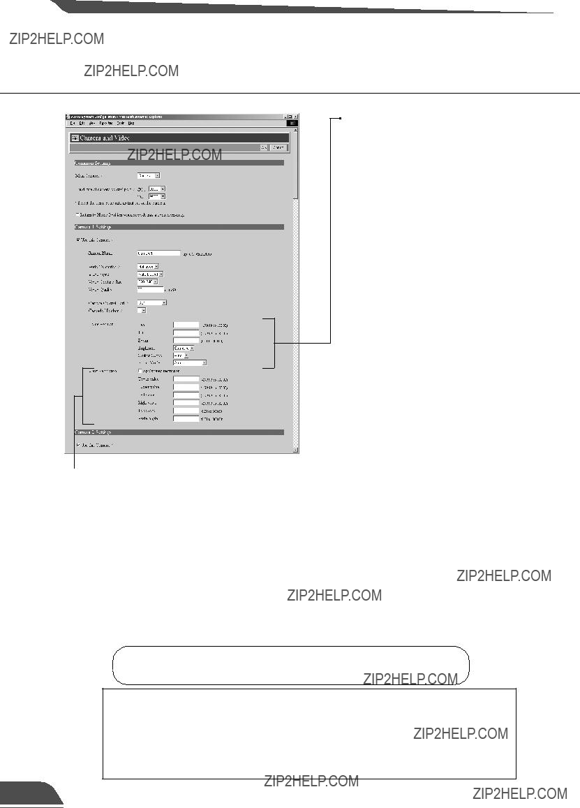
 "View Restriction"
If you tick the "Apply View restriction" option, the settings below are enabled. Use this setting to prevent clients from seeing certain camera angles. Using the VB Administration Tools is a convenient way to set the view restrictions (??? P.73).
"Upper value, Lower value, Left value, Right value" Sets the extent of the field of view provided to users.
(Specify settings so that the upper value is greater than the lower value and the left value is less than the right value.)
"Telephoto, Wide-angle"
Sets the zoom angles provided to users.
(Specify settings so that the telephoto setting is less than or equal to the wide-angle setting.)
"Camera Control Port"
Select the camera control connector (??? P. 22) to which the camera is connected. Select "Not controlled" for cameras that are not connected or not controlled.
"Cascade Number"
If cameras are cascade connected, select numbers assigned to the cameras. Numbers in ascerding order from 1 are assigned to each camera starting with the first camera connected to camera control connector CC1 and CC2.
"Home Position"
This is the standard camera position used for picture recording, etc.
"Pan"
Sets the pan position of the camera.
"Tilt"
Sets the tilt position of the camera.
"Zoom"
Sets the value for the camera's angle of zoom.
"Brightness"
Sets the target value for the camera's auto exposure feature. Select "Brighter " if the picture is darker due to backlight or other factor.
"Shutter speed "
Sets the camera shutter speed. Select Auto, 1/60 or 1/100.
"Focus Mode"
Sets the focusing mode for the camera. Select "Auto" (auto focus), "Auto (for domes)", or "Fixed at infinity" (focus fixed at infinity).
Click the [OK] button to change the settings. To discard the changes, click the [Cancel] button. This returns you to the settings title page.
???View restrictions can be set visually and more easily from the VB
Administration Tools. Please use the VB Administration Tools for the settings (??? P.73).
???When the VC-C4/VC-C4R are used in combination with an outdoor housing, set Focus Mode to "Auto (for domes)," in order to avoid focusing on the wall of the outdoor housing.
About View Restriction
??? The pan and tilt range changes with the zoom ratio (field of view angle).
Angle of camera movement
Camera
Captured range
If the visible range is exceeded because the zoom is set to wide range, the camera angle (pan, tilt) will be adjusted automatically.
Captured range
Restricted range of visibility
??? If the visible range is restricted, the zooming range may also be restricted.
Detail Settings
Preset Settings Page
Use this page to specify the settings for preset camera positions provided to viewers.
Using the VB Administration Tools is a convenient way to set presets (??? P.79).
Changes in the preset settings are not c applied to the viewer while it is
Note connected.
Preset Common Setting
"Restrict Camera Control to Presets" Camera control by using the Helper Viewer and the Java Viewer can be restricted to the preset angles specified in Preset 1-8.
Presets 1-8
Up to 8 presets can be specified.
"Application"
Use these options to specify whether this preset can be used only for picture recording (??? P.48) or is also made available in WebView Livescope Viewer. If it is also provided in WebView Livescope Viewer, always specify the preset name.
"Preset Name"
Enter a name consisting of up to 15 alphanumeric characters.
"Camera"
Selects the camera for which the preset position is set.
"Camera Parameter"
Use this to set the video capture settings to be provided.
"Pan"
Sets the pan position of the camera.
"Tilt"
Sets the tilt position of the camera.
"Zoom"
Sets the value for the camera's angle of zoom.
"Brightness"
Sets the target value for the camera's auto exposure feature. Select "Brighter " if the picture is darker due to backlight or other factor.
Click the [OK] button to change the settings. To discard the changes, click the
[Cancel] button. This returns you to the settings title page.
??? If "Restrict Camera Control to Presets" is selected, the presets can be displayed alone without displaying the camera control GUI on the Java Viewer (??? P.102).
Detail Settings
Picture Recording and External Device I/O Settings Page
Use this page to specify the operating condition for the picture recording function. Settings on this page can be used to record still pictures in response to inputs from an external device (sensor, etc.) and based on a predetermined schedule (up to 10000 picures).
 "Recording Priority"
When there is a conflict between the timing of recording specified in a schedule and "Recording between ON event and OFF event", this setting specifies which recording takes priority. Tick "Recording triggered by external device" or "Recording triggered by schedule". The factory default setting gives priority to "Recording triggered by external device" .
Picture Recording Common Settings
"Max No. of Pictures to be Recorded" Specifies the upper limit for the number of pictures to be recorded. This value can be from 1 to 10,000.
"Auto Deletion of Recorded Pictures" Recorded pictures can automatically be deleted on the specified time after the specified number of days has passed.
"No. of days recorded pictures held" Specifies how many days the recorded picture data will be kept in a flash memory card. The recorded data which exceeded the days specified in "No. of days recorded pictures held" is erased daily at the time specified in "Recoreded picture delete time". In this manner, picture recording function does not keep data on a permanent basis, so use FTP to transfer the data files or replace the flash memory card when needed.
 Picture files are placed in the /card /images directory.
A Flash Memory card is required for recording pictures.
Files created at yyyy/mm/dd/HH/MM/SS/CC (CC = 1/100th sec. units) are placed in the yyyymmdd/HHQQ (QQ = 15-min. units) subdirectory under the name "HHMMSSCC.jpg".
"Recorded picture delete time"
Sets the time at which picture files are deleted.
???Still pictures are recorded on a flash memory card (sold separately). Even if the settings on this page are specified, the Picture Recording function does not perform if there is no memory card in the VB101 slot.
???The data size that can be recorded for a still picture is less than 32 KB. If this amount is exceeded, the picture will not be recorded. The number of pictures that can be recorded depends on flash memory card capacity, however the maximum number of pictures that can be recorded is 10000.
???The data size for a still picture varies depending on the settings for video capture size and video quality (??? P.43), and the subject. As a guide, approximately 5-10
KB is the standard when the video capture size is set to 320x240 and the video quality is set to 30 (In some cases this may be exceeded). To check the amount of data for a still picture, select "View" - "Video information" from the menu after you start up the Helper Viewer, then check the "Size" value.
???When recording pictures, it is convenient to do so in combination with VBCollector, which automatically collects recorded still pictures. (??? P.127)

Picture Recording and Output: by Schedule
Use this setting to operate the picture recording function based on a schedule set beforehand. For a detailed example of actual operation, see Chapter 6, "Using the Picture Recording Function". (??? P.120)
"Schedule 1 to 4"
"Record pictures"
When this option is ticked, picture recording is performed based on the settings below.
"Camera Position"
Selects the camera angle used for picture recording. Select "Not Specified", "Home 1" to "Home 4" or "Preset 1" to "Preset 8".
"Camera Stabilization Time (sec.)"
When the camera moves to the specified position, this setting specifies the delay time for the camera to stabilize before still picture is captured.
"Output to External Device 1/2"
Select this check box if output to external device 1/2 is to occur at the time given below.
"Output Time (sec.)"
Sets the duration for which output is ON at the specified time. If zero is specified, output is only ON momentarily.
"Start Time"
Sets the start time for picture recording and output to an external device triggered by the schedule.
"Apply the following repetition options at start time"
Picture recording and output to the external device after the Start Time is repeated at the number of times specified in "Repetition interval(min)" and "No. of repetitions".
Specify "No. of repetitions" between 1 and 60 at the interval.
Specify "Repetition interval(min)" between 1 and 10 minutes.
Click the [OK] button to change the settings. To discard the changes, click the
[Cancel] button. This returns you to the settings title page.
51
Detail Settings
Access Control Settings Page
From this page, you can permit access to the VB101 to specific authorized users only, and you can control who may and may not access from a specific host. In either case, access by restricted user is prohibited.
 Authorized/Restricted Host Specification (??? P.53)
"Authorized/Restricted Host List"
In this list, you can describe the details of how access to the hosts is permitted or denied.
See the next page for the description format.
"Apply this list to WebView Livescope"
When this is selected, the list is applied to the host that can access the WebView Livescope Server. Use this when you want to restrict access from the Helper or the Java viewers, etc.
"Apply this list to HTTP server"
When this is selected, the list is applied to the host that can access the HTTP server. In this case, control extends also to the Java Viewer, etc.Use this when you want to restrict access not only from the Viewer but also to the Web page.
"Apply this list to FTP server"
When this is selected, the list is applied to the host that can access the FTP server.
Authorized User Account (??? P.53)
"Authorized User List"
Only accounts registered in this list are permitted to connect to the VB101. Up to
30 users can be registered.
"Delete"
Select a user account and click the delete button to remove the user from the list.
"Add"
You can add authorized users to the list by entering their account name and password.
"Authorize access by listed users only" When this option is ticked, only users registered in the list are permitted to connect to the VB101.
 Access using the WebView Livescope Helper Viewer Ver.3.10 or before and WebView Livescope MV Ver.1.0 is prohibited.
Click the [OK] button to change the settings. To discard the changes, click the
[Cancel] button. This returns you to the settings title page.
Detail Settings
Listing Guidelines
Descriptions in the Authorized/Restricted Host List are extremely complex, and errors in the settings can result in access being prohibited where it should be permitted. To avoid this, follow the guidelines given below with great care.
1.Left-align the mask
172.20.0.0/255.255.0.0 -- Correct
172.0.28.0/255.0.255.0 -- Incorrect
2.Use denied entries mainly rather than permitted entries.
!172.20.26.0/255.255.255.0
!172.20.28.0/255.255.255.0
3.Make permitted entries subsets of denied entries.
172.20.26.0/255.255.255.0
172.20.28.0/255.255.255.0
!172.20.0.0/255.255.0.0
4.List specific entries before generic entries.
Not like this:
!172.20.0.0/255.255.0.0
172.20.28.0/255.255.255.0
Like this:
172.20.28.0/255.255.255.0
!172.20.0.0/255.255.0.0
5.Avoid risky settings.
0.0.0.0/255.255.255.255
10.0.0.0/0.0.0.0
Such specification are not prohibited, but will effectively prohibit access from all hosts. Avoid entry !0.0.0.0/0.0.0.0 in particular wherever possible.
???The default value for "mask" is 255.255.255.255.
???If you do not make a list, access is permitted to all hosts.
???If the list provided prohibits access for all hosts, the Host Restriction function is disabled and access is permitted to all hosts.
???To prohibit access over HTTP connection via a proxy server, the address of the proxy server must be set.
???If you set the host restriction incorrectly, access to the settings page itself may be denied. In this event, the problem can only be recovered by restoring the factory default settings. (??? P.160)
Detail Settings
Application Settings Page
Use this page to specify settings for each application. Only the application selected as the "Target Application" (??? P.38) in the Basic Settings settings page is shown on this page.
???When WebView Livescope is selected
"Restrict Service Time"
When you want to set service time for WebView Livescope Viewers, tick this option and specify the Start and End times.
The Admin Viewer can be used to display pictures at times other than the time specified. (??? P.88)
WebView Livescope
"Video Transmission Port"
Sets the TCP port number for the WebView Livescope video transmission protocol. Enter an integer between 1 and 65535. The default setting is 65310.
"Camera Control Port"
Sets the TCP port number for the WebView Livescope camera control protocol. Enter an integer between 1 and 65535. The default setting is 65311.
"Maximum Number of Clients"
Sets the maximum number of clients that can be connected simultaneously from the WebView Livescope Viewer. Enter an integer from 1 to 40.
"Control Queue Length"
Sets the length of the queue when multiple clients are waiting for control privilege under the WebView Livescope Viewer.
Enter an integer between 0 and 40. The maximum number is 40. When set to "0", only the Admin Viewer is permitted to control the camera.
"Maximum Frame Rate (fps)"
Sets the maximum number of frames captured per second. Enter a number between 0.1 and 30. The maximum frame rate is 30 fps.
"Maximum View Time (sec)"
Sets the maximum time the client can view videos using the WebView Livescope Viewer. Enter an integer between 1 and 65535. A setting of 0 disables the time limitation.
"Maximum Camera Control Time (sec)" Sets the maximum time for which camera control privilege can be maintained under the WebView Livescope Viewer. Enter an integer between 1 and 3600.
"Still Video Capture Delay Wait Time (msec.)"
When the GetStillImage command (??? P.114) has been requested, this setting specifies the delay to allow the camera to stabilize before still picture is captured. Enter an integer between 0 and 10000. The maximum delay is 10000 milliseconds.
VIEW-Windows is for sale in Japan only, it cannot be used in any other countries.
???When VIEW-Windows 1.21 is selected
VIEW-Windows 1.21
"Video Transmission Port"
Sets the TCP port number for the VIEW- Windows 1.21 video transmission protocol. The default setting is 5111.
"Camera Control Port"
Sets the TCP port number for the VIEW- Windows 1.21 camera control protocol. The default setting is 5110.
"Switcher Control Port"
Sets the TCP port number for the VIEW- Windows 1.21 switcher control protocol. The default setting is 5120.
"Maximum Number of Clients"
Sets the maximum number of clients that can be connected using the VIEW- Windows 1.21 protocol. Enter an integer between 1 and 10.
"Maximum Frame Rate (fps)"
Sets the maximum number of frames captured per second under the VIEW- Windows 1.21 protocol. Enter a real number between 0.1 and 30.
Click the [OK] button to change the settings. To discard the changes, click the
[Cancel] button. This returns you to the settings title page.
Detail Settings
Log
"Recipient Mail Address" Specifies the log mail recipient.
"Syslog Server Host" Sets the Syslog server.
"Maximum Log File Number"
Sets the maximum number of log files saved as back-up files. Enter an integer between 0 and 10. The maximum number is 10.
"Maximum Log File Size (K bytes)"
Sets the maximum log file size. Enter an integer between 16 and 1024. The maximum size is 1024 KB.
"Log mail collection time (min.)"
Log messages containing errors, warnings and other information are collected for a set period beginning from the first log entry. This setting specifies that collection period. Enter an integer between 0 and 60. The maximum time is 60 minutes.
"Handling of Error/Warning/Information" Tick the "File" option to save log messages to files.
Tick the "Forward" option to send the log messages to a Syslog server host. Tick the "Mail" option to send the log messages by email.
???The log message will be stored on the flash memory card (sold separately). Even if settings are made for this page, this function will not operate unless a flash memory card is inserted into the slot on the VB101.
???See Chapter 7 (???P.146 ) for log message details.
???The log message for external device input (sensor, etc.) is A023(??? P.148). If the "Log mail collection time" has been set, this message will be sent after a specified waiting time.
Click the [OK] button to change the settings. To discard the changes, click the
[Cancel] button. This returns you to the settings title page.
???Log files will be created in the /card/logs directory (a flash memory card is required to save log messages in a file). The most recent log file will be saved as "log". The log file size is specified in "Maximum Log File Size" and if the log file exceeds the specified size, back-up files named "log.0..." are created.
???Only the number of back-up log files that are specified in "Maximum Log File Number (N+1)" will remain. These will be listed in the order, "log.0, log.1,..., log.N". For example, if "Maximum Log File Number" is set to 10, files named "log.0, log.1,..., log.9" will be created in the same directory. The file named "log.0" is the most recent back-up file (the most recent log file is listed as "log").
???Log files will be overwritten in order after the number of files specified in "Maximum Log File Number" have been created.

Administration Tools Settings Page
 Miscellaneous
"View Current Settings"
Displays a list of current settings.
"Reboot"
Reboots the VB101.
"Restore Settings"
All but the Basic Settings, System settings and Network settings will be restored to the factory default settings. Click "Restore"-"OK" button and the VB101 will be rebooted automatically.
On-board File System Information
The On-board File System displays the used space, free space and capacity (used space + free space) in bytes.
Slot A/B
If a PC card, used for communications and storage, is inserted into the slot, the "Manufacturer" and "Product Information" is displayed. Depending on the card type and its status, the operation buttons are displayed and the card status can be controlled. The card slots are labelled A and B from the bottom upwards.
Recorded Picture Information and
Manipulation
This section displays the number of recorded pictures and the status of recorded picture processing. The maximum number of pictures that can be recorded is 10000. Under certain circumstances, the "Rebuild" button for "Rebuilding of recorded picture list" and the "Delete" button for "Deletion of recorded pictures" may be displayed, and if the pictures cannot be recorded the reason will be displayed.
"Rebuilding of recorded picture list" Normally, there is no need to reconstruct the picture list. Click "Rebuild" button if you have removed a memory card and modified the content of that memory card (erased files, etc.) on another PC.
"Deletion of recorded pictures"
Deletes pictures recorded on a card. Specify the Delete criteria below and then click the "Delete" button.
"Time"
Select the period of time following the recording of the pictures after which the pictures are deleted.
"Event"
Select whether the pictures to be deleted are those where recording was performed in response to inputs from an external device or according to a schedule. You can also select a combination of the two.
"Camera"
Select camera by which the pictures were recorded.
Click the [Cancel] button to exit from this page. This returns you to the
settings title page.
 Chapter 4
VB Administration Tools
This chapter describes how to use the VB Administrator Tools in order to create panoramas, set view restrictions, make presets, view logs, and use the Admin Viewer. Although view restriction and preset settings can be made following the procedures described in Chapter 3, the VB Administration Tools and their more visual environment make the settings much easier.
Overview of VB Administration Tools
VB Administration Tools is an application that simplifies the management and operation of the VB101.
VB Administration Tools comprises "VBAdmin Startup Panel" and "Panorama Creation Tool," "View Restriction Tool," "Preset Setting Tool," "Log Viewer," and "Admin Viewer" applications. Operations such as setting the VB101 or viewing pictures from a remote location with special privilege, checking operating status or obtaining logs are easily performed through the Internet or Intranet.
VC-C4
Remote operation, setting, and information gathering are possible through the Internet/Intranet .
Setting view restrictions
Setting presets
Viewing logs
Privileged viewing and operation
VBAdmin Startup Panel (??? P.66)
This is the main panel of VB Administration Tools.
The tools are started up from this panel.
Install VB Administration Tools first from the supplied CD-ROM.
Panorama Creation Tool (??? P.68)
This tool is used to take or create panorama pictures.
Overview of VB Administration Tools
View Restriction Tool (??? P.73)
This tool enables easier, more visual setting of view restrictions. Restrictions can be set by operating the mouse while referring to panorama previews.
Preset Setting Tool (??? P.79)
This tool enables easier, more visual setting of preset camera positions. Presets can be set by operating the mouse while referring to panorama previews.
Log Viewer (??? P.85)
This tool enables viewing of operation status logs that are output to the VB101.
Admin Viewer (??? P.88)
This tool has a special privileges function aimed at administrators of the VB101. Use it when setting presets, view restrictions, etc.
4
Tools Administration VB
Installing VB Administration Tools
VB Administration Tools require that Microsoft Internet Explorer 5.0 or later c be installed. Before installing VB Administration Tools, check to be sure that
Note
the correct version of Internet Explorer has been installed.
To Install...
1
If any other applications are running, please exit them before installation.
Load the supplied CD-ROM into the CD-ROM drive. Double-click ???AdmSetup.exe??? on the CD-ROM to start up the installer. Click the Next button.
Specify the target directory for the installation and click the Next button.
If you have no special directory preference, just click Next.
Specify the menu name to be registered in the Program menu of the Start button, then click Next.
Check the settings and items you have selected thus far, and click Next to confirm. The installation will proceed by copying files and making registry settings, etc.
Starting Up VB Administration Tools
VB Administration Tools can be started up using the icon created on the desktop or by selecting it from the Start menu.
When starting up tools from the VBAdmin Startup Panel, double click the VB Admin Tools desktop icon or select VB Admin Tools from the Start menu.
When VB Administration Tools starts up, the Server Setting dialog box appears. To use VB Administration Tools, it must first be connected to the VB101. Enter the required information in the fields and click OK.
???Host Name (??? P.38)
Specify the IP address or host name of the VB101.
???Administrator Account (??? P.38)
Enter the administrator account that has been set in the VB101. (The default setting is "root".)
???Administrator Password (??? P.38)
Enter the administrator password that has been set in the VB101. (The default setting is "VB101".)
???HTTP Port (??? P.57)
Enter the HTTP port number that has been set in the VB101. (The default setting is 80.)
???URL for settings (??? P.39)
Enter the "path" component for the settings title page that has been set in the VB101. (The default setting is "admin".)
???Proxy
*Please consult with the network admninistrator for proxy settings.
[Use HTTP Proxy Server]
Select this item if the connection to the VB101 is to pass through a proxy server.
[Host Name]
Specify the host name or IP address of the proxy server.
[Port]
Enter the port number of the proxy server. (The default setting is 8080.)
Starting Up VB Administration Tools
3
The VBAdmin Startup Panel starts up. The five tools---Panorama Creation Tool, View Restriction Tool, Preset Setting Tool, Log Viewer, and Admin Viewer---can be started up from the Startup Panel by clicking on each button.
If the connection is disconnected after the VB Admin Startup Panel has started up, choose Connect from the File menu. The Server Setting dialog box then appears.
e ??? The Panorama Creation Tool, View Restriction Tool, and Preset Setting Tool
4
Tools Administration VB
The Panorama Creation Tool is used to take and create panorama pictures for the VB101.
When they have been created, the panorama picture can be viewed when accessed from the viewer.
The Panorama Creation Tool is used to take
and create panorama pictures and save
them in the VB101.
Panorama Creation Tool
About the Panorama Creation Tool Display Screen
An overview of the functions of the GUI that is displayed after the Panorama Creation Tool starts up is described below.
1 


 4
4
5

 6
6
4
Display Connect Information button Displays the VB101's connection information in a dialog box.
Reload Camera Information button Recaptures camera information and panorama information. If VB101 settings were changed after this tool was started up, this button can be used to get the latest information.
Update Panorama Image button Sends panorama pictures to the VB101 and reloads them.
Camera selection box
In this selection box, cameras for capturing panorama pictures can be changed or selected from the cameras connected to the VB101.
Camera type and captured date display The type of camera currently connected and the date the panorama picture was captured, if one was captured, are displayed here.
6Panorama picture display
Shows the panorama picture that was captured.
7Capture button
Captures panorama pictures.
8Remove image button Deletes panorama pictures.
9Position of AE Lock switching Switches AE lock position between
"Center" and "Current position". The AE Lock function captures pictures based on the brightness of the selected position.
10Backlight adjust switching
This function adjusts backlight. When switched on, it is effective on images that are dark due to backlight.
Panorama Creation Tool
VC-C4 panorama pictureVC-C4R panorama picture
Capturring Panorama Pictures
Since the entire area of panorama picture is captured and displayed during c capturing, if the VB101 is accessed from the viewer and pictures are viewed,
To Capture...
In the Camera Selection box, select the camera to be used for capturing, select the AE lock position and whether or not to use backlight adjustment, then click the Capure button.
Capturing starts. To stop capturing while it is in progress, click the Stop button.

Panorama Creation Tool
Reconnecting
Reconnections are made when a connection with the VB101 has been cut.
To make a reconnection, choose Reconnect from the File menu.
Opening/Saving Pictures
Panorama pictures can be opened from picture files or saved as picture files.
To retrieve a picture file and use it for a panorama picture, choose Open from the File menu. When the dialog box appears, select the file you want to use.
To save a captured panorama picture as a picture file, choose Save from the File menu. When the dialog box appears, select the folder where the file is to be saved and enter the file name.
In both cases, only the JPEG format is supported.
Displaying Connection Information
Connection information during connection with the VB101 can be displayed.
Choose Connect Information from the Server menu and a dialog box showing the connection information appears.
The IP address that was set in the VB101 is displayed in the "Host name" (??? P.38). The "Video Transmission port" and "The camera Control Port" that were set on page 55 and the "HTTP port" that was set on page 57 are all displayed.
??? Panorama pictures must be updated when the location where the VC-C4/ c VC-C4R is placed has been changed or when the model has been changed
Note
(from a VC-C4 to a VC-C4R, for instance).
???While the Panorama Creation tool is starting up, the video capture size (???
P.43) automatically becomes 160 x 120. It returns to the original specified size when you exit this tool.
View Restriction Tool
The View Restriction Tool is used to set view restriction visually and more easily for the VB101. The viewing range is simply set using mouse operations such as dragging, while viewing the panorama picture.
Setting the viewing area with the View Restriction Tool
For example, in cases where you want to set restrictions on zooms or a portion of the field of view when videos are dis- tributed live or in other such instances, the View Restriction Tool lets you easily set view restrictions.
Only the range set in the view
restriction is displayed in the viewer.
4
Tools Administration VB

View Restriction Tool
The View Restriction Tool Display Screen
An overview of the functions of the GUI displayed when the View Restriction Tool is started up is
11 10
1Load button
Loads the view restriction values currently set in the VB101.
2Send button
Sends to the VB101 the current view restriction values edited with this tool.
3Reflect set values button
Reflects in the VB101 the view restriction values that were sent by clicking the Send button.
4Cancel button
This button can be clicked during communication with the VB101 to cut the connection.
5Panorama Preview
Displays the panorama picture of the camera currently selected at the VB101. The frames that reproduce the values of all the view restriction settings are displayed on the panorama picture. These frames can be displayed when "Apply the View Restriction" is selected. Also, dragging operations can be used to change the shapes of the frames and reflect the changes in the setting values.
???View Restriction Preview frames
Pan ?? Tilt Preview Frame (red) ..................... Currently set Upper ?? Lower ?? Left ?? Right

6Camera Selection Box
The camera to be used to apply view restriction settings is selected or changed from among the cameras connected to the VB101.
7Apply the View Restriction
View restriction settings are applied when this item is selected.
8View Restriction Values Entry box and Get Value button
The current view restriction settings are displayed in the View Restriction Values Entry box, and new values can be entered to change the settings. When the Get Value button is clicked, current angle of the selected camera can be retrieved and reflected in the setting values.
???View restriction setting values
Upper value ... Value for the upper limit of the view restriction. The upper value of the selected camera angle is obtained using the Get Value button.
Lower value ... Value for the lower limit of the view restriction. The lower value of the selected camera angle is obtained using the Get Value button.
Left value ....... Value for the left limit of the view restriction. The left value of the selected camera angle is obtained using the Get Value button.
Right value .... Value for the right limit of the view restriction. The right value of the selected camera angle is obtained using the Get Value button.
Telephoto ...... Value for the telephoto limit of the view restriction. The zoom value of the selected camera angle is obtained using the Get Value button.
Wide-angle .... Value for the wide-angle limit of the view restriction. The zoom value of the selected camera angle is obtained using the Get Value button.
9Admin Viewer button
This button can be used to start up Admin Viewer.
4
Tools Administration VB
Preview button
Clicking this button allows checking of the set values specified in the View Restriction Values Entry box with the View Restriction Preview frame.
11Status List
Displays the results of communication between this tool and the VB101.
View Restriction Tool
Setting View Restrictions
Changing Settings from the View Restriction Preview Frame
The View Restriction Preview frame on the panorama picture can be used to set view restrictions.
From the Camera Selection box, select the camera to be set, and select Apply the View Restriction. Set the view restrictions by using the mouse to move or change the shape of the Pan ?? Tilt Preview Frame (red), Telephoto Preview Frame (yellow), and Wide- angle Preview Frame (green) displayed on the panorama picture.
When enlarging or reducing the Telephoto Preview and Wide-angle Preview frames, however, the vertical:horizontal ratio is fixed.
Click the Send button. Check the Status List to be sure the values were sent correctly. Then when the Reflect set values button is clicked, the values will be reflected in the VB101.
View Restriction Tool
Retrieving values from Admin Viewer and changing settings
Start up Admin Viewer and set the view restriction from the camera angle.
Use Admin Viewer to move the camera angle to the position you want to set with the Upper, Lower, Left, Right, Telephoto, and Wide-angle values, then click the Get Value button for each. View restrictions set can be checked in the View Restriction Values Entry box, or with the View Restriction Preview frame.
Set these values so that Upper > Lower, Left < Right, and Telephoto Wide-angle
Click the Send button. Check the Status List to be sure the values were sent correctly. Then when the Reflect set values button is clicked, the values will be reflected in the VB101.
4
Tools Administration VB
Preset Setting Tool
The Preset Setting Tool more easily and uniformly sets the preset function of the VB101. Settings can be made using simple mouse operations such as clicking and dragging while referring to the panorama picture.
Setting presets using the Preset
Setting Tool
Reflecting preset settings in the viewer
4
Tools Administration VB
Preset Setting Tool
Preset Setting Tool Display Screen
An overview of the functions of the GUI that is displayed after the Preset Setting Tool starts up is
8
7 
9

 10
10
11
1Load button
Loads the VB101's current preset settings.
2Send button
Sends to the VB101 the current preset settings edited with this tool.
3Reflect set values button
Reflects in the VB101 the preset settings that were sent by clicking the Send button.
4Cancel button
This button can be clicked during communication with the VB101 to cut the connection.
5Preset Selection box Select the preset to be set.
6For Picture Recording only
Select whether the settings can be used by the viewer. When this is ticked, presets are used for picture recording only; when it is not ticked, presets can be used not only for picture recording but for the viewer as well.
Preset Setting Tool
Setting Presets
Changing Settings from the Preset Preview Frame
The Preset Preview frame on the panorama picture can be used to set presets.
From the Preset Selection box, select the preset to be set and enter a name in Preset Name. Next, select a camera from the Camera Selection box. Drag the Preset Preview frame shown on the panorama picture to move or change its shape and set the preset. Alternatively, you can click at a spot on the picture to make the center of the frame move to that point.
Click the Send button. Check the Status List to be sure the values were sent correctly. Then when the Reflect set values button is clicked, the values will be reflected in the VB101.
Preset Setting Tool
Retrieving values from Admin Viewer and changing settings
Start up Admin Viewer and set the camera angle as a preset.
Use Admin Viewer to move the camera angle to the position you want to set preset camera angle, then click the Get Value button. The preset camera position set can be checked in the Preset Values Entry box, or with the Preset Preview frame.
Click the Send button. Check the Status List to be sure the values were sent correctly. Then when the Reflect set values button is clicked, the values will be reflected in the VB101.
4
Tools Administration VB
Log Viewer
The VB101 includes a feature that writes operating status to a log file and saves it. Log Viewer simplifies the reading of log files and provides management and resolution of errors. Log Viewer not only displays all logs, it is also capable of filtering so that only the required information is displayed.
Downloading Log Files
To Download...
1
2
When Log Viewer is started up from the VBAdmin Startup Panel, it automatically retrieves the most recent log file and displays it. To retrieve a list of log files, choose Download from the File menu.
To abort the download while it is in progress, click Cancel in the dialog box.
When the list is retrieved, a list of log files appears in the dialog box. Select the log file you want to view by clicking on it, then click the Download button and the selected file will be downloaded.
To abort the download while it is in progress, click Cancel in the dialog box.
4
Tools Administration VB
Log Viewer
Viewing the Log
The following content is displayed in the log.
???Code
The log displays error codes. For error codes, refer to page 146 of the User's Manual.
Error codes are displayed with one of four types of icons according to level.
???Date & Time
The date and time when the log was generated is displayed.
???Message
Log messages are displayed.
Using selection criteria to display logs
Logs can be filtered according to type, code, or date and time so that only the required information is displayed.
To Set Selection Criteria...
1
Choose Filter from the View menu.
Admin Viewer is a viewer containing functions for managing the VB101. Compared to the Helper Viewer and Java Viewer with Admin Viewer, it is possible to retrieve exclusive camera control privileges, ignore view restrictions, and operate external devices.
[Special privileges of Admin Viewer]
??? Connections are also possible outside service times. (??? P.55)
??? Connection time is unlimited.
??? Exclusive camera control privileges. Invalidates control privileges held by and requests obtained from other viewers.
??? Ignores view restrictions.
??? Operates external devices.
 Control button
Click this button to retrieve camera control privilege.
Since most operations and settings of Admin Viewer are common with the Helper Viewer, basic camera control and the like are omitted here. This chapter describes only the functions and operations that are unique to Admin Viewer.
The manual for the viewer software is provided on the supplied CD-ROM ( Mon-E.pdf).
About the special privileges of administrators
Since Admin Viewer has more special privileges than the Helper Viewer and Java Viewer, please keep in mind the following points when using Admin Viewer:
???Since connection time is unlimited, please exit the Viewer after viewing.
???When a camera control privilege has been obtained, Admin Viewer forcibly continues to obtain this privilege. After viewing, be sure to exit the Viewer or click the Control button again to release these privileges.
???When making settings, keep in mind that images outside the view restrictions are displayed also in the Helper Viewer and Java Viewer that are connected simultaneously with Admin Viewer.
Starting Up Admin Viewer
Click the "Admin Viewer" on the VBAdmin Startup Panel or double-click the "Admin Viewer" icon on the desktop.
When the Admin Livescope window appears, click the "File" then the "Connect". The "Camera server address setting" dialog box appears. Enter the following items:
???Host Name (The IP address set on the VB101, ??? P.33, 38)
???User Name (root, ??? P.38)
???Password (??? P.38)
Then click the "OK" button. The video will then be displayed.
Admin Viewer
2
The External Device Input dialog box appears.
To save this content as a log, click Save, then specify a file name and where it should be saved. To clear the content in the display, click Clear.
To close the dialog box, click Close.
Operating External Device Output
The ON/OFF status of external device output can be changed.
Enabling/Disabling View Restrictions
View restrictions can be enabled or disabled when controlling the camera.
To Enable or Disable View Restrictions...
Choose either "ON" or "OFF" for View Restrictions in the Privilege menu.
 Chapter 5
Creating Web Pages
This chapter describes how to use the VB101 to webcast information.
Picture data can be distributed in various ways, including displaying video or still pictures and displaying multiple images on a Web page.
Web Pages for Video Distribution
To distribute picture data by VB101, you create a dedicated web page. The viewers that can be used with the VB101 are "Java Viewer (with or without camera control function)" and "Helper Viewer", and detailed parameters can be specified for each of these. You need to determine which of these viewers is supported and create the Web page for the viewer.
HTTP (WWW) server
Camera
VB101
Dedicated
Web server or VB101
???File Names
The VB101 can handle file names consisting of up to 8 characters followed by a 3-character extension. Note that the names of applets built into the VB101 are exceptions to this rule.
???The VB101 includes a built-in Web server. If the content of Web pages used for distributing video is stored onto a the flash memory, the VB101 can be used alone for distributing Web pages and videos over the Web. Refer to step 3 on page 27 for information on saving content.
You can use the Language setting function for the Browser to create a multi- lingual Web site. For example, if you set the French-language top page as index-fr.htm and the English-language top page as index.htm and supply users with a URL address terminates in slash, such as http://vb101/sample/, the server will transmit a file that corresponds with the language setting for the Browser. For further information on the Language setting function for the Browser, refer to the Browser Help.
Web Pages for Video Distribution
Features of the Java Viewers
These viewers are supplied as Java applets. They run on Web browsers that are Java-capable, such as the Netscape Navigator and Microsoft Internet Explorer browsers. The applets are downloaded from the camera server to the Web browser and are then run by the Web browser. The features of the Java Viewers are described below.
Video distribution and camera operation using the WebView-HTTP protocol. Penetrate firewalls to access external sites.
Because they are automatically downloaded, the Java Viewers do not need to be pre-installed by the client.
Java Viewers run on a wide variety of platforms .
Java Viewer Types
Two Java Viewers are "LiveApplet", which has video display and camera control functions, and "Glimpse", which only has video display functions. Because both viewers use WebView-HTTP as the transfer protocol, they do not require special settings to penetrate firewalls.
???Viewer Types
*Because video is not displayed until the viewer has finished downloading, video display takes longer than with the Helper Viewer.
Web Pages for Video Distribution
Java Viewer
LiveApplet
Video display function
Camera control function
Click
Java Viewer
Glimpse
Video display function
Web Pages for Video Distribution
Features of the Helper Viewer
The Helper Viewer is an application which is launched from a Web browser. Unlike the Java Viewer, it must be pre-installed on the client's computer. The features of the Helper Viewer are described below.
Must be pre-installed, but once installed, start-up time is quick and operation is stable.
The Helper Viewer can use WebView-HTTP protocol and can penetrate firewalls to access external sites.
However, this cannot pass through with the WebView-Tcp protocol (???
P.111).
Can be run as a stand-alone application.
Click
c The VB Administration Tool is used to take panorama pictures. See page 68.
Note
Ready-made video distribution sample pages are provided with the VB101. Follow the procedure below to view these pages. Refer to these pages when creating your own Web pages.
Viewing the Pages
1Launch your Web browser and enter the following URL: http://192.168.100.1/sample/
*The underlined portion is a sample IP address. Enter the actual IP address set for the VB101.
2The page shown below appears with links to the other sample pages. Click on the link to the sample page you want to view.
???Examples of sample pages
This is a LiveApplet sample page which
Still picture request page using JavaScript
This is a sample page which displays a live still
picture.
Using a Java Viewer to Distribute Videos
Example of Using the Java Viewer to Create a Web page
This section describes an example in which the Java Viewer is used to create a Web page.
Use this example to create your own original Web page.
Embed the Java Viewer, and display a text in a separate frame.
Frame settings
The text displayed in a separate frame
Frame with the embedded Java Viewer
???Writing IP Addresses
Using the Web server functions built into the VB101, IP addresses can be expressed as <_I_P_A_D_D_R_> (all upper-case characters, including the angle brackets) in the two file types (htm,wvh) used by the Web server in the VB101.
Since <_I_P_A_D_D_R> is replaced with the actual IP address when accessed, the Web page does not need to be changed even when the IP address for the VB101 is changed. In addition, NAT can be supported by specifying a Web page global address. (??? P. 57, 115)
Using a Java Viewer to Distribute Videos
1sample.htm
<html>
<head>
<title>SampleSite LiveApplet</title> </head>
<frameset rows="70,*"> <frame src="header.htm"> <frame src="lvappl.htm"> </frameset>
</html>
2header.htm
<html>
<head>
<title>LiveApplet comment</title> </head>
<body>
<center><h1>LiveApplet</h1></center>
</body>
</html>
3lvappl.htm
<html>
<head>
<title>LiveApplet</title>
</head>
<body>
<applet codebase="http://192.168.100.1/-wvdoc-01-/LiveApplet/" code="LiveApplet.class" archive="LiveApplet.zip" width=450 height=380>
<param name=cabbase value="LiveApplet.cab"> <param name=url value="http://192.168.100.1/"> </applet>
</body>
</html>
*The underlined portion is a sample IP address. Enter the actual IP address set for the VB101.
Using a Java Viewer to Distribute Videos
Using Glimpse and LiveApplet Together
This section describes how to create a Web page that allows clients to use Glimpse to download quickly and view live video at a low frame rate, and then use LiveApplet to view video at a high frame rate and control the camera when they find videos they are particularly interested in.
1
Click the button to display
the page in which
LiveApplet is embedded.
Glimpse embedded in
the page.
Using a Java Viewer to Distribute Videos
glimps.htm
<html>
<head>
<script language="JavaScript"> <!--
function clicked(btn) { url = btn.name
window.open(url,"LiveApplet","width=490,height=400")
}
// --> </script>
<title>Glimpse</title>
</head>
<body>
<table>
<form name="form"> <tr><td><center>
<applet codebase="http://192.168.100.1/-wvdoc-01-/Glimpse/" code="Glimpse.class" archive="Glimpse.zip" width=160 height=120>
<param name=cabbase value="Glimpse.cab"> <param name=url value="http://192.168.100.1/"> </applet>
</center></td></tr>
<tr><td><center>
<input type="Button" name="popup.htm" value="click me" onClick="clicked(this)">
</center></td></tr>
</form>
</table>
</body>
</html>
popup.htm
<html>
<head>
<title>LiveApplet</title>
</head>
<body>
<center>
<applet codebase="http://192.168.100.1/-wvdoc-01-/LiveApplet/" code="LiveApplet.class" archive="LiveApplet.zip" width=450 height=380>
* The underlined portion is a sample IP address. Enter the actual IP address set for the VB101.
Using a Java Viewer to Distribute Videos
Providing "LiveApplet" without Camera Control
This section describes how to create a Web page that only displays live video and has no camera control GUI for situations where you want to prohibit camera control.
<applet ... width=320 height=240>
<param name=controller_style value="none"> ................................................. 
 Specify the camera control user interface. "normal" = the usual style
"preset_only" = preset operation only is displayed "none" = not displayed
Modifying the Startup and Disconnection Screens
You can modify the image files (JPEG or GIF image files) shown in the startup and disconnection screens.
Nothing Specified
Using a Java Viewer to Distribute Videos
Certain Images Specified
If no particular image is specified, the "connecting to hostname" (when the hostname parameter is specified) or "now connecting" animation is displayed at startup and the "disconnected hostname" (when the hostname parameter is specified) or "disconnected" is displayed at disconnection.
You can modify the screens to show any image by providing images for the startup and disconnection screens and setting the parameters. The image size is automatically adjusted to the size specified in the video_width parameter. The display time for the specified screen at startup can also be specified.
<param name=open_image value="/opt/images/opening.jpg"> ......................  <param name=open_image_time value="3000"> ..............................................
  <param name=close_image value="/opt/images/closing.jpg"> .......................
 specifies the file name for the startup image screen.
 specifies the display time for the startup image screen (in milliseconds).
  specifies the file name for the disconnection image screen.
e ??? At startup, the default character string that is displayed while a connection
Using a Java Viewer to Distribute Videos
Displaying the Host Name,
Frame Count and Other Information on the Video Screen
<param name=show_fps value="on"> <param name=show_counter value="on"> <param name=hostname value="CANON"> <param name=show_hostname value="on"> <param name=comment value="VB101 site"> <param name=show_comment value="on">
 specifies whether the frame rate is displayed on the screen. "on": Displayed.
"off": Not displayed.
 specifies whether the frame count is displayed on the screen. "on": Displayed.
"off": Not displayed.
 specifies the host name (any text string) to be displayed on the screen and whether the host name is displayed.
"on": Displayed.
"off": Not displayed.
 specifies a comment to be displayed on the screen and whether the comment is displayed. "on": Displayed.
"off": Not displayed.
Using a Java Viewer to Distribute Videos
Displaying Bitmap Images
on the Video Screen
 Sample transparent GIF
<param name=superimpose value="/logos/newlogo.gif,0,0">
*The underlined portion "x,y" specifies the display position. When x,y = 0,0, the image is displayed in the top left corner. If "x,y" is omitted, the image is displayed in the center of the frame.
Specifying the Background Color
<html>
<body bgcolor=#cccccc>
<applet codebase=http://...code="LiveApplet.class" width=450 height=380> <param name=url value="http://192.168.100.1">
<param name=bg_color value="#cccccc"> </applet>
</body>
</html>
* The underlined portion is a sample IP address. Enter the actual IP address set for the VB101.
Pasting a picture to the background
<param name=bg_image valve="/opt/images/back.gif">
<param name=image_offset value="0,0">
Specify the displayed picture file.
Specify to display it at x,y (underlined portion).
Using a Java Viewer to Distribute Videos
Java Viewer Parameters
You can specify applet parameters to provide an applet tailored to modify the behaviour or appearance of applets. Refer to the table below to ensure that you thoroughly understand the parameters.
???LiveApplet
Using a Java Viewer to Distribute Videos
Using a Java Viewer to Distribute Videos
Using a Java Viewer to Distribute Videos
???Applet Tag Descriptions
Using the HelperViewer to DistributeVideos
This section describes how to use the Helper Viewer to provide videos. Application examples are also
given.
If a client is using the Helper Viewer to receive videos, the video sender must set up the Web server and
create the necessary wvh files.
Setting Up the Web Server
Set up the Web server to be used for providing Web page. Add the MIME type to the Web server software and specify the extension. Refer to the manual for your Web server software for details.
Extension wvh
For Apache
In the settings for added the MIME type in Apache, edit the "mime.types" file in the "conf" directory.
???Use the following syntax to add the required MIME type to the computer:
type/subtype extention
???The settings for WebView Livescope are as follows:
video/x-webview-h wvh (Helper settings)
Using the Helper Viewer to Distribute Videos
Creating wvh files
This section describes how to create the wvh file required for launching the Helper Viewer application.
1Use a text editor or similar program to create a new text file and type the following type of code in the file:
(Example) 192.168.100.1 65310
192.168.100.1 65311
wvhttp:192.168.100.1 80
???The first line gives the IP address (or host name) of the VB101 and the TCP port number used for the video transmission service.
The default setting is 65310 (??? P.55). The default setting will be used if no particular value is specified.
???The second line gives the IP address (or host name) of the VB101 and the TCP port number used for the camera control. The default setting is 65310 (??? P.55). The default setting will be used if no particular value is specified.
???The third line gives the setting for the Helper Viewer to use HTTP protocol. After "wvhttp:", type in the IP address of the VB101 and "80" as the HTTP port number. As a result of this, you will be able to view video images from the VB101 through firewalls.
* Type in the actual IP address (or host name) set for the VB101 .
2After you save the text file and quit the text editor program, create a wvh file by changing the file name and extension. Be sure to add the ".wvh" extension, as in "WebView.wvh". File names can contain up to 8 characters. (eg. WebView)
Using the Helper Viewer to Distribute Videos
Example of a Web page Using the Helper Viewer
This section describes an sample Web page in which the Helper Viewer is used.
Helper application
launched and displayed.
Click the link to launch the
Helper application.
Include the tags that link to the wvh file in the text or images in the Web page.
Distributing Videos Using a Browser Only
Displaying Live Video from a Specified Angle
as Still Pictures
By specifying the camera angle as a parameter in the HTML code beforehand, you can display the picture from a specified camera angle. The example below displays a still picture shot with the camera panned right by 40?? and tilted down 10??.
<IMG SRC=http://192.168.100.1/-wvhttp-01-/GetStillImage?p=40&t=-10>
* The underscored portion is a sample IP address. Enter the actual IP address set for the VB101.
???GetStillImage Parameters
 Chapter 6
Using the Picture
Recording Function
This chapter describes a couple of specific examples of the Picture Recording function using the VB101. This function can be used to automatically capture still pictures according to a preset schedule or in response to inputs from an external device.
Using the Still Picture Recording Function Linked to an External Device
By using the "External Device Input 1/2" setting and connecting devices such as sensors and switches to the VB101, you can construct a monitoring system that operates in response to external events. The still pictures captured in this way are recorded on a flash memory card inserted into the VB101.
Sample application in combination with a door-opening sensor and lighting unit
This is a monitoring system in which the lighting unit needed to take pictures switches on when the door opens and the VC-C4R camera mounted on the ceiling captures still pictures. The equipment shown in the figure below is connected to the terminals on the rear of the VB101 at installation.
Installation Example
Sensor A
VC-C4R
Lighting unit
Sensor B
control Camera images video and
Power supply unit
unit Lighting
ON/OFF
When the door opens and Sensor B moves away from sensor A, external device input In1 generates an ON event.
In response to this event, Out1 is controlled to switch on the lighting unit and
Ethernet images of the entrance are captured and recorded by the camera.
VB101
Camera
VB101 Connection Example
LAN
Note
External External Ethernet device device
input output
???Do not directly connect the power cord for the lighting unit to OUT1 or OUT2.
???Please confirm the Date and Time settings on page 39.
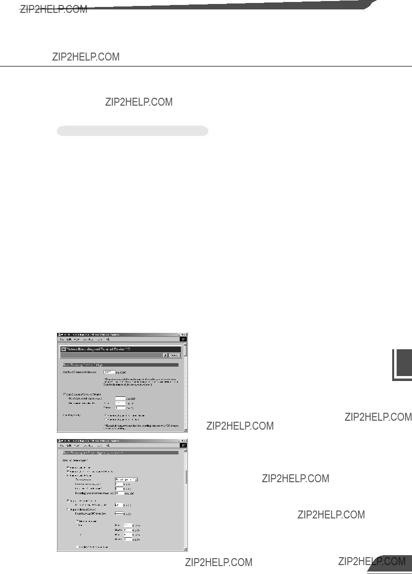
Using the Still Picture Recording Function Linked to an External Device
Sample Still Picture Recording Settings
Settings specified on the "Camera and Video" page (??? P.43)
Specify the appropriate settings for the Camera 1 being used.
Settings specified on the "Preset" page (??? P.47)
Set a camera angle that redords the open doorway as Preset 1.
Settings specified in "External Device Input 1/2" (??? P.48, 49)
???Set the recording time from 17:00 to 6:00.
???Give priority to "Recording triggerd by external device".
???Set the camera position for recording to Preset 1.
???Set the light to switch on when the door opens and to switch off 20 seconds after the door closes.
???Pictures are recorded 4 seconds before the door opens. The lights are not yet turned on.
???Record pictures for 8 seconds after the door closes.
???Record pictures at 10-second intevals while the door is open.
???Delete the recorded pictures at 12:00 on the next day. In this case, delete the pictures recorded in the morning at 12:00 on the next day, and delete the pictures recorded in the afternoon at 12:00 two days later.
6
Function Recording Picture the Using
Using the Still Picture Recording Function with a Predetermined Schedule
By using the "Schedule 1-4" setting, you can construct a monitoring system that records pictures according to a predetermined schedule. The still pictures captured in this way are recorded on a flash memory card inserted into the VB101.
Sample application in combination with a lighting unit
This is a monitoring system of the type used in art galleries and similar facilities in which the exhibits are monitored in the hours they are unattended. The light switches on and still pictures are captured at 10-minute intervals by a VC-C4R camera mounted on the ceiling. The equipment shown in the figure below is connected to the terminals on the rear of the VB101 at installation.
Installation Example
Lighting unit
In accordance with the predetermined schedule, Out1 is controlled from Out1 to switch on the lighting unit and pictures are captured and recorded by the camera.
Ethernet
VB101
Camera
VB101 Connection Example
V1 Video cable for the VC-C4R camera
 1
1
 2
2 
 1
1
 2
2 
In
CC1 Control cable for the VC-C4R camera
???Do not directly connect the power cord for the lighting unit to OUT1 or OUT2.
???Please confirm the Date and Time settings on page 39.
Using the Still Picture Recording Function with a Predetermined Schedule
Sample Still Picture Recording Settings
Settings specified on the "Camera and Video" page (??? P.43)
Specify the appropriate settings for the Camera 1 being used.
Settings specified on the "Preset" page (??? P.47)
Set a camera angle that records the exhibit as Preset 1.
Settings specified in "Schedule 1-4" (??? P.51)
???If you are not using recording triggered from an external device, leave the default priority ("Recording triggered by external device") unchanged.
???Set the camera position for recording to Preset 1.
???Insert a 5-second delay before recording to allow the camera to stabilize in the redording position.
???Set the light to switch on when recording begins and to switch off 10 seconds later.
???The recording time frame is from 20:00 to 06:50. Since recording occurs daily, set the recording start time from 0 to 6 and 20 to 23 every day of every month.
???Clear the "Apply the following repetition options at start time" selection.
???Delete the recorded pictures at 12:00 on the next day. In this case, delete the pictures recorded in the morning at 12:00 on the next day, and delete the pictures recorded in the afternoon at 12:00 two days later.
To select more than one, click
selections while holding down the
Ctrl key. (P.51)
6
Function Recording Picture the Using
Viewing and Distributing Recorded Pictures
You can search and view recorded pictures by accessing the "Sample Page for the Retrieval of Recorded Pictures". You can search by trigger, by camera or by time interval from your browser and view pictures as images or as a pseudo-animation. You can also distribute recorded pictures directly to users so that they can search and view the pictures in the same way.
Viewing Recorded Pictures
Use your Web browser to access the following
URL:
http://192.168.100.1/sample/lookup/
* Enter the actual IP address set for the VB101.
The "Sample Page for the Retrieval of Recorded Pictures" shown at left appears. Click the "Specify capture period with text" link if you want to enter numbers to specify the recording period to be searched, or click the "Specify capture period with menu" link to select the recording period from a menu.
When you select "Specify capture period with text", the Conditions for Image Retrieval screen appears in window  at left.
??? Select either "External Input" or "Schedule" as the "Trigger". External Input 1 and 2 correspond to the "External Device Input 1/2" parameter on page 49, and schedule 1-4 corresponds to the "Schedule 1-4" parameter on page 51. Use the "any" option to search all the options for the respective parameter.
??? In "Camera", specify the camera number to be searched. Select "any" to search all the cameras.
??? In "Capture Period", enter the date and time the pictures were captured.
Example 1/200004191830-20000420010530
Searches from 18:30:00 on April 19, 2000 to 01:05:30 on April 20, 2000.
Example 2/20000419-[blank]
Searches from 00:00:00 on April 19, 2000 to the present.
Example 3/[blank]-20000420
Searches from the oldest recorded pictures to 23:59:59 on April 20, 2000.
When you specify the search condition and click the [Retrieve] button, a list of the recorded dates and times that meet those conditions appears in window  . When you click on one of the listed items, the corresponding picture and camera settings appear in window
  .
.
Viewing and Distributing Recorded Pictures
If you select "Specify capture period with menu", the Conditions for Image Retrieval screen appears in window  at left.
??? Select either "External Input" or "Schedule" as the "Trigger". "External Input1 and 2 correspond to the "External Device Input 1/2" parameter on page 49, and schedule 1-4 corresponds to the "Schedule 1-4" parameter on page 51. Use the "any" option to search all the options for the respective parameter.
??? In "Camera", specify the camera number to be searched. Select "any" to search all the cameras.
??? In "Capture Period", select the date and time the pictures were recorded.
When you specify the search condition and click the [Retrieve] button, a list of the recorded dates and times that meet those conditions appears in window  . When you click on one of the listed items, the corresponding pictures and camera settings appear in window
  .
.
By clicking "Animation" in the list display, you can view all the retrieved pictures in the list continuously as a pseudo-animation.
6
Function Recording Picture the Using
123
Viewing and Distributing Recorded Pictures
Pictures Search CGI
The pictures search CGI includes the enum command to generate a list of recorded pictures that satisfy the search criteria, the desc command to generate the video data display page, and the data command to retrieve the video data.
enum Command
The enum command is used to generate a list display page for the search page and to generate a page for SnapAnimator. The items displayed in the recorded picture list generated by the enum command are displayed in order of the time they were recorded.
???enum Command Parameters
*1 This is a function that corresponds to address replacement using <_I_P_A_D_D_R_>.
However, you cannot specify <_I_P_A_D_D_R_> itself.
Viewing and Distributing Recorded Pictures
desc Command
The desc command is used to generate a video display page. The video display page uses HTML text for the video display area and attribute display area, and uses the data command described below to retrieve the video data.
???desc Command Parameters
data Command
The data command retrieves video data. The parameters only specify the video data and the format is the same as the b parameter for the desc command. Specify the data directly as "data?yyyymmdd/HHQQ/HHMMSSCC" with no parameter name. (QQ = every 15 minutes, indicated as 00, 15, 30, or 45.)
6
Function Recording Picture the Using

Viewing and Distributing Recorded Pictures
Distributing Recorded Pictures
Distributing pictures that have been recorded
If you forward a picture (JPEG) recorded with the Schedule recording function and copy it, or remove the card, download the picture to a PC and embed the picture in a Web page, you can create a still-picture distribution page.
Distributing pictures in SnapAnimator display format
Pseudo-animations (??? P.123) are created using the SnapAnimator applet. The following example is a SnapAnimator description in a HTML source. Customize the description between <APPLET> and </APPLET> to enter the picture in the place you want to paste it.
<APPLET CODEBASE="http://192.168.100.1/-wvdoc-01-/SnapAnimator/" code="SnapAnimator.class"
archive="SnapAnimator.zip" width=320 height=300> <PARAM NAME=cabbase VALUE="SnapAnimator.cab">
<PARAM NAME=image0 VALUE="http://192.168.100.1/-vbidb-/data?20000102/ 03040507">
<PARAM NAME=time0 VALUE="2000/01/02 03:04:05">
<PARAM NAME=image1 VALUE="http://192.168.100.1/-vbidb-/data?20000216/ 10100713">
<PARAM NAME=time1 VALUE="2000/02/16 10:10:07">
<PARAM NAME=image1 VALUE="http://192.168.100.1/-vbidb-/data?20000316/ 01100815">
<PARAM NAME=time2 VALUE="2000/03/16 01:08:15">
...
</APPLET>
* The underlined text is an IP address. Enter the actual IP address set for the VB101.
???SnapAnimator parameters
The above example was generated using an emum command for the picture search CGI. By using this description to properly specify the image0 and time0 parameters, you can also create an picture distribution page that displays any still pictures (JPEG) you have on hand as pseudo-animations. In this case, enter the time stamp that corresponds with the name of the picture file that you want to display in the shaded area and enter the imageX and timeX parameters for the number of pictures which you want to display.
Using VBCollector
VBCollector is used to view pictures recorded by the VB101. With VBCollector, you can collect and display still pictures recorded by the VB101 based on inputs from an external device or schedules. VBCollector accesses the VB101 at specific times expressed in units such as dates, weeks, or months, and then downloads the recorded pictures. Since the recorded pictures are saved one after another in the PC on which VBCollector is installed, pictures can still be securely saved when the allowable limit on the number of pictures that the VB101 can record and save has been exceeded. Downloaded images can also be easily viewed in the Web browser.
Flash memory card
Pictures periodically collected
according to the task
Pictures recorded with the VB101's
picture recording function
6
Function Recording Picture the Using
Downloaded image displays
Using VBCollector
Installing VBCollector
VBCollector requires that Microsoft Internet Explorer 5.0 or later be installed. c Before installing VBCollector, check to be sure that the correct version of
Note
Internet Explorer has been installed.
To Install...
1
If any other applications are running, please exit them before installation. Please also be sure to close the Windows Service Panel.
Load the supplied CD-ROM into the CD-ROM drive. Double-click ???CltSetup.exe??? on the CD-ROM to start up the installer. Click the Next button.
If you agree to the clauses in the licensing agreement, click Yes.
Specify the target directory for the installation and click the Next button.
If you have no special directory preference, just click Next.
4
Specify the menu name to be registered in the
Program menu of the Start button, then click Next.
Using VBCollector
Starting Up VBCollector
VBCollector is started up by choosing it from Start menu.
To Start Up VBCollector...
Choose [Program]-[WebView Livescope]-[VBCollector
Task View] from the Start menu to start up VBCollector.
Registering a Server
To use VBCollector, the network camera server (hereafter referred to as "server") from which the VBCollector downloads pictures must be registered.
Adding a server
Add a new server to which VBCollector will download pictures.
To Add a New Server...
1
To add a server, choose Add from the Server menu, or click the Add button on the Server List dialog box that appeared when Edit from the Server menu was selected.
Using VBCollector
2
Enter the various fields and click OK.
???Server Name
Assign a name for recognizing the Server.
???Image Directory
Enter the name of the directory where downloaded images are to be saved, or click Browse to select a directory folder. A network path cannot be specified.
[Delete images on the server]
When this check box is selected, pictures that VBCollector downloaded from the server will also be deleted from the server.
???Server information Host Name (??? P.38)
Specify an IP address or a host name.
HTTP Port (??? P.57)
Enter the HTTP port number set in the server. (The default setting is 80).
Administrator Account (??? P.38)
Enter an administrator account registered in the server.
Administrator Password (??? P.38)
Enter the administrator password registered in the server.
???Proxy
Use Proxy Server
Select if connecting through a proxy server.
Host Name
Specify a host name or IP address for the proxy server.
Port
Enter a port number for the proxy server (The default setting is 8080).
???PPP
Use PPP connection
Select if connection will be established by dialing up.
PPP Connection Name
Select a phone number from the phone book entry. A dialup network will need to have been installed and the phone number will need to have been registered in the phone book.
Account
Enter the PPP account to be used for the dialup connection.
Password
Enter the PPP password to be used for the dialup connection.
6
Function Recording Picture the Using
Using VBCollector
Editing Server Information
Content of the registered server information can be edited.
To Edit Server Information...
1
Choose Edit from the Server menu, and when the Server List dialog box appears, select the server name to be edited and click the Edit button.
To delete a registered server, click the Delete button.
2
As with the procedure for adding servers, change all desired items and click OK.
Registering Tasks
Adding a task
Add a new task for downloading images.
To Add a New Task...
1
To add a task, choose New Task from the Task
menu.
Using VBCollector
2
Enter the various items and click OK.
???Task Name
Assign the task a name.
[Enable this setting]
Select "Enable this setting" if the task is to be performed according to the schedule. If not selected, the added task will not be executed.
???Server Name
Select the server from which the VBCollector downloads recorded pictures. The server will need to have been registered in advance.
???Schedule Start Date
Set the date which is to be the starting point of the schedule. The task will be executed after the specified start date according to the criteria specified below.
Start Time
Set the time when the task is to start up (in 24-hour format).
Once
Select if the task is to be executed only once. The task will be executed only once at the start time on the start date.
Daily
Select if the task is to be executed once every certain number of days. This number of days can be specified between 1 and 31.
Weekly
Select if the task is to be executed every certain number of weeks on a certain day of the week. Set the number of weeks between 1 and 53, and specify the day of the week.
Monthly
Select if the task is to be executed every month on a certain day of the month. Set this day between 1 and
31. Or a day of the week for a certain week of the month can also be specified.
???Details Repeat task
Select if task is to be executed in repetition in time units. Downloads occur in repetition only for the specified number of times at specified intervals starting from the Start Time specified in the schedule. If not selected, download occurs once at the start time specified in the schedule. If Repeat task has been set, the first download, which occurs at the start time, is not counted in the number of repetitions. The number of downloads to occur every certain number of hours can both be specified. Set the number of hours to a value between 1 and 23, and the number of downloads to a value between 1 and 23.
Retry when an error occurs
Select this item if a task is to be executed again in the event a download does not end normally after a task is executed. The task will be executed again a specified number of times at specified time intervals. During this time, if the download is completed normally, further tasks will not be repeated. Specify the number of times and the time interval at which a task is to be re-executed. For the number of times, enter a value between 1 and 10; for the interval, enter a value between 1 and 10.
Disconnect after finishing download (for access via dial-up connections)
If the connection with the server is a dialup connection, when this item is selected, it will automatically be disconnected when the task ends.
6
Function Recording Picture the Using
Up to 16 tasks can be executed by VBCollector simultaneously. Please be sure not to load a schedule with 17 or more tasks to be executed. VBCollector is also not able to execute multiple tasks simultaneously to the same server. Please take care to ensure that multiple tasks are not executed to the same server by taking such measures as leaving a sufficient time space between the ???Start Time??? of each task.
Editing Tasks
The details of a registered task can be edited.
In the Task View, select the task to be edited by clicking on its name, then choose Edit Task from the Task menu. Or, double-click on the task to be edited. To delete a registered task, choose Delete Task from the Task menu.
Executing and Canceling Tasks
Executing a task
Registered tasks are executed automatically according to predetermined schedule when "Enable this setting" is selected at Task Settings. If you want a task to be executed immediately, select the desired task on the Task View and choose Execute now from the Task menu.
Using VBCollector
Canceling a task
To disable a registered task, clear "Enable this setting" at Task Settings. To abort the execution of a task, in the Task View, click on the task to be aborted, and choose Abort in the Task menu.
Details Displayed on the Task View
The execution status can be checked on the Task View.
???Task Name
The names that were specified at Task Settings are displayed here. The status of each task is displayed as an icon at the left of the name.
???Server Name
The server names that were specified at Task Settings are displayed here.
???Next Run Time
The date and time when the task is to be executed next is displayed here.
???Last Result
The last results achieved by the task and the task end time are displayed here.
???Schedule
The start date, start time, and execution interval for each task are displayed here.
6
Function Recording Picture the Using
Using VBCollector
Refreshing Task View Display Content
To update the Task View content to reflect the most recent information, choose Refresh from the View menu.
Starting/Stopping the Service
The task scheduler service can be started and stopped.
Choose Start Service or Stop Service from the Tools menu. If the service has started, Stop Service is enabled in the menu; if the service is stopped, Start Service is enabled.
Using VBCollector
4
HTML for displaying the images is generated, the Web browser starts up, and thumbnail images of the selected date are displayed in 100-image units on the page. Click on the image to be viewed; it is displayed in the original saved dimensions.
5
When Detail Information above the frame is clicked, detailed information on the images in the thumbnail screen is displayed. Click on the image to be viewed; it is displayed in the original saved dimensions.
Deleting Images
Downloaded images can be deleted.
To Delete Images...
Choose Delete Image from the Tools menu. In the Image List dialog box, select the name of the server that the VBCollector downloaded the images to be deleted, select the date to be deleted by clicking on it, then click the Delete Image button.
Using VBCollector
Displaying logs according to selection criteria
Logs can be filtered according to type, code, or date and time so that only the required information is displayed.
To Set Display Criteria...
Choose Filter from the View menu.
The Filter dialog box appears. To display only the logs that match the specified criteria, enter the criteria below and click OK. If no changes are required, click Cancel.
[Specify Task.]
Select if filtering by task name, then enter the task name. [Specify Server.]
Select if filtering by server name, then enter the server name. [Error Type]
Specify the error type when filtering by error type.
???Not Specified
Selecting this item disables priority and code settings.
???Specify Priority.
From Error, Warning, or Information, select the error level to be displayed.
???Specify Code.
Select if only logs with the corresponding identification code are to be displayed, then enter the identification code.
[Date & Time]
Filters logs by output date and time.
???Specify Start Date & Time.
When this item is selected and a date and time is entered, logs generated after the specified start date and time are displayed.
???Specify End Date & Time.
When this item is selected and a date and time is entered, logs generated before the specified end date and time are displayed.
 Chapter 7
Troubleshooting
This chapter explains how to deal with problems that arise with the
operation of the VB101 and other faults.
Troubleshooting
Before you contact your Canon dealer or service outlet, check the items listed below. If a log message is displayed, refer to the log message list for the log details and the appropriate response.
The VB101 does not start up. The Power lamp does not light.
???Check that the AC cable is connected correctly. (??? P.25)
???Switch the VB101 off and then on again (??? P.24).
???If initial settings (see p. 33) have not been made, the Power LED illuminates in orange, but this does not indicate a malfunction. Please make the initial settings.
???If the Power LED stays orange and does not change to green, this indicates that there is a system fault. Restore the factory default settings (??? P.160). If this does not resolve the problem, contact your Canon dealer.
The initial setup tools do not work.
???Check that the RS-232C cable used for setup is connected correctly. (??? P.25)
???Check that you have selected the correct COM port. (??? P.33)
???Check that there are no other active applications (terminal software, etc.) that are using the COM port.
I cannot access the VB101 over the network.
???Check that the LAN cable is connected correctly. (??? P.25)
???Check that the VB101 network settings are correct. In particular, check that the IP address, subnet mask and default gateway address settings are valid for the network you are using. (??? P.33, 38)
???If you have changed the IP address, the new IP address does not take effect until you reboot the VB101. Be sure to restart the VB101 after changing settings.
???If access control for the VB101 is being used, check the settings (??? P.52).
???Check that the IP address or URL settings in the viewer software are correct.
???If the NAT function of the router is used, check that the VB101's IP address noted on the Web page is correct.
The video does not appear.
???Check that the camera is switched on and that the video cable is connected correctly.
???If the video quality is poor, check the video quality settings on the VB101 (??? P.43). Also, check settings such as the number of background colors as on the viewer PC.
???You can limit the number of viewers that can access the VB101 at the same time (??? P.55). The message without video is displayed when this limit is exceeded.
???If you cannot see the video using the Java Viewer, check system settings such as the browser version (??? P.18). Up-to-date information is provided on the VB101 Website. (URL: http://www.canon.com/webview/)
???To view video using the Helper Viewer, it must first be installed (see p. 16). Please install Helper Viewer after confirming the operating environment (see p. 18).
144
Log Messages
The Syslog log messages are classified into the following 5 categories. Classification details are dealt with in the UNIX syslog and the levels are explained in Chapter 3 (???P.58).
* The syslog facility is local7.
Log Messages for Applications
???A002 Protocol initialization failure (err)
???A004 Fault in initial video input systems settings (warning)
???A005 Camera control channel assignment error (warning)
???A006 Camera control system initialization failure (err)
146
Log Messages
???A016 Amount of transmitted video data (info)
???A022 Applet archive load failure (warning)
???A023 Status change of external input devices (err)
???A024 Picture recording suspended and restarted (notice)
Log Messages
???A033 Invalid file detected during picture index restoration (info)
???A034 Recorded picture file read error during picture index restoration (info)
HTTP Server Log Messages
???H011 File specification error (notice)
Card Slot-related Log Messages
???P001 File system mounting failure (warning)
Log Messages
System-related Log Messages
???S001 Ethernet interface initialization failed (crit)
???S002 Ethernet route registration failure (err)
???S003 Ethernet default route registration failed (err)
???S006 IP address conflict detection at startup (err)
Log Messages
???S015 Root directory entry count error (err)
???S016 Logical sector size error (err)
???S018 Write error during file system checking (err)
???S021 File system structural defect (err)
154

Specifications
External Device I/O Terminals
External Device Input Terminals (In1, In2)
The external device input terminals consist of 2 terminals (In1 and In2), one of which is '+' (red) and another is '-' (black). The '-' terminal is grounded on the inside of the main unit. By connecting two cables to the + and ??? terminals and then electrically short-circuiting across the terminals (ON) or separating the connection (OFF), an interrupt can be generated for the internal controller. See "Picture Recording and External Device I/O Settings Page" in Chapter 3 "Setup Procedures" (??? P.49) for information on the settings.
Connect any sensors and switches to terminals with electrically separate GND terminals and power supplies.
External Device Output Terminals (Out1, Out2)
The external device output terminals consist of 2 white terminals (Out1 and Out2). Both terminal combinations are peers. The Internal controller switches the two output terminals to disconnected or connected condition. The output terminals use optocouplers and are separate from the internal circuit in the VB101. Loads connected to the output terminals should be within the following ratings:

Using the Enclosed Software
Restoring the Factory Default Settings
Use the "IniVB101.exe" and "inivb101.elf" files in the same directory on the enclosed CD-ROM to
restore the VB101 settings to the factory default values.
1Select direct connection to COM1 as the connection method.
???On some PCs you may have to select a port other than COM1. Check the port number to which the serial cable is connected.
2 Switch the VB101 off and then on again.
3 Enter the password (the default setting is "VB101").
??? When you switch the VB101 on again, the [Next] button is enabled.
4 When the confirmation message appears, click the [OK] button.
???The factory default setting are restored
???Refer to P.162 for the factory default settings.
???When you click the [Cancel] button after switching the VB101 back on, the c power LED remains lit orange. At this point, the VB101 software has not
???If you forget the password, you will have to return the VB101 to a service center. Please contact your Canon dealer.
Using the Enclosed Software
Upgrading the Firmware Remotely
When a new version of the firmware is released, the firmware can be upgraded remotely. To upgrade remotely, use the "vbrfu.exe" program on the CD-ROM and the new firmware.
1Enter the IP address, user name and password.
???Server Address: Camera server IP address
???HTTP Port : The HTTP port No. of the camera server (Default setting = 80)
???Administrator Name: Server administrator user name
???Administrator Password: Server administrator password
2 The current version is displayed.
3 Specify the firmware file to be downloaded to the server.
4 Store the downloaded firmware in flash ROM.
(5) The completion window appears.
Appendix


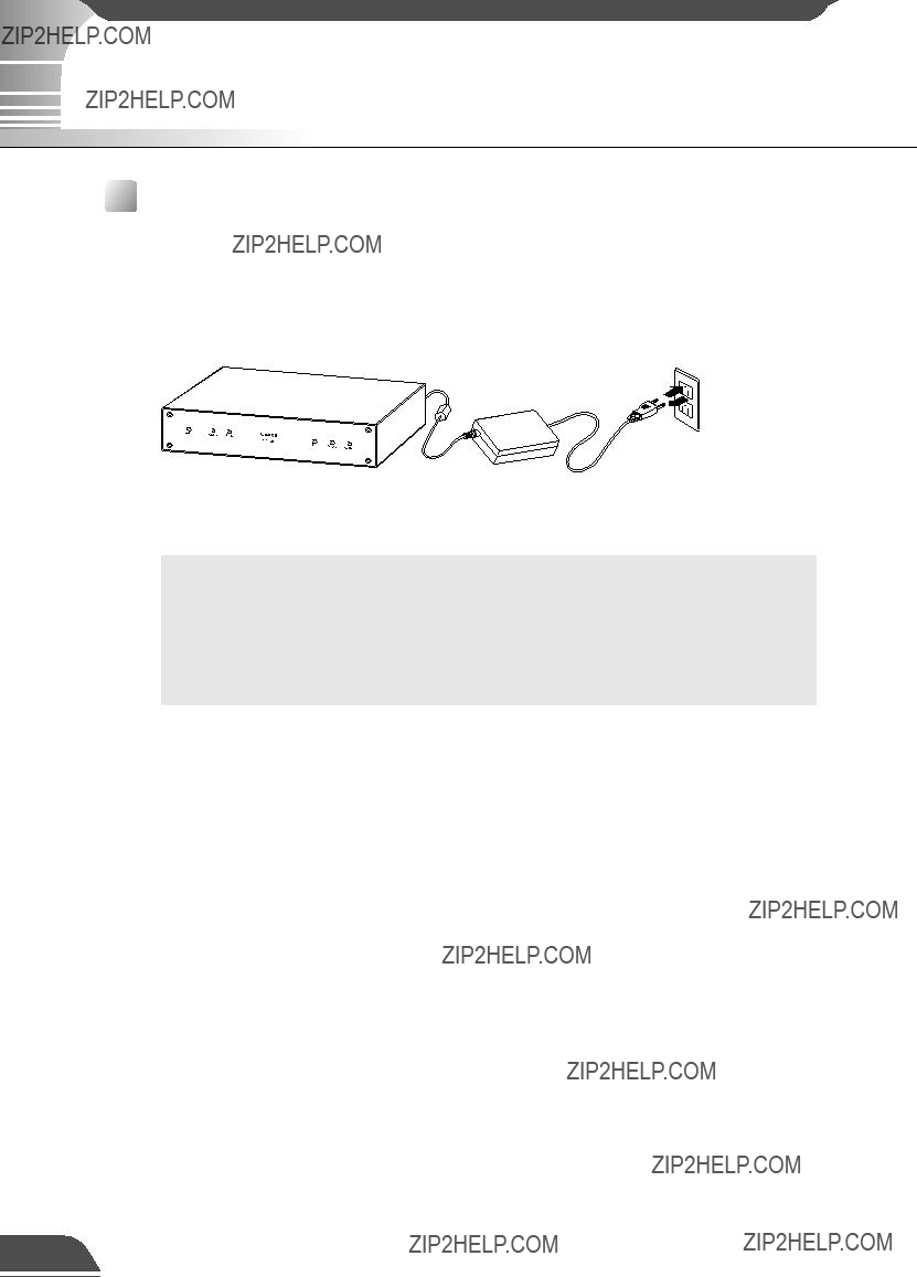


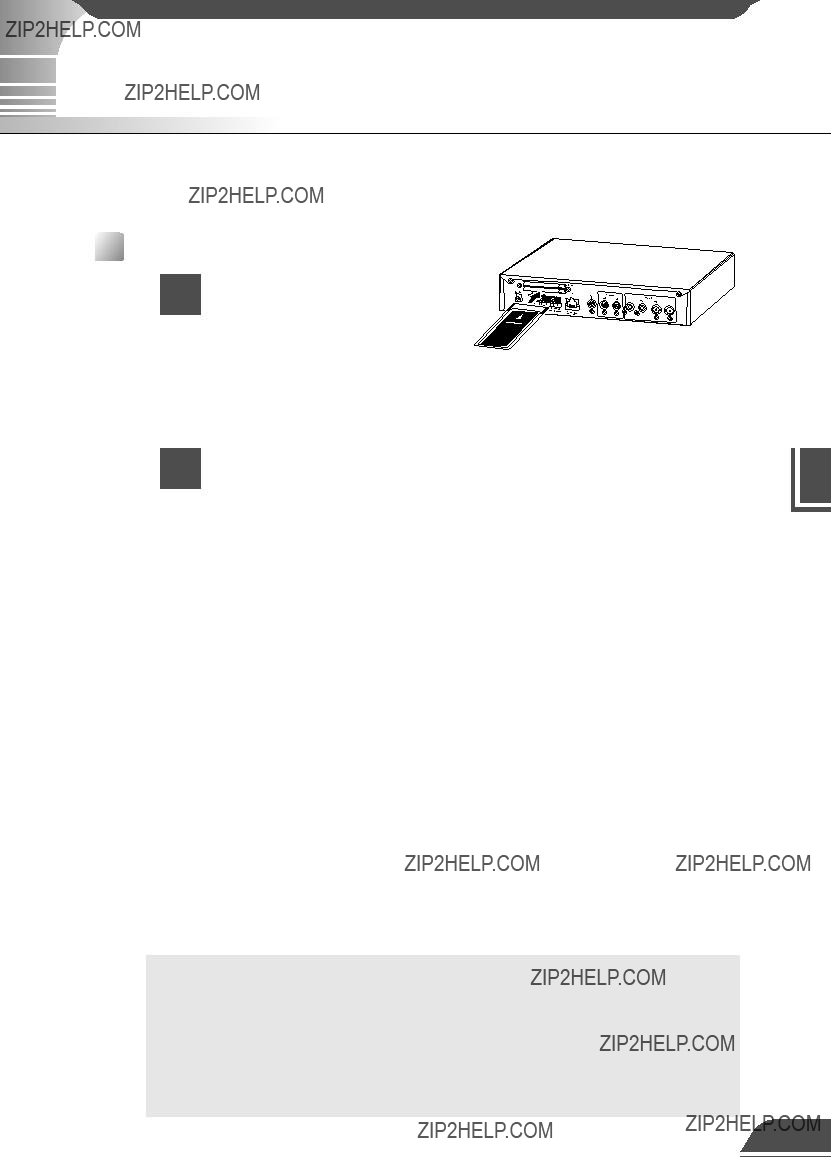


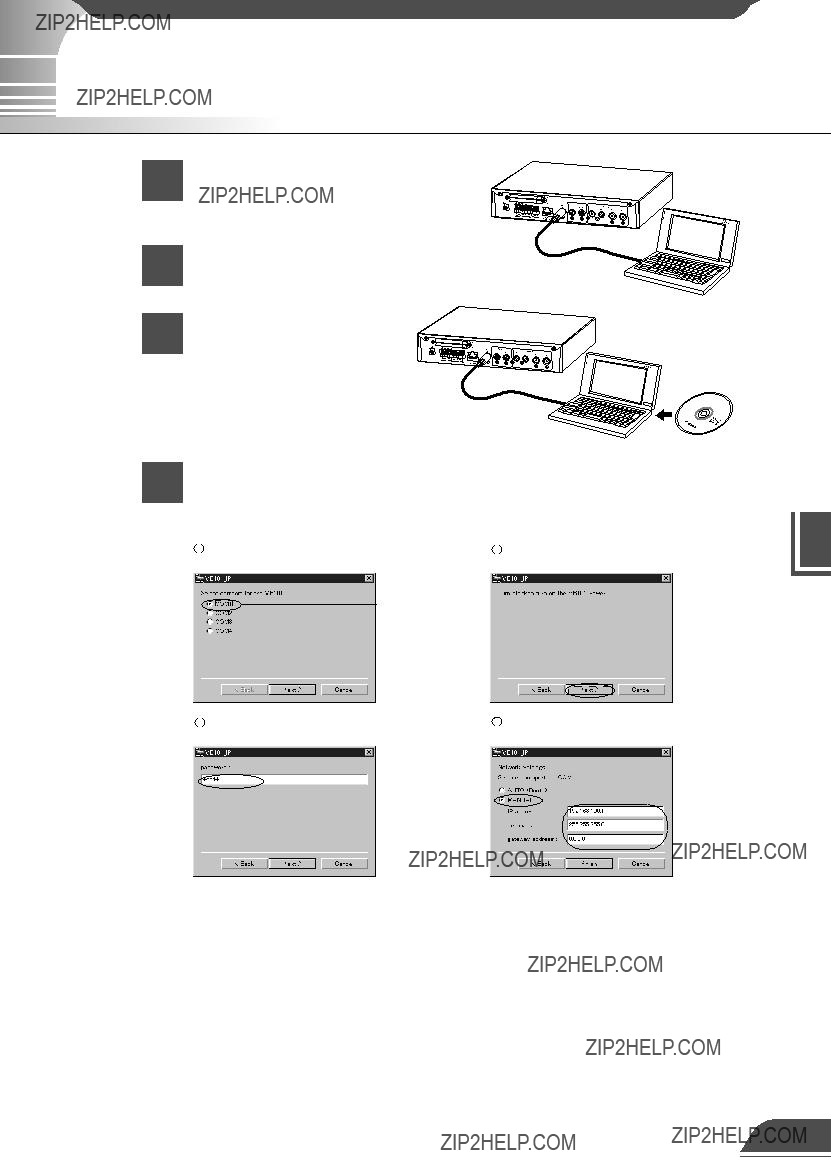
 to
to  below to enter the password, IP address (192.168.100.1 is


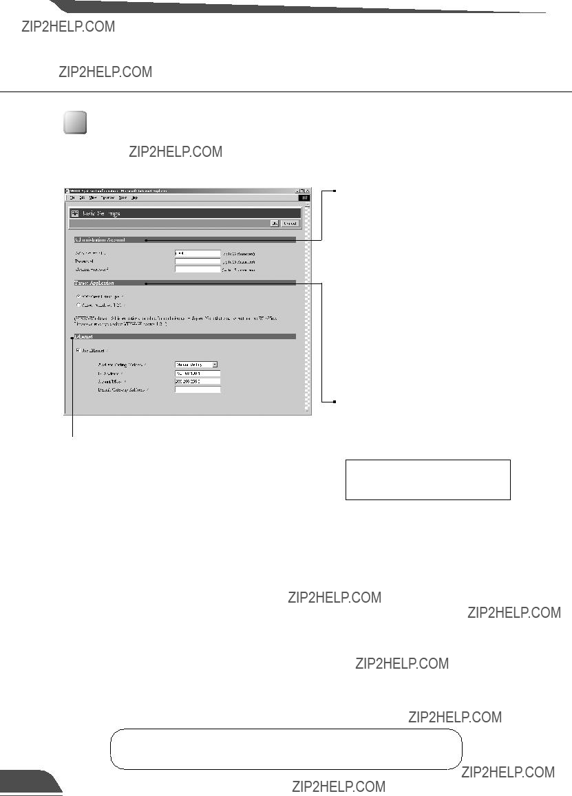


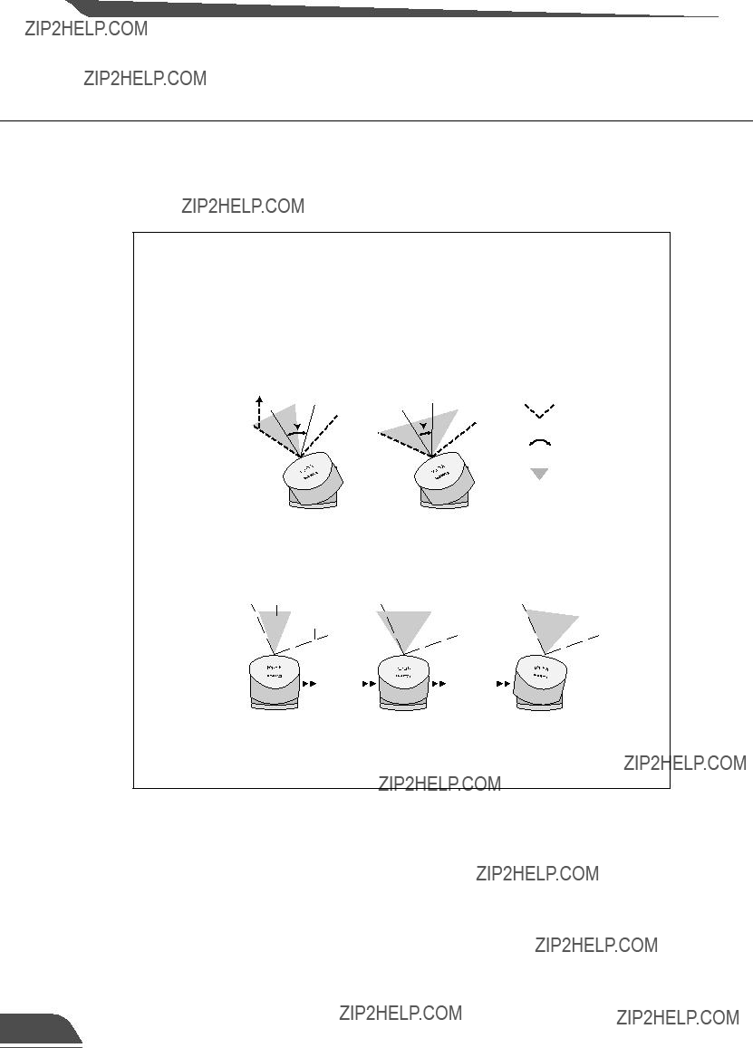

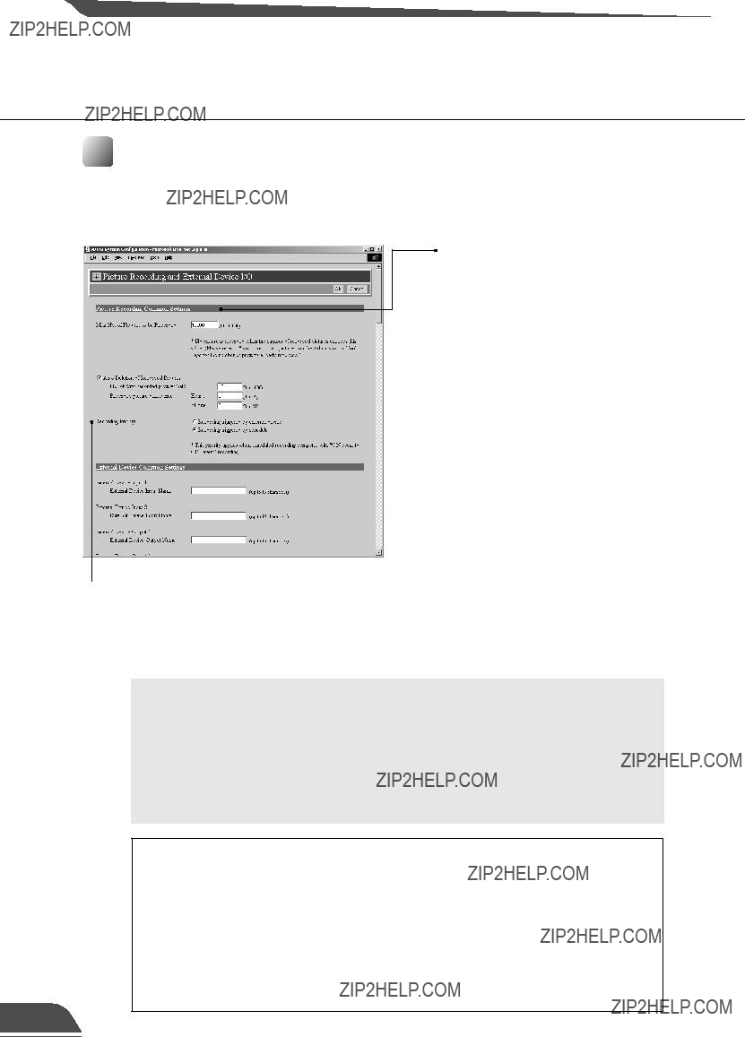
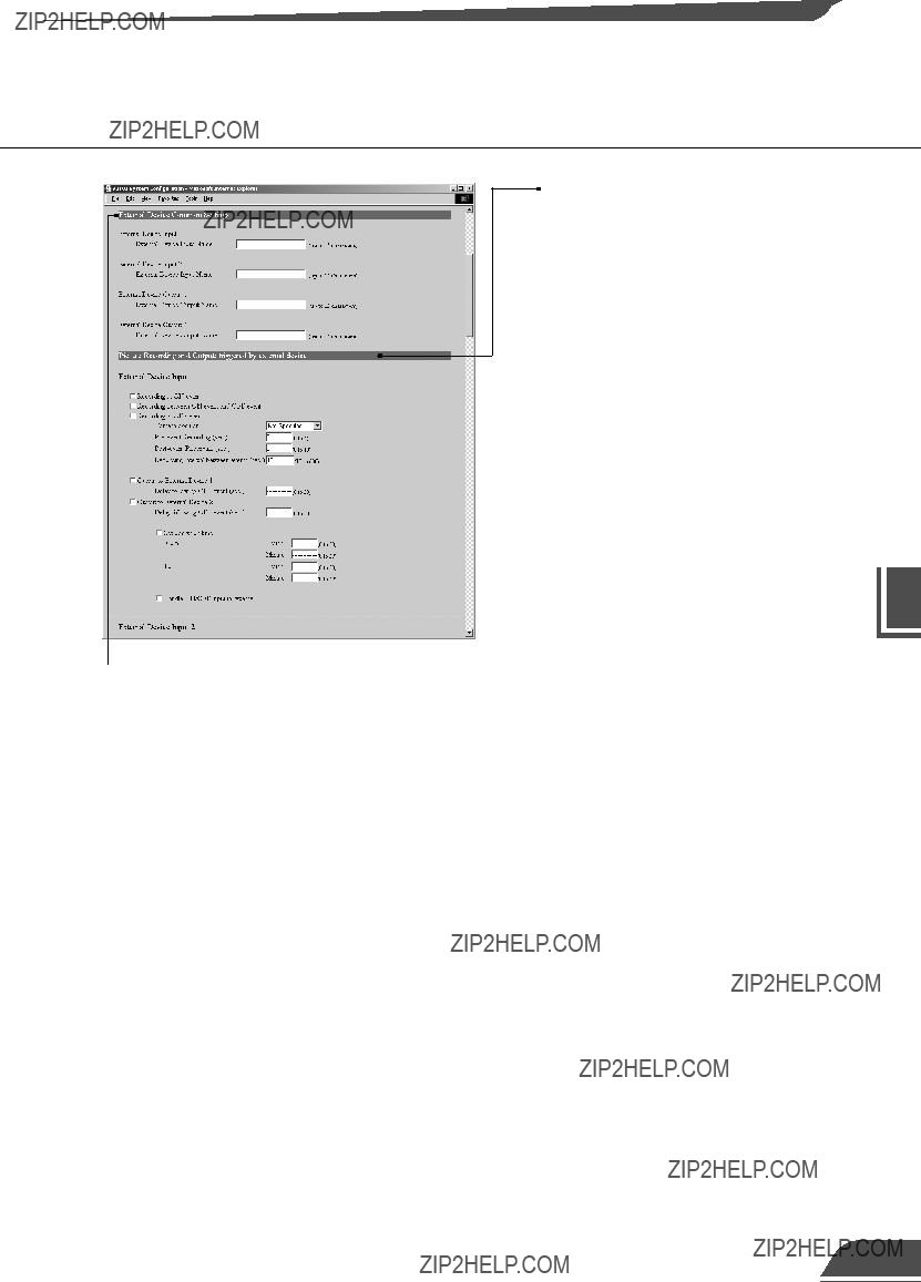
 External device common settings


 Mail
Mail Enter the addresses from the top down. If you are only registering 1 or 2 addresses, the remaining fields can be left blank.


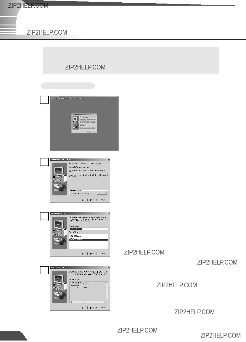

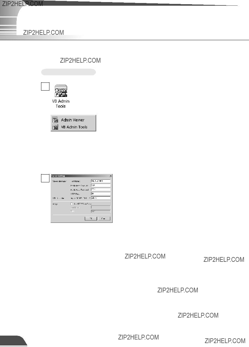
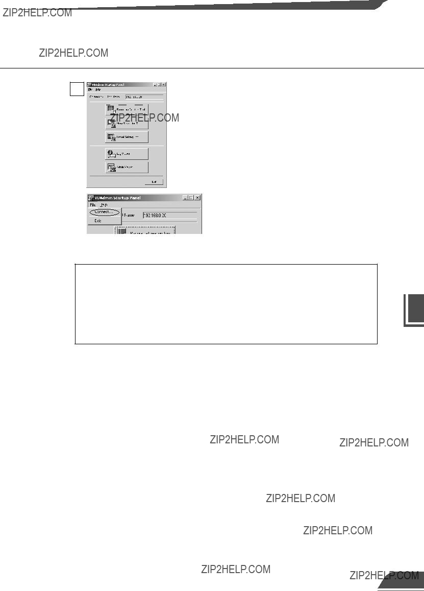


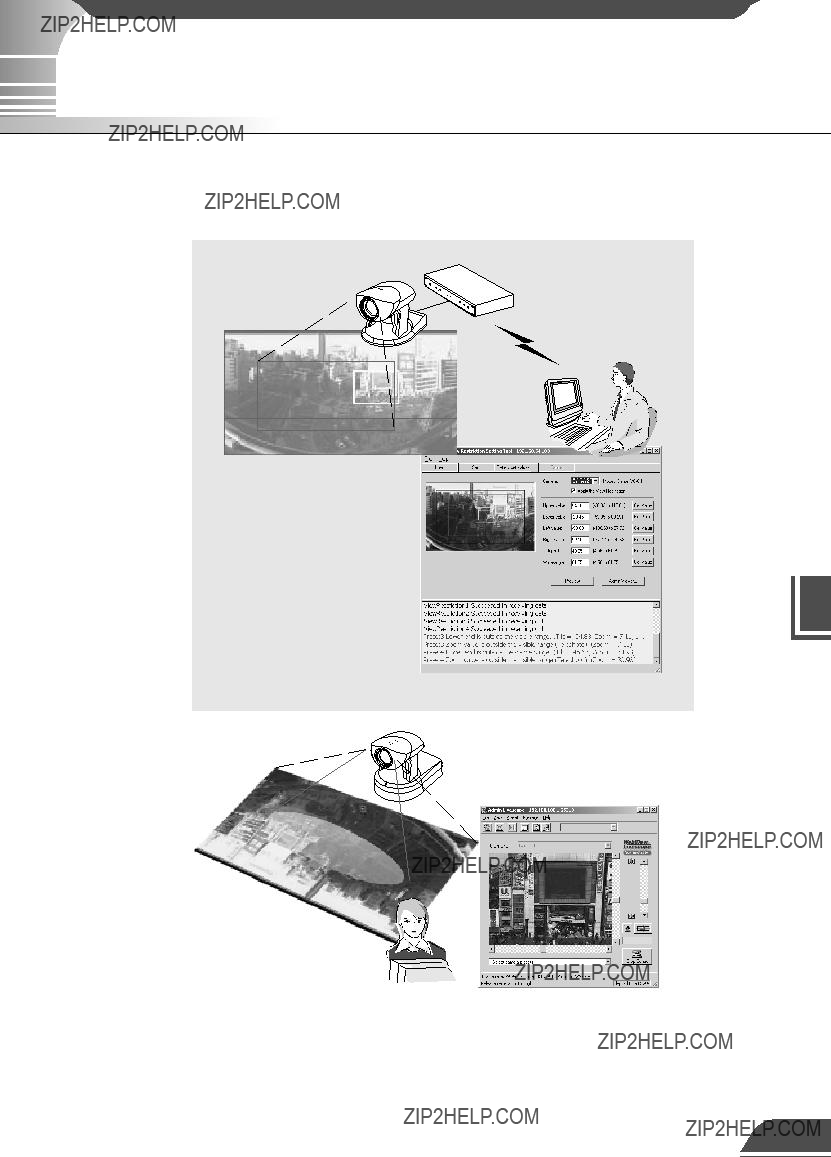


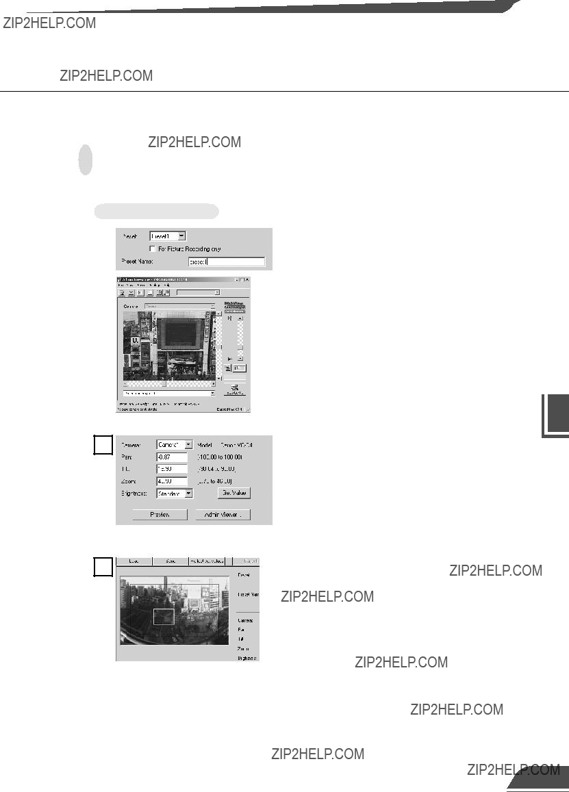

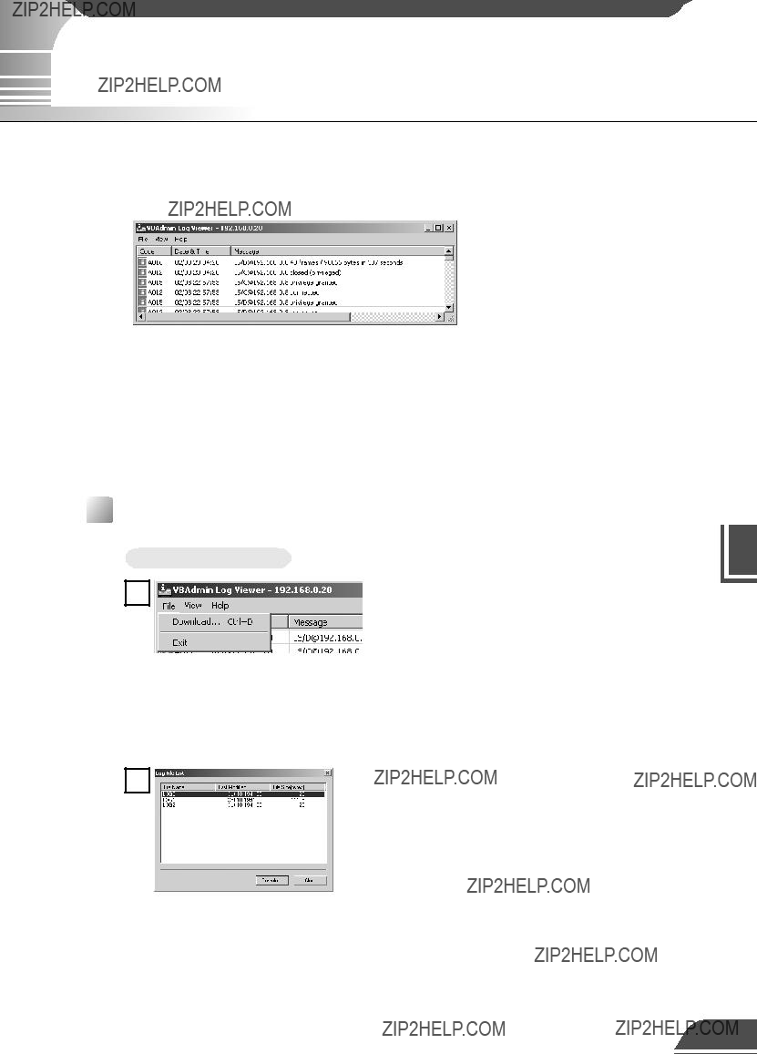


 , a file that includes the IP address information for the VB101 is sent from the Web server in step
  . If you are using the Java version, the applet is downloaded to the viewer PC from the VB101 in response to the request in step
  and the video request is then initiated.
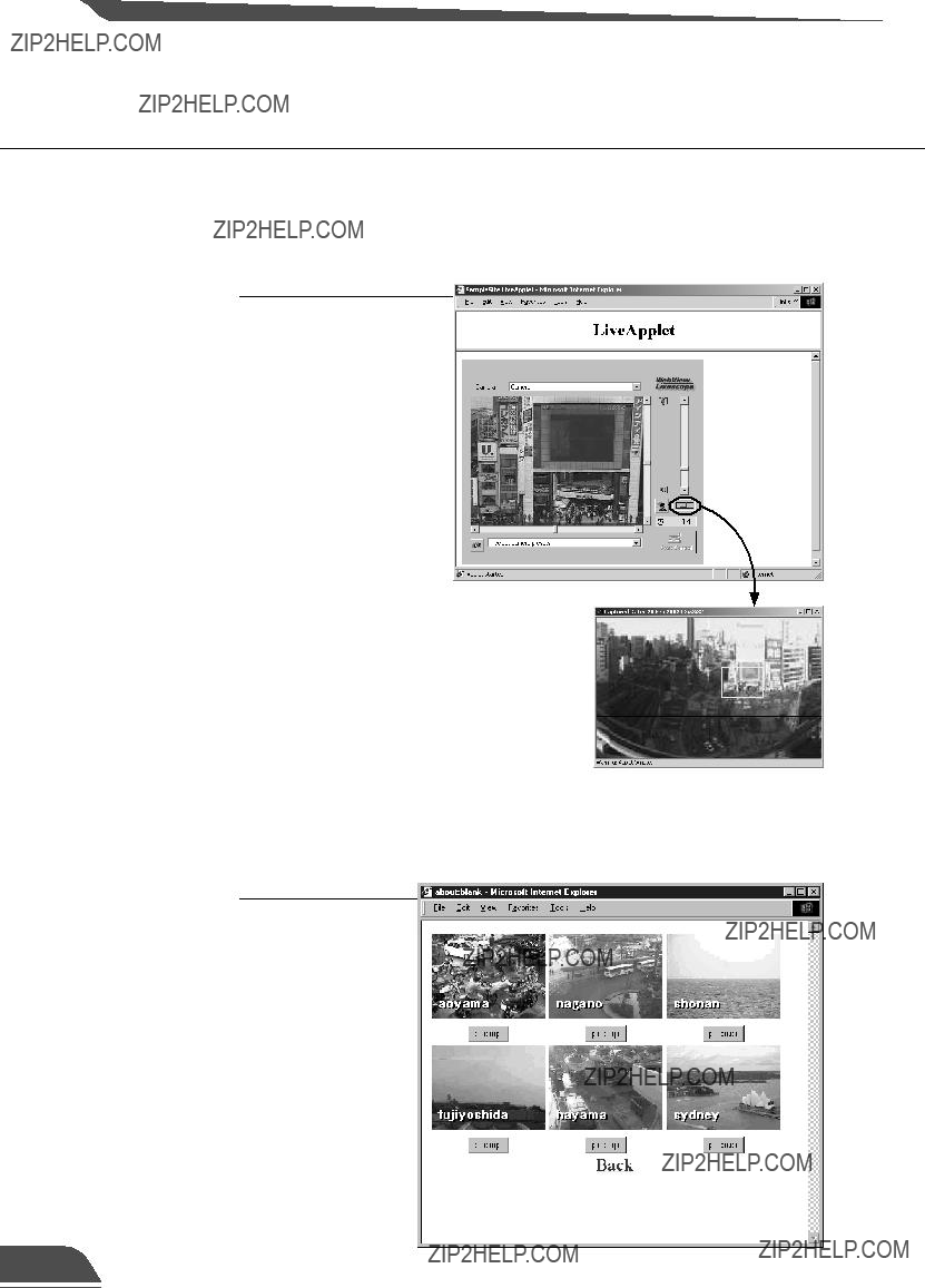


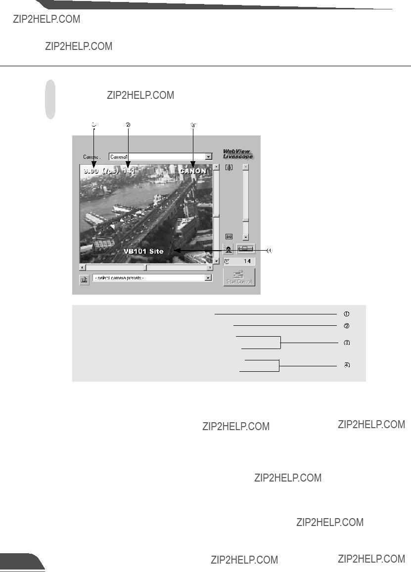
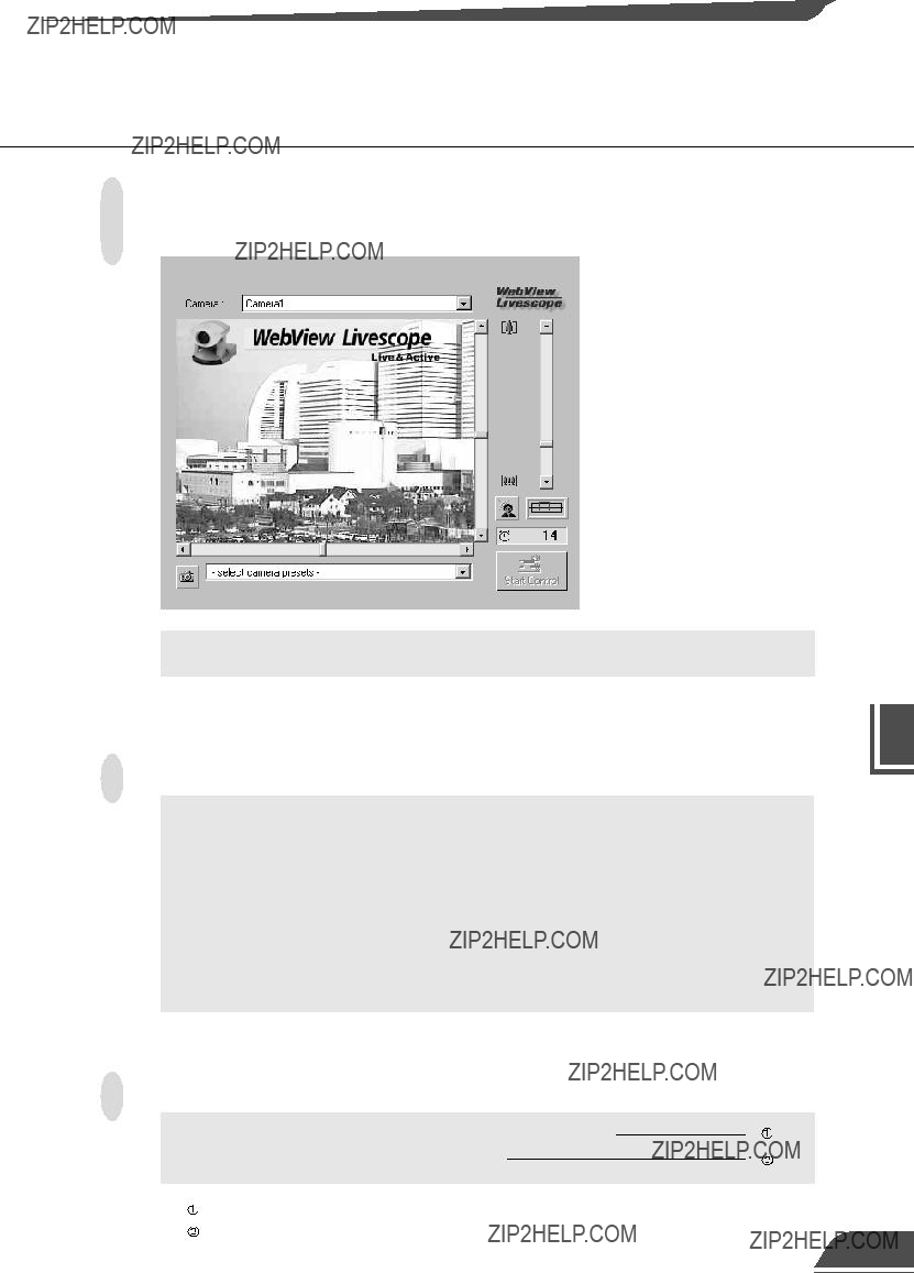


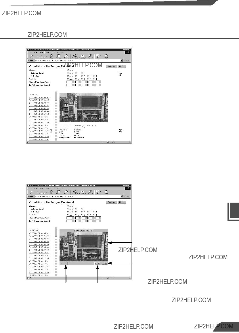


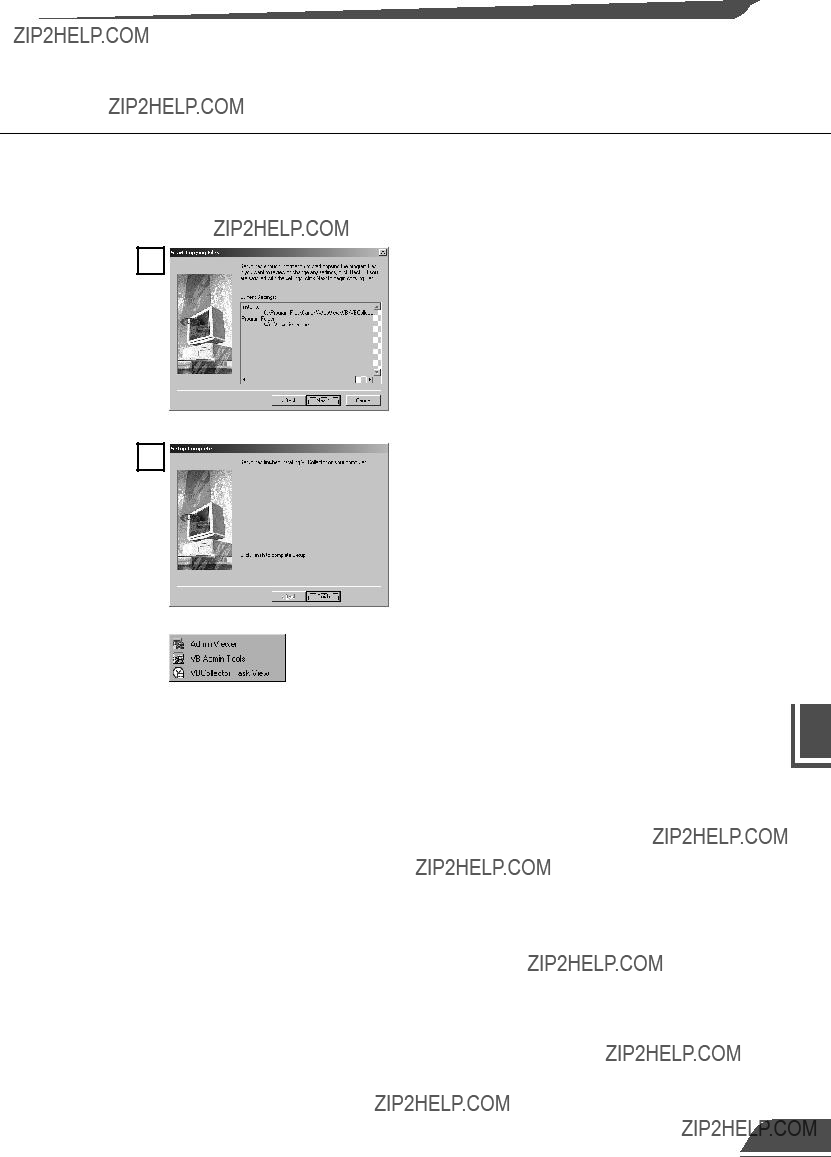


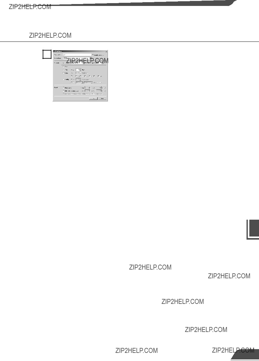

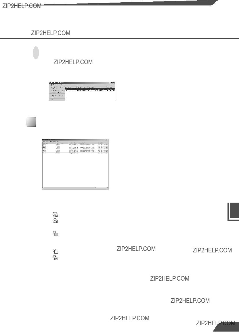


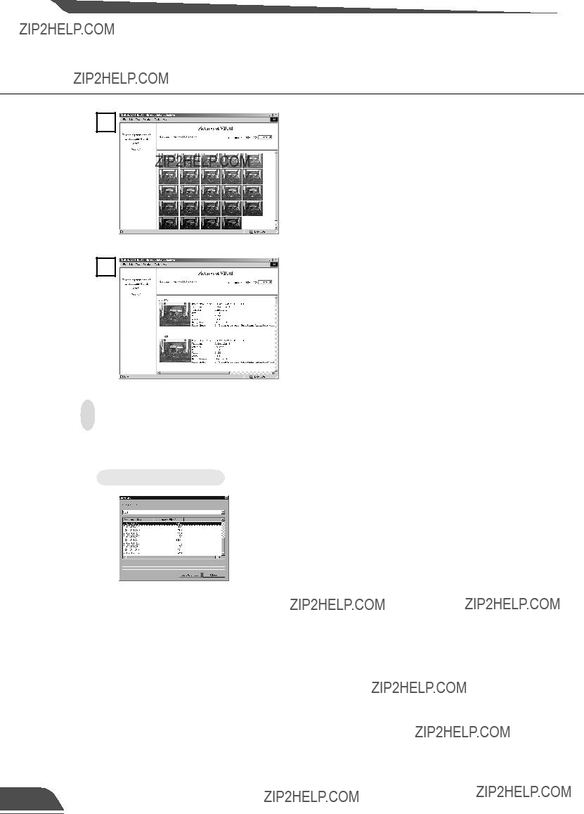

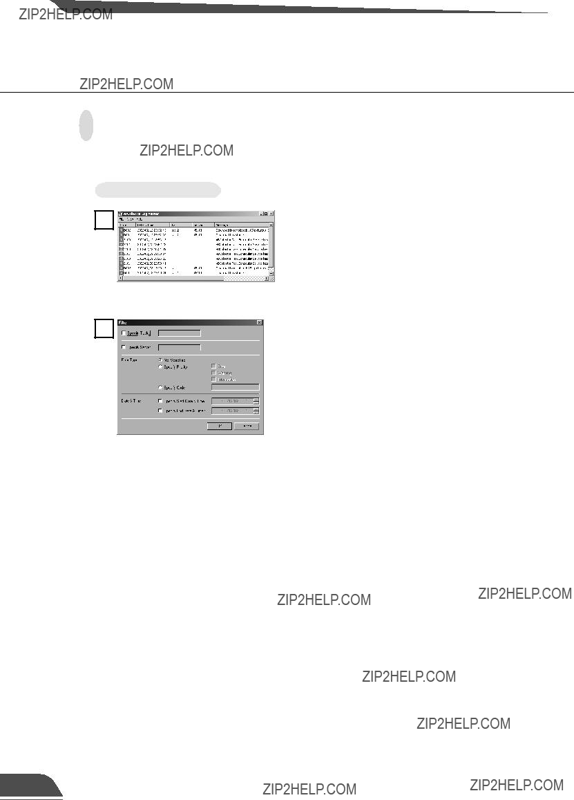


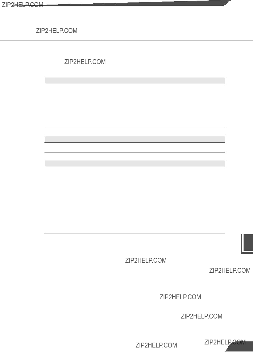


 Appendix