Thank you for purchasing the Canon Network Camera VB-C10/VB-C10R (referred to hereafter as the VB-C10/VB-C10R).
This manual describes how to set up and use the VB-C10/VB-C10R. Read this manual carefully before using the VB-C10/VB-C10R to ensure effective operation. In particular make sure that you read the "a Safe Use of Equipment" in this manual, as well as the supplied CD-ROM Readme file.
Exclusion of Liability
If the Product is connected to a recording device (for example a VCR), Canon Inc. accepts no responsibility whatsoever for any financial losses that may be incurred as a result of the loss of recorded information or images, regardless of the internal or external cause of the loss.
Copyright Information
Video or still pictures recorded using your VB-C10/VB-C10R cannot be used in ways that infringe copyright laws or without the consent of the owner, unless intended for personal use only.
Notes
1.The unauthorized transfer of all or any part of the contents of this Manual is forbidden.
2.The contents of this Manual are subject to change without notice.
3.Every effort has been made to ensure that this Manual is flawless. However, if you find any oversights, please let us know.
4.Item 3. notwithstanding, Canon accepts no responsibility for any effects resulting from the use of this Manual.
Trademark Notices
???Canon and Canon logo are registered trademarks of Canon Inc.
???Microsoft and Windows are registered trademarks of Microsoft Corporation in the United States and other countries.
???Windows is legally recognized as Microsoft Windows Operating System.
???Other brand or product names in this manual may be trademarks or registered trademarks of their respective companies.
???This product uses Linux kernel, gcc-libs, readline, init, sftpd, net-tools, mactool, telnetd, syslogd and boa under license of GNU General Public License (GPL); glibc and termcap under license of GNU Lesser General Public License (LGPL); and ash, sh and ping under license of modified BSD License.
Documents of Linux kernel COPYING, GPL, LGPL, and modified BSD License are stored as the files of COPYING.txt, GPL.txt, LGPL.txt and mBSD.txt respectively within LICENSE folder of accompanied CD rom with the package.
If you (customer) need program source codes under the terms and conditions of GPL and/or LGPL, please access
http://www.canon.com/webview/webview-tech/


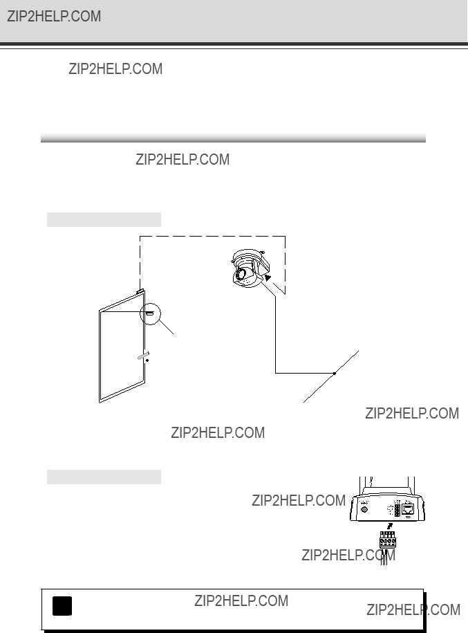
 External device I/O terminals
 Power connection socket
 100/10 BT Ethernet connector


 Screw
Screw


 AC adapter
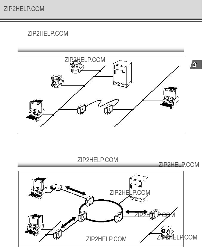


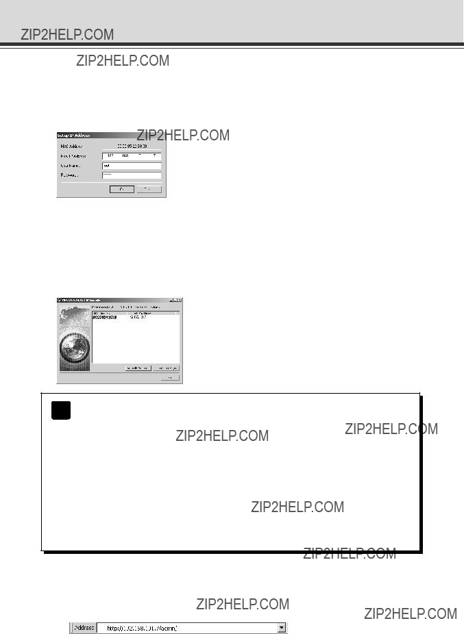
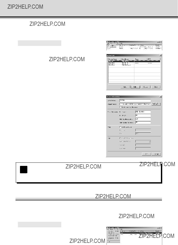
 The values shown here are examples only.*
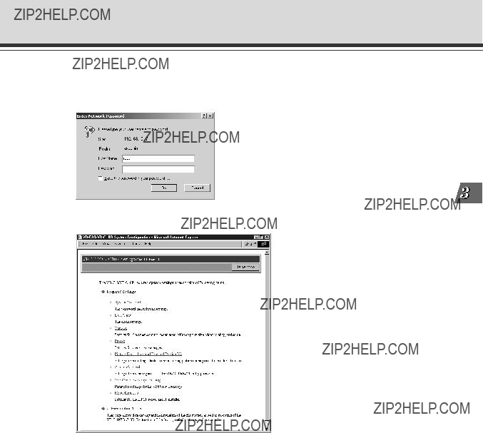
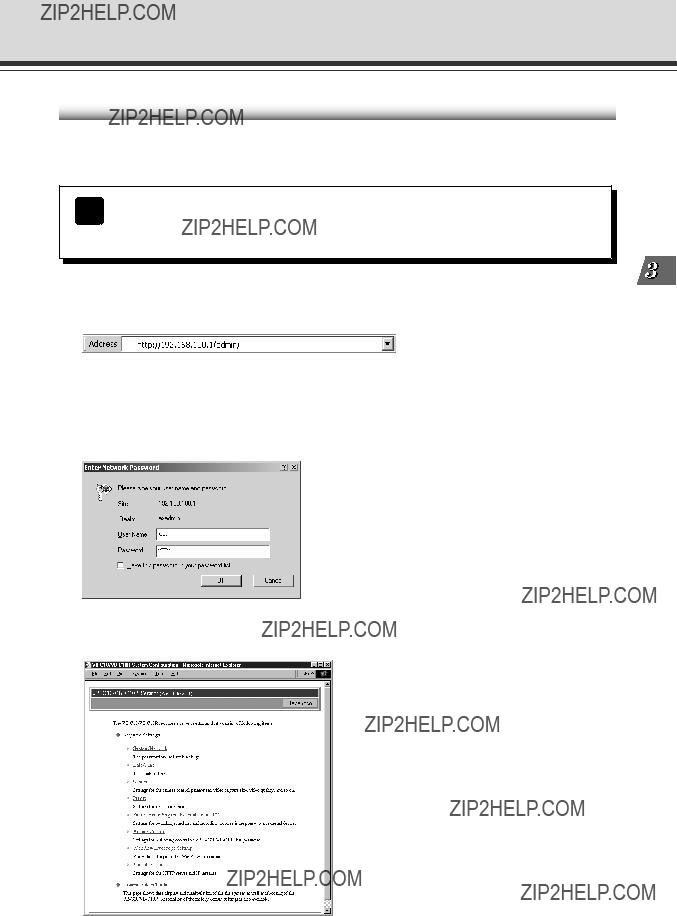


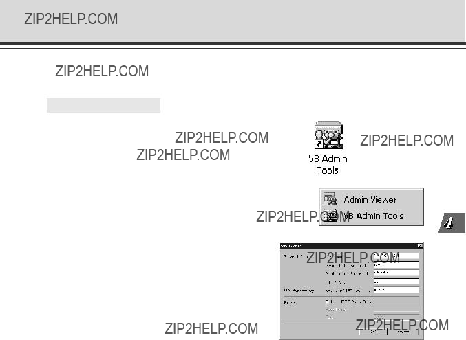
 ???Japanese??? button
 Clicking on the titles displays each setting pages.
 Root Account
 Ethernet
 Date and Time
 Camera Settings
 ???View Restriction???
 ???Home Position???

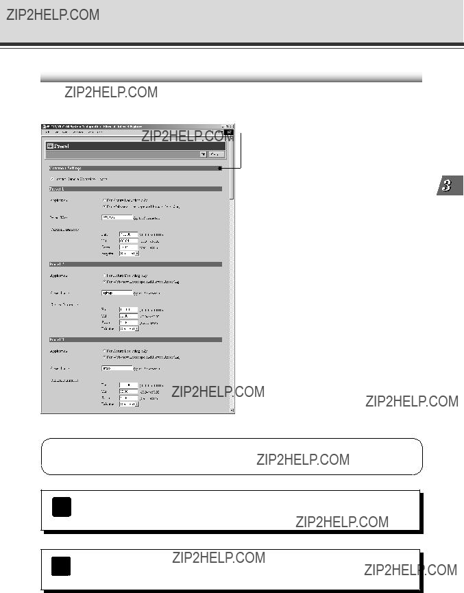
 Common Settings
 Presets

 External Device Input

 Schedule
 External Device Names

 Authorized User Account
 ???Restrict Service Time???
 WebView Livescope
 HTTP Server
 Connection Keeping
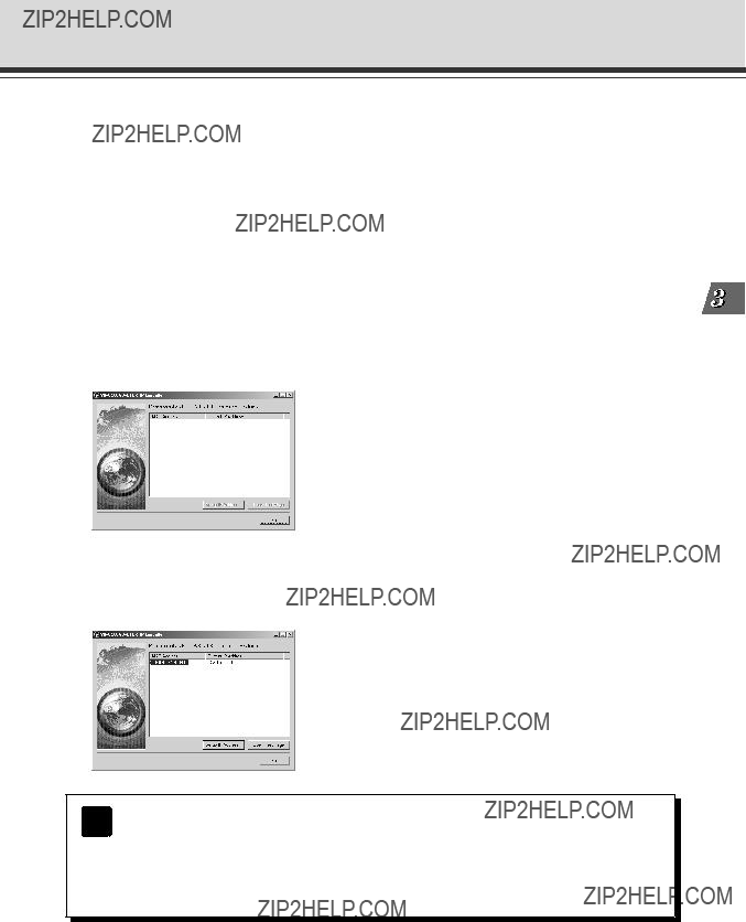
 IP Installer

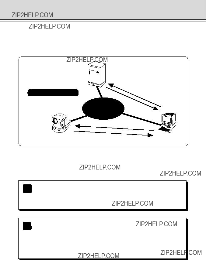
 ISDN/leased line/
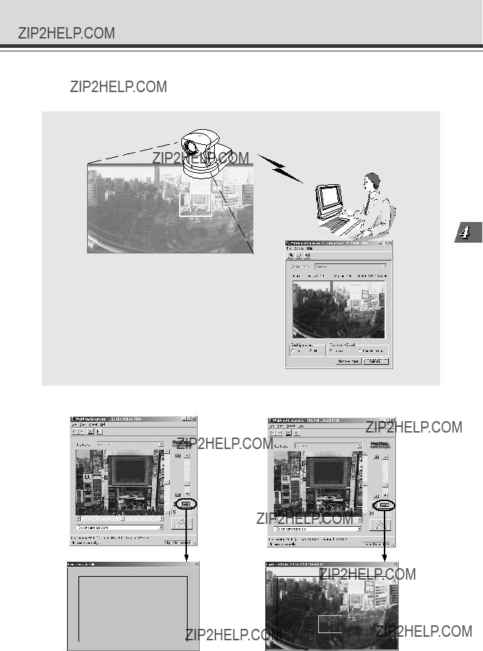
 VB-C10/VB-C10R
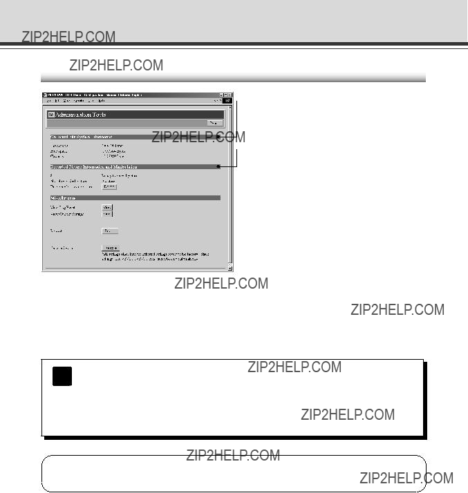

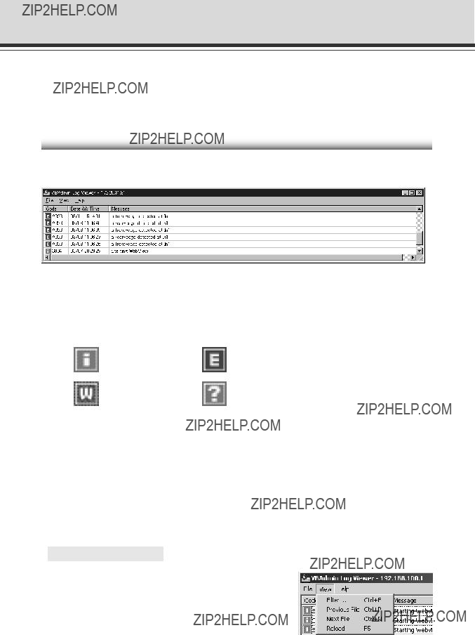
 Recorded Picture Information and Manipulation
 Miscellaneous

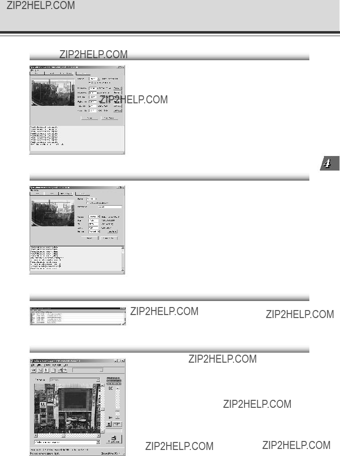


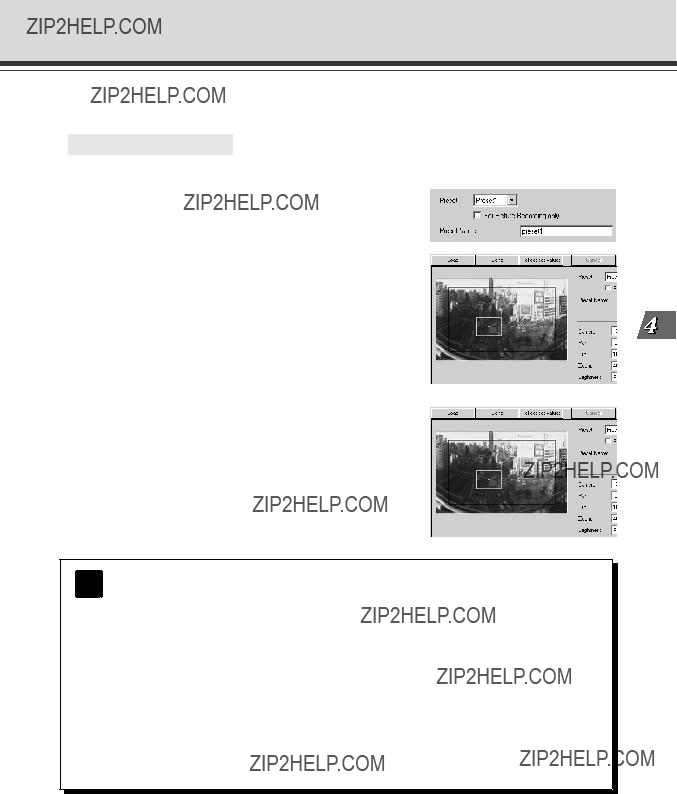


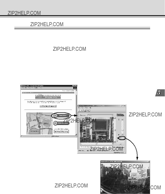


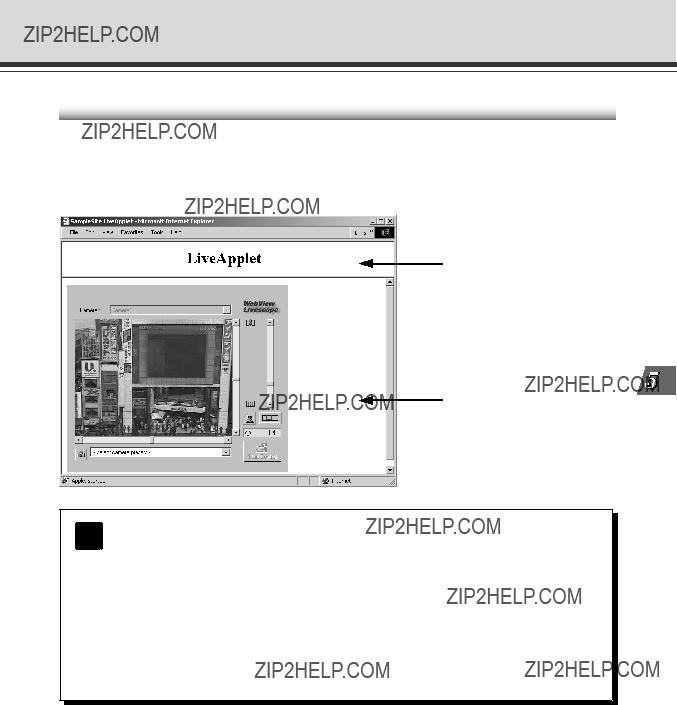

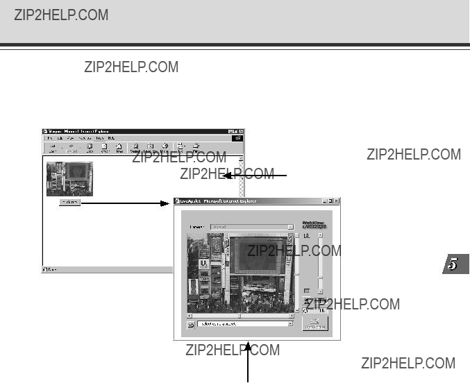


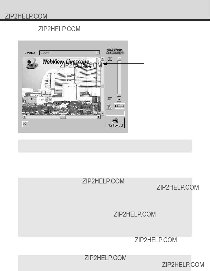


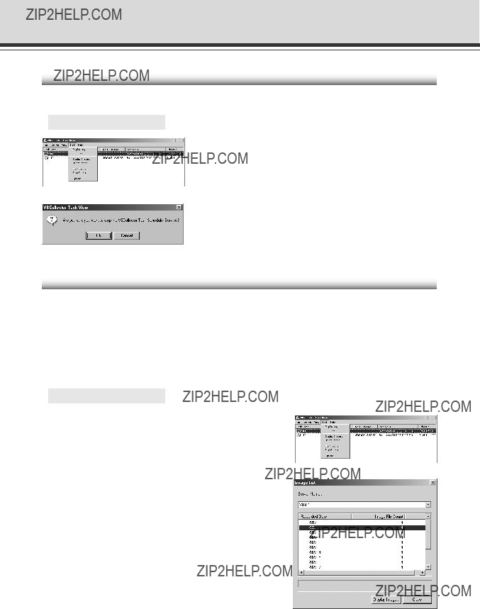
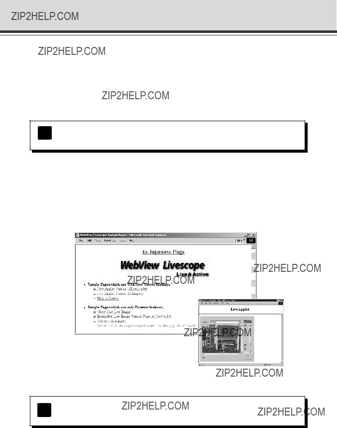
 Helper application launched and displayed


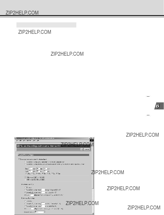

 still picture(s) for every specified interval??? to 3. With these settings, pictures will be recorded
 still picture(s) for every specified interval??? to 8. With these settings, pictures will be recorded and stored every second for 7 seconds starting from the instant the door opens.