TFT LCD Widescreen Television
Instruction Manual
TFTV1524/1923/2224
Please read this manual carefully before connection and use
TFT LCD Widescreen Television
Instruction Manual
TFTV1524/1923/2224
Please read this manual carefully before connection and use

Precautions
TO REDUCE THE RISK OF FIRE OR ELECTRIC SHOCK, DO NOT EXPOSE THIS
APPLIANCE TO RAIN OR MOISTURE.
The lightning flash with arrowhead symbol, within an equilateral triangle, is intended to alert the user to the presence of uninsulated ???dangerous voltage??? within the product???s enclosure that may be of sufficient magnitude to constitute a risk of electric to persons.
The exclamation point within an equilateral triangle is intended to alert the user to the presence of important operating and maintenance (servicing) instructions in the literature accompanying the appliance.
For Customer Use:
Enter below the serial number that is located on the rear of the unit. Retain this information for future ref- erence.
Model No.
Serial No.
Caution:
These servicing instructions are for use by qualified service personnel only. To reduce the risk of electric shock, do not perform any servicing other than that contained in the operating instructions unless you are qualified to do so. Refer to manual for servicing instructions.
Power Supply:
Connect one end of the supplied power cord to the power jack on the unit rear panel and the other end to the
Power Management:
?????? Before plugging the power cord into the AC outlet, make sure that all the connections have been properly made.
?????? If the unit will not be used for a long period of time, disconnect the power and remove the batteries from the remote.

Precautions
FCC Statement:
This device complies with Part 15 of the FCC Rules. Operation is subject to the following two conditions:
?????? This device may not cause harmful interference, and
?????? This device must accept any interference received, including interference that may cause undesired operation.
Note:
This equipment has been tested and found to comply with the limits for Class B digital devices, pursuant to Part 15 of the FCC rules. These limits are designed to provide reasonable protection against harmful interference in a residential installation. This equipment generates, uses and can radiate radio frequency energy and, if not installed and used in accordance with the instructions, may cause harmful interference to radio communications. However, there is no guarantee that interference will not occur in a particular installation. If this equipment does cause harmful interference to radio or television reception, which can be determined by turning the equipment off and on, the user is encouraged to try to correct the interference by one or more of the following measures:
?????? Reorient or relocate the receiving antenna.
?????? Increase the separation between the equipment and receiver.
?????? Connect the equipment into an outlet on a circuit different from that to which the receiver is connected.
?????? Consult the dealer or an experienced radio/TV technician for help
Use of shielded cable is required to comply with Class B limits in Subpart B of Part 15 of the FCC rules. Do not make any changes or modifications to the equipment unless otherwise specified in the manual. If such changes or modifications should be made, you could be required to stop operation of the equipment.
LCD Information
The LCD panel used in this television contains millions of thin film transistors that have been manufactured using a
Copyright Protection
Unauthorized copying, broadcasting, public performance, and lending of disks are prohibited. This product incorporates copyright protection technology that is protected by method claims of certain U.S. patents and other intellectual property rights owned by Macrovision Corporation and other rights owners. Use of this copyright protection technology must be authorized by Macrovision Corporation, and is intended for home and other limited viewing uses only unless otherwise authorized by Macrovision Corporation. Reverse engineering or disassembly is prohibited.
Important Safety Instructions
111 Read Instructions: All the safety and operating instructions should be read before the product is operated.
222 Retain Instructions: The safety and operating instructions should be retained for future reference.
333 Heed Warnings: All warnings on the product and in the operating instructions should be adhered to.
444 Follow Instructions: All operating and usage instructions should be followed.
555 Cleaning: Unplug this product from the wall outlet before cleaning. Do not use liquid cleaners or aerosol cleaners. Use a damp cloth for cleaning.
666 Attachments: Use only attachments recommended by the manufacturer. Use of other attachments may be hazardous.
777 Water and Moisture: Do not use this product near water (e.g., near a bath tub, washbowl, kitchen sink, laundry tub, in wet basements, or near a swimming pool and the like).
888 Accessories: Do not place this product on an unstable cart, stand, tripod, bracket, or table. Use only with carts, stands, tripods, brackets, or tables recommended by the manufacturer
or sold with the product. Any mounting of the product should follow the manufacturer???s instructions and should use a mounting accessory recommended by the manufacturer.
999 A product and cart combination should be moved with care. Quick stops, excessive force, and uneven surfaces may cause the product and cart combination to overturn.
1111 Ventilation: Slots and openings in the cabinet are provided for ventilation to ensure reliable operation of the product and to protect it from overheating. These openings should never be blocked by placing the
product on a bed, sofa, rug, or other similar surface. This product should  not be placed in a
ventilation is provided or the manufacturer instructions have been adhered to.
1111 Power Sources: This product should be operated only from the type of power source indicated on the rating label. If you are not sure of the type of power supply to your home, consult your product dealer or local power company. For products intended to operate from battery power or other sources, refer to the operating instructions.
1111 Grounding or Polarization: This product may be equipped with a polarized
1111
1111 Protective Attachment Plug: The product may be equipped with an attachment plug with overload protection. This is a safety feature. See the operating instructions for replacement or directions to reset the protective device. If replacement of the plug is required, be sure the service technician has used a replacement plug that has the same overload protection as the original plug as speci???ied by the manufacturer.
1111 Lightning: For added protection for this product, unplug it from the wall outlet and disconnect the antenna or cable system during a lightning storm or when it is left unattended and unused for long periods of time. This will prevent damage to the product due to lightning or
1111 Power Lines: An outside antenna system should not be located in the vicinity of overhead power lines or other electric light or power circuits, or where it can fall into such power lines or circuits. When installing an outside antenna system, extreme care should be taken to keep from touching such power lines or circuits, as contact with them might be fatal.
1111 Overloading: Do not overload wall outlets, extension cords, or integral convenience receptacles as this can result in a risk of ???ire or electric shock.
1111 Object and Liquid Entry: Never push objects of any kind into this product through openings as they may touch dangerous voltage points or
1111 Servicing: Do not attempt to service this product yourself as opening or removing covers may expose you to dangerous voltage or other hazards. Refer all servicing to quali???ied service personnel.

Important Safety Instructions
2222 Damage Requiring Service: Unplug this product from the wall outlet and refer servicing to quali???ied service personnel under the following conditions: a) when the
2222 Replacement Parts: When replacement parts are required, be sure that your service technician has used replacement parts speci???ied by the manufacturer or have the same characteristics as the original part. Unauthorized substitutions may result in ???ire, electric shock, or other hazards.
2222 Safety Check: Upon completion of any service or repairs to this product, ask the service technician to perform safety checks to ensure that the product is in proper operating condition.
2222 Wall or Ceiling Mounting: The product should be mounted to a wall or ceiling only as recommended by the manufacturer.
2222 Heat: The product should be situated away from heat sources such as radiators, heat registers, stoves, or other products (including ampli???iers) that produce heat.
2222 Outdoor Antenna Grounding: If an outside antenna is connected to the product, be sure the antenna system is grounded so as to provide some protection against voltage surges and

Table of Contents

Main Features
This product incorporates the LCD display and the TV receiver in one system.
Multiple Mode
TV
AV
COMPONENT
HDMI
VGA
High Quality Property
High Resolution
Adopt an MPEG2 decoding format to achieve horizontal resolution more than 500 lines.
Superior sound
Screen
Support the picture size of a normal screen (4:3) and a wide screen (16:9)
LCD (Liquid Crystal Display)
Designed with color TFT liquid crystal display clearly shows the data.
NOTE: It is normal for a TFT screen to experience some light or dark spots appearing on the LCD screen.
1
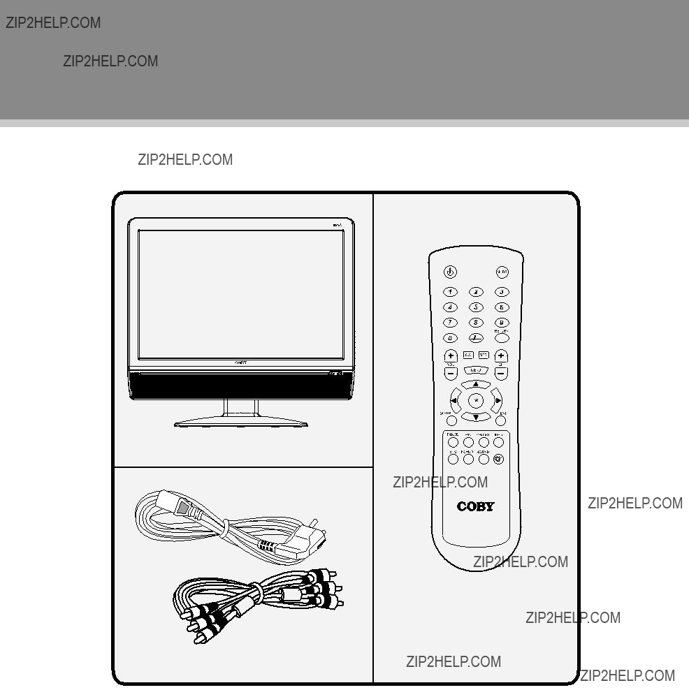
Package Contents
Please make sure the following items are included with your LCD TV/monitor. If any items are missing, contact your dealer.
a, Main Unit
b, Power Cord & RCA Cable c, Remote Control Unit
2

Unit View
4 

1 5 

6 
 7
7 

VESA Standard mounting thread
x 4
4


Wall Mounting
?????? Pinch the edge of the plastic part and remove it from its fixture. Release the screws inside, take off the unit stand.
?????? Use the VESA standard mountings to fix the unit on the wall. Take care when mounting, it may cause damage or serious injury should it fall from its mountings. See the Specification page for VESA informaiton.
3
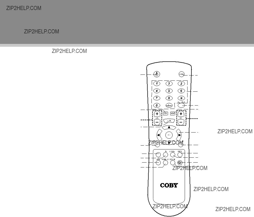
Remote Control
Remote Control Drawing
1.POWER
Press to turn the power on/off.
2.CC
Set the CC mode. (CC on Mute/Off/On).
3.VOLUME +/-
Press to adjust the volume.
4.MENU
Press to show the setup menu.
5.SLEEP
Press to set the sleep timer.
6.P.MODE
Setup the picture mode (Personal, Standard, Soft, Dynamic).
7.FAV
Press to show the Favorite Channel List. If no channel is set on the list, this button does not function.
8.EPG
Press to show the Electronic Program Guide.
9.FORMAT
Press to change the display format as 4:3, Cinema, Normal, 16:9.
10.MODE
Press to select the working mode. (TV, AV,
11.Numeric key pad Press to input data.
12.RETURN
Press to locate the previously viewed channel.
13.MTS
Press to select the TV audio mode.
14.CHANNEL +/-
Press to skip channels.
15.Direction & OK
Press the direction buttons to select the option in the setup menu, press OK to confirm settings.
16.EXIT
Press to exit the menu setup.
17.INFO
Press to show the current working status.
18.
Press to show the channel list.
19.MUTE
Press to muffle/release sound.
20.SOUND
Press to change the sound mode.
4
Remote Control
Remote Control
Preparation
?????? Remove the battery compartment cover located on the rear of the remote control. Insert 2 x ???AAA??? batteries, making sure to match their polarities
?????? Batteries in the remote will last for approximately 6 months under the normal use. Replace the batteries if the remote control does not work. Do not mix old with new batteries, or different types of batteries.
?????? Remove the batteries from the remote if it will not be used for a long period of time.
Warnings:
The battery used in this device may present a fire or chemical burn if mistreated. Do not recharge, disassemble, incinerate, or heat the battery (~212??F).
Keep batteries away from children.
Using the Remote Control
To use the remote, point it at the remote sensor of the player. Operate the remote within 20 feet of the sensor and at an angle of ??30 degrees.
7 

 s
s


MODE
RETURN
The operating distance may vary depending on the brightness around.
Notes:
111 Do not point bright lights directly at the remote control sensor.
222 Do not place objects between the remote control unit and the remote control sensor.
333 Do not use this remote control unit while simultaneously operating the remote control unit of any other equipment.
5
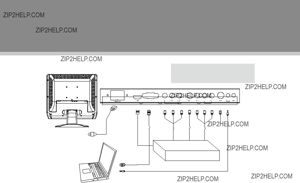
Cable Connections
Figure. Cable connections
Set the unit into the relative input mode to enable the signal pass.
Antenna/Power Connection
111 Connect TV RF sources to the antenna port. TV RF signals include: receiving antenna/CATV net. You can use 75 Ohm coaxial cable to connect outdoor antenna.
222 Insert one end of the supplied power cord to the player???s power jack and the other end to the
Compoent Input (Y Cb/Pb Cr/Pr)
The component port is capable of accepting
111 Connect the Y/Pb/Pr port by the component cable to input the video signal.
222 Connect ???R??? "L" port by the supply AV cable to input the audio signal. The red/white plug of the AV cable is for the audio conneciton and the yellow plug for the video connection.
The
111 Connect the
222 Connect the
AV Input
The CVBS port is capable of accepting signals from standard video sources(e.g., cable/satellite boxes, DVD players, VCRs, etc.)
111 Connect the VIDEO port with the yellow plug of the the supplied AV cable.
222 Connect the L/R port with the red & white plug of the supplied AV cable to input the audio signal.
VGA Input
The VGA port of the TV is capable of accepting
HDMI Input
HDMI (High De???inition Multimedia Interface) is a new type of connection that transmits digital audio and video signals simultaneously over a single cable. A HDMI cable is required for the HDMI connection.
These HDMI input connectors are capable of receiving video at resolutions up to 1080p
6
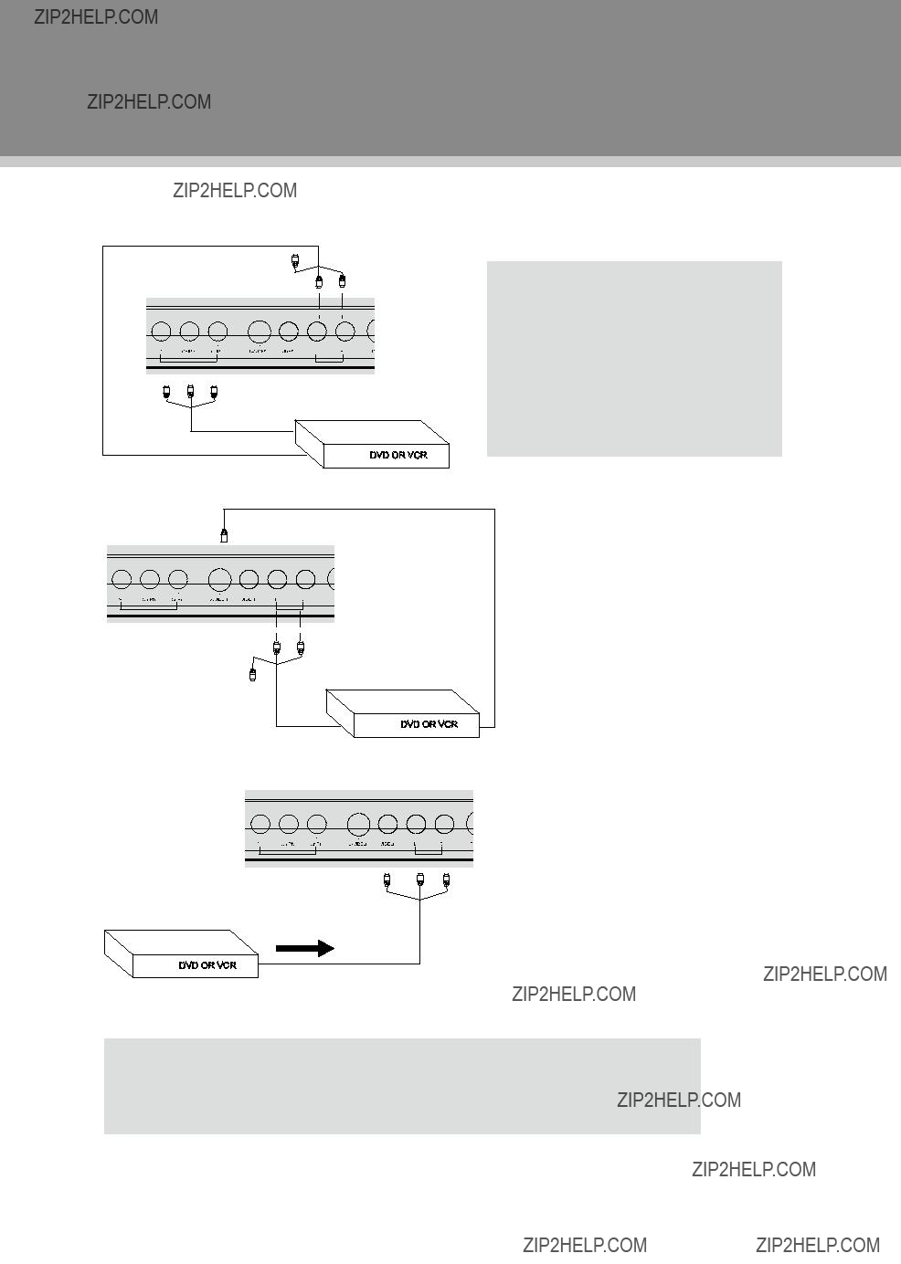
Cable Connections
Figure. Cable connections
Component Input
NOTE:
We supply the AV cable and the power cord with this product.
The white/red plug of the AV cable is for the audio connection and the yellow plug for the video connection.
The white/red plug of the AV cable can also be used separately to input the audio signal in the
AV Input
NOTE:
111 Be sure to have all necessary connections properly done before connect the power supply.
222 When input the AV signal, refer to the manual of the external sources as well.
7
TV Function
TV Function
Preparations
111 Connect the cables.(Refer to the ???Cable Connections??? section for details). 222 Press the POWER button to turn on the player.
333 Press the MODE button to select the TV signal mode.
444 Press the CH+/- buttons to skip channels. Or you can press the number buttons to input channels directly. For initial use, you need to scan channels under the Channel Menu. See the "Channel Menu" section for details.
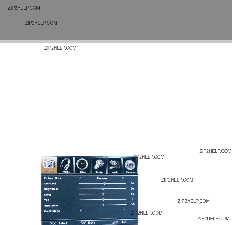
TV Setup Menu
Various features can be preset through the TV setup menu.
?????? Press MENU to display the setup menu, TV setup menu consists of PICTURE, AUDIO, TIME, SETUP, LOCK as well as CHANNEL.
?????? Press the left/right direction button to select the desired submenu, press OK to enter.
While working with the menu,
111 Press the up/down direction button to select the option. 222 Press the left/right direction button to adjust.
333 Press MENU to exit/back up menu.
Warm
Picture Menu
8

TV Function
Audio Menu
9

TV Function
Setup Menu
10

AV Function
Channel Menu
11
AV Function
AV Function
The player???s AV input function enables the user to view programs from external input sources. 111 Connect the external AV signal source. Refer to the ???Cable Connection??? section for details 222 Press the MODE button to select the relevant AV mode (AV,
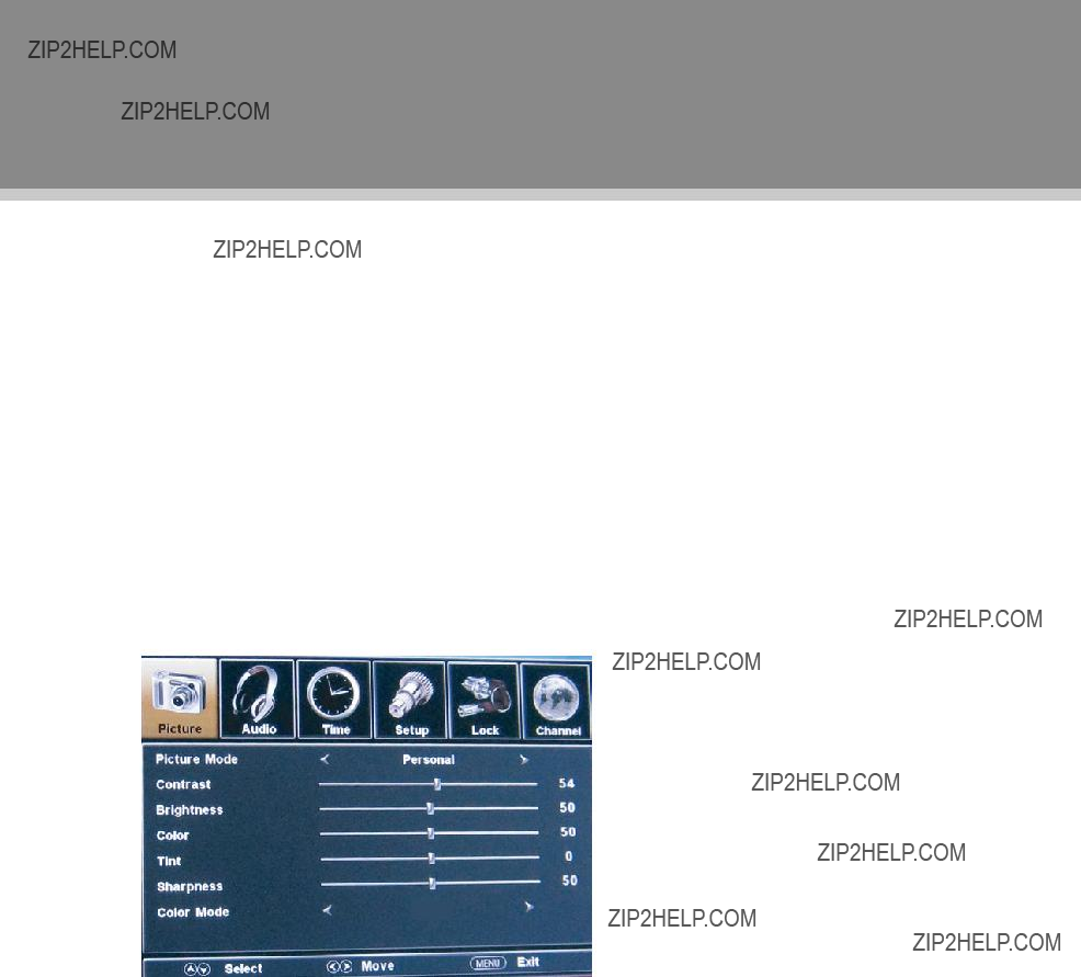
AV Setup Menu
Various features can be preset through the AV menu.
?????? Press the MENU button to display the AV menu. AV setup menu consists of PICTURE, AUDIO, TIME, SETUP as well as LOCK.
?????? Press the left/right direction button to select the desired
While working with the menu
111 Press the up/down direction buttons to select the desired item. 222 Press the left/right direction button to adjust.
333 Press MENU to exit/back up the menu.
Warm
NOTE: Please see the TV section for menu descriptions
12
PC Function
PC Function
You can use the unit???s TFT LCD as your computer???s monitor.
111 Shut down both units and connect the VGA jack and PC Audio In jack. See the ???Cable Connection??? section.
222 Turn on the units and press the MODE button to select VGA
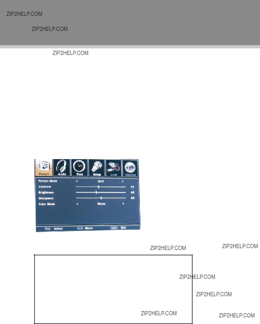
PC Setup Menu
Various features can be preset through the PC menu.
?????? Press the MENU button to display the PC menu. PC setup menu consists of PICTURE, AUDIO, TIME as well as SETUP.
?????? Press the left/right direction button to select the desired
While working with the menu
111 Press the up/down direction buttons to select the desired item. 222 Press the left/right direction button to adjust.
333 Press MENU to exit/back up the menu.
NOTE: Please see the TV section for menu descriptions
Adjust the PC Screen
Upon switching to the PC mode, the moniter will be automatically regulated for a proper functioning. If the result is not up to your expectation, please perform the following steps to adjust the screen manually .
111 Enter the ???Advanced???
222 Or if you still have problem with the monitor after, adjust
13

Trouble Shooting
If you have a problem with this device, please read the troubleshooting guide section and check our website at www.cobyusa.com for Frequently Asked Questions (FAQs) and firmware updates. If these resources do not resolve the problem, please contact Technical Support.
Address
COBY Electronics Technical Support
Maspeth, NY 11378
techsupport@cobyusa.com
Web
www.cobyusa.com
Phone
Saturdays 9:00AM
14
Specification
TFTV 1524
15

Specification
TFTV 2224
P/N:
Speci???ications and manual are subject to change without prior notice.
16