2010 Buick Enclave Owner Manual M
In Brief . . . . . . . . . . . . . . . . . . . . . . . .
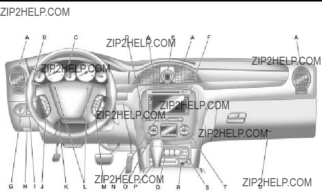
Instrument Panel . . . . . . . . . . . . . .
Initial Drive Information . . . . . . . .
Vehicle Features . . . . . . . . . . . . .
Performance and
Maintenance . . . . . . . . . . . . . . . .
Keys, Doors and Windows . . .
Keys and Locks . . . . . . . . . . . . . . .
Doors . . . . . . . . . . . . . . . . . . . . . . . . . .
Vehicle Security. . . . . . . . . . . . . .
Exterior Mirrors . . . . . . . . . . . . . . .
Interior Mirrors . . . . . . . . . . . . . . . .
Windows . . . . . . . . . . . . . . . . . . . . .
Roof . . . . . . . . . . . . . . . . . . . . . . . . . .
Seats and Restraints . . . . . . . . .
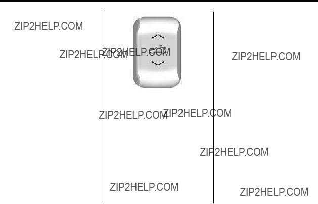
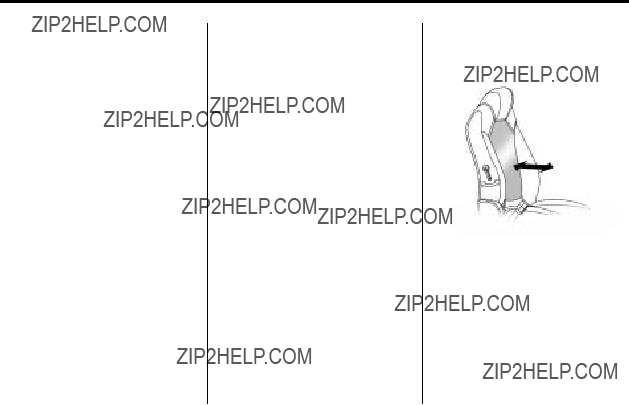
Head Restraints . . . . . . . . . . . . . . .
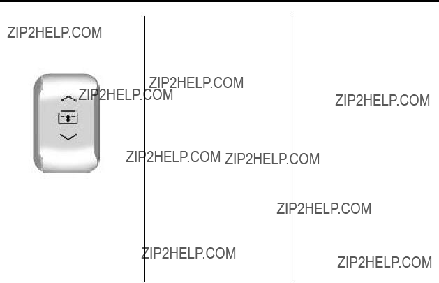
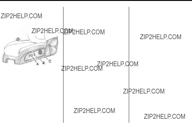
Front Seats . . . . . . . . . . . . . . . . . . . .
Rear Seats . . . . . . . . . . . . . . . . . . . .
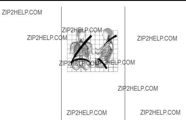
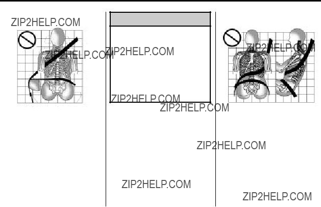
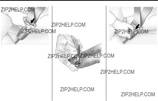
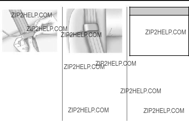
Safety Belts . . . . . . . . . . . . . . . . . .
Airbag System . . . . . . . . . . . . . . . .
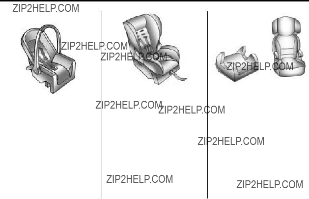
Child Restraints . . . . . . . . . . . . . .
Storage . . . . . . . . . . . . . . . . . . . . . . .
Storage Compartments . . . . . . . .
Additional Storage Features . . .
Roof Rack System . . . . . . . . . . . . .
Instruments and Controls . . . .
Controls . . . . . . . . . . . . . . . . . . . . . . .
Warning Lights, Gages, and
Indicators . . . . . . . . . . . . . . . . . . .
Information Displays . . . . . . . . . .
Vehicle Messages . . . . . . . . . . . .
Vehicle Personalization . . . . . . .
Universal Remote System . . . .
Lighting . . . . . . . . . . . . . . . . . . . . . . .
Exterior Lighting . . . . . . . . . . . . . . .
Interior Lighting . . . . . . . . . . . . . . . .
Lighting Features . . . . . . . . . . . . . .
Infotainment System . . . . . . . . .
Introduction . . . . . . . . . . . . . . . . . . . .
Radio . . . . . . . . . . . . . . . . . . . . . . . . . .
Audio Players . . . . . . . . . . . . . . . .
Rear Seat Infotainment . . . . . . .
Phone . . . . . . . . . . . . . . . . . . . . . . . .
Climate Controls . . . . . . . . . . . . .
Climate Control Systems . . . . . .
Air Vents . . . . . . . . . . . . . . . . . . . . . . .
Driving and Operating . . . . . . . .
Driving Information . . . . . . . . . . . . .
Starting and Operating . . . . . . .
Engine Exhaust . . . . . . . . . . . . . .
Automatic Transmission . . . . . .
Drive Systems . . . . . . . . . . . . . . . .
Brakes . . . . . . . . . . . . . . . . . . . . . . .
Ride Control Systems . . . . . . . .
Cruise Control . . . . . . . . . . . . . . . .
Object Detection Systems . . . .
Fuel . . . . . . . . . . . . . . . . . . . . . . . . . .
Towing . . . . . . . . . . . . . . . . . . . . . . .
Conversions and
Vehicle Care . . . . . . . . . . . . . . . . .
General Information . . . . . . . . . .
Vehicle Checks . . . . . . . . . . . . . . .
Headlamp Aiming . . . . . . . . . . .
Bulb Replacement . . . . . . . . . .
Electrical System . . . . . . . . . . . .