APPLICATION NOTE
User Manual of
RDS/EON Car Radio System
CCR612 (V0.3)
AN96029
APPLICATION NOTE
User Manual of
RDS/EON Car Radio System
CCR612 (V0.3)
AN96029

Philips Semiconductors
Abstract
The CCR612 is a computer controlled car radio system based on a P83CE528 micro controller. It controls a
The system contains functions such as PLL tuning, IF control, stereo decoding, RDS/RBDS+EON decoding, IAC, sound switching, sound fader control, LCD display, cassette interface, external audio input jack and a detachable front. An interface to control a
Radio control and RDS/RBDS+EON processing are combined in a single microcontroller.
"The purchase of Philips' complete set of Integrated Circuits as specified in this User Manual for manufacture of a radio system conforming the relevant specification as herein given, secures immunity from suit on unauthorized use of those Philips' patent rights, which specifically relate to automatic broadcast station storage (AST) and/or radio data system (RDS) features."
Purchase of Philips I2C components conveys a license under the I2C patent to use the com- ponents in the I2C system, provided the system conforms to the I2C specifications defined by Philips.
?? Philips Electronics N.V. 1997
All rights are reserved. Reproduction in whole or in part is prohibited without the prior written consent of the copy- right owner.
The information presented in this document does not form part of any quotation or contract, is believed to be accurate and reliable and may be changed without notice. No liability will be accepted by the publisher for any consequence of its use. Publication thereof does not convey nor imply any license under patent- or other industrial or intellectual property rights.
2

Philips Semiconductors
APPLICATION NOTE
User Manual of
RDS/EON Car Radio System
CCR612 (V0.3)
AN96029
Author(s):
A.Demmers M. Verheijden
Product Concept & Application Laboratory Eindhoven,
The Netherlands
Keywords
Car Radio
RDS
RBDS
EON
CCR612
ICE (TEA6811 / TEA6822)
SOFAC (TEA6320, 6321, 6322 or 6323)
Number of pages: 94
Date:
3

Philips Semiconductors
Summary
CCR612 is a computer controlled car radio system based on a P83CE528 microcontroller. It controls a
The system contains functions such as PLL tuning, IF control, stereo decoding, RDS/RBDS+EON decoding, IAC, sound switching, sound fader control, LCD display, cassette interface, external audio input jack and a detachable front. An interface to control a
Radio control and RDS/RBDS+EON processing are combined in a single microcontroller.
4

Philips Semiconductors
CONTENTS
1 INTRODUCTION . . . . . . . . . . . . . . . . . . . . . . . . . . . . . . . . . . . . . . . . . . . . . . . . . . . . . . . . . . . . . . . 11
1.1 Definitions, Acronyms and Abbreviations . . . . . . . . . . . . . . . . . . . . . . . . . . . . . . . . . . . . . . 12
1.2 References . . . . . . . . . . . . . . . . . . . . . . . . . . . . . . . . . . . . . . . . . . . . . . . . . . . . . . . . . . . . . . 12
2.1.7.2Front Panel Part
2.1.8 Diagram ICE module. . . . . . . . . . . . . . . . . . . . . . . . . . . . . . . . . . . . . . . . . . . . . . . 17 2.1.9 Diagram PACS Sub Board . . . . . . . . . . . . . . . . . . . . . . . . . . . . . . . . . . . . . . . . . 18
2.1.10PCB
4 CCR612S PINNING AND INTERFACING . . . . . . . . . . . . . . . . . . . . . . . . . . . . . . . . . . . . . . . . . . . 30 4.1 Pinning overview . . . . . . . . . . . . . . . . . . . . . . . . . . . . . . . . . . . . . . . . . . . . . . . . . . . . . . . . . . 30 4.2 Factory options . . . . . . . . . . . . . . . . . . . . . . . . . . . . . . . . . . . . . . . . . . . . . . . . . . . . . . . . . . . 38 4.2.1 Diode options . . . . . . . . . . . . . . . . . . . . . . . . . . . . . . . . . . . . . . . . . . . . . . . . . . . . 38
4.2.2 Automatically detected options . . . . . . . . . . . . . . . . . . . . . . . . . . . . . . . . . . . . . . 39 4.3 I2C bus addresses . . . . . . . . . . . . . . . . . . . . . . . . . . . . . . . . . . . . . . . . . . . . . . . . . . . . . . . . . 39
4.4 The keyboard . . . . . . . . . . . . . . . . . . . . . . . . . . . . . . . . . . . . . . . . . . . . . . . . . . . . . . . . . . . . 39 4.4.1 Fixed keyboard . . . . . . . . . . . . . . . . . . . . . . . . . . . . . . . . . . . . . . . . . . . . . . . . . . . 40 4.4.2 Detachable keyboard . . . . . . . . . . . . . . . . . . . . . . . . . . . . . . . . . . . . . . . . . . . . . . 40 4.4.3 Keyboard options . . . . . . . . . . . . . . . . . . . . . . . . . . . . . . . . . . . . . . . . . . . . . . . . . 41
4.5Power stabilizer interface. . . . . . . . . . . . . . . . . . . . . . . . . . . . . . . . . . . . . . . . . . . . . . . . . . . 42
4.6LCD display. . . . . . . . . . . . . . . . . . . . . . . . . . . . . . . . . . . . . . . . . . . . . . . . . . . . . . . . . . . . . . 44
4.7 Non Volatile Memory. . . . . . . . . . . . . . . . . . . . . . . . . . . . . . . . . . . . . . . . . . . . . . . . . . . . . . . 45
6 FUNCTIONAL DESCRIPTION . . . . . . . . . . . . . . . . . . . . . . . . . . . . . . . . . . . . . . . . . . . . . . . . . . . . 57 6.1 Switching on / off . . . . . . . . . . . . . . . . . . . . . . . . . . . . . . . . . . . . . . . . . . . . . . . . . . . . . . . . . . 57 6.2 Tuning . . . . . . . . . . . . . . . . . . . . . . . . . . . . . . . . . . . . . . . . . . . . . . . . . . . . . . . . . . . . . . . . . . 58 6.2.1 Band switching . . . . . . . . . . . . . . . . . . . . . . . . . . . . . . . . . . . . . . . . . . . . . . . . . . . 58 6.2.2 Manual/search tuning . . . . . . . . . . . . . . . . . . . . . . . . . . . . . . . . . . . . . . . . . . . . . 58 6.2.3 Frequency scan . . . . . . . . . . . . . . . . . . . . . . . . . . . . . . . . . . . . . . . . . . . . . . . . . . 60
5

Philips Semiconductors
6

Philips Semiconductors
Change history of: User Manual of
Modifications with respect to the application note " User Manual of
1.Added use of more types of Sofac(TEA6320, TEA6321, TEA6322, TEA6323), adapted sound setting
2.Band selection diode 2 moved to other pin
3.Sleeptimer changed from 30 minutes to 1 hour
Modifications with respect to the application note " User Manual of
1.TEA6821 replaced by TEA6822.
2.Frequency counter resolution for FM changed from 5 kHz to 6.25 kHz.
3.Volume level during traffic announcements made adjustable by the user in the option programming menu.
4.PTY search algorithm changed.
5.Functionality of PTY icon changed.
6.Manual tuning algorithm changed.
7.For MW band only tuning on grid is possible.
8.Manual tuning grid for USA option changed from 50 kHz to 100 kHz.
9.Search tuning grid for USA option changed from 100 kHz to 200 kHz.
10.Pin 9 of the microcontroller (SECUR) not used any more (security functionality stays the same).
11.Input added for "Phone mute".
12.Checking on not initialized EEPROM and preprogramming them with default values (listed in appendix II) at radio switch on.
13.Polarity of pin EXSTAT changed.
14.Crystal frequency of microcontroller changed from 8.664 MHz to 12 MHz.
15.PTY code not longer stored in EEPROM.
16.When RDS regional mode is on, the radio is now also allowed to switch over to stations with the same
17.Display message during AST search changed from "AST SCAN" to "STORE".
7

Philips Semiconductors
Change history of: Diagrams and performance of R(B)DS Car Radio CCR612 with Cassette Deck.
DIFFERENCES WITH PREVIOUS CCR612 (AN95070).
Mainboard part 1:
Two diodes were added to improve reset behaviour
In case a static on/off key is used, C144/C154/C151 must be 10??F i.s.o. 100nF.
Mainboard part 2:
Option diode D8 is removed. Option diode D2 is now connected to pin 21.
Option diode D4 and D6 are removed.
DIFFERENCES WITH PREVIOUS CCR612 (AN94067).
This note, Diagrams and Performance, valid for CCR612 radio sample (version D) controlled by CCR610S or CCR612S software (the latter, also for
Modifications and Improvements.
General:
Component numbering CCR612 radio sample. Unlike previous note, the electricalcomponent numbers of the PCB boards (Fig. 13b and Fig. 13d) do match with the electrical diagrams (Fig.4, Fig.7 and Fig.9), which belong to the CCR612 radio sample (Version D).
Main Board part 1a, 1b and 1c (pages 14, 15 and 16).
-A
-Switched battery voltage circuit improved. Which delivers for external use a battery voltage only when the radio is in the Power On mode for; supplying the illumination of the detachable front and delivering a switched plus voltage for the
-A telephone mute circuit between Connector Block and Micro Controller pins (AUMUTE and OPTROW) has been introduced. For this feature the former security contact is used. In general this is not a problem because the trend to use a security contact is decreasing by the use of detachable fronts.
-For part 1c only, the bleep input is moved from the source selector (HEF4052B) input to the Audio Pre Amplifier (TDA6320T) input.
Main Board part 2a and 2b (Page 17 and Page 18 ).
8

Philips Semiconductors
-Telephone mute circuit, between optrow (40) and Aumute (43) introduced.
-The use of one crystal (8.66 MHz) for both micro and RDS demodulator is not possible in this set. Because for improved RDS behaviour more 'speed' is needed which requires a crystal of 12 MHz for the micro and 8.66 MHz or 4.33 MHz for the RDS demodulator.
-For part 2b only, in the lines ON/OFF, DATA and SCL between detachable front and micro ESD protection circuits are introduced which consists of a few resistors, zener diode 5V6 (BZX79C) and 2 diodes (BAV99).
Key and Display panel SB1b (Page 21).
-Following a now a days trend the power switch, in the ON/OFF radio line,is moved to the detachable front. That means two extra contacts on both detachable front and radio are needed.
Diagram ICE Module (page 22).
-The diagram of the ICE module (Euro 1, standard) is modified, the "second" IC TEA6821 is replaced by the successor TEA6822.
-The diagram of the ICE module (Euro 1, standard) is modified, the "second" IC TEA6821 is replaced by the successor TEA6822.
Improvements of the TEA6822 with respect to the 6821: At AM.
-Sensitivity higher. Distortion and AM and AF output less fieldstrength dependent
At FM.
-Interference Absorbtion improved by double detection.
-Gain less temperature dependent
-AM to FM switching in less then 0.5 seconds
With respect to software control.
-Level ADC extended from 3 to 4 bits.
-Multipath sensitivity to be set.
-Level temperature coefficient to be chosen (1 bit) for CDSP applications.
-Counter
9

Philips Semiconductors
10
Philips Semiconductors
1 INTRODUCTION
CCR612 is a computer controlled
Digital PLL tuning for FM, MW, LW and SW (49m) bands, (factory options: MW, LW and SW disable). Factory option for application in different parts of the world (e.g. USA / Europe) concerning the band limits and tuning grid.
Manual Tuning, Search Tuning and Local/Dx handling.
Frequency Scan (Continuous Search, pausing 6 seconds on every station). Automatic Store Tuning (AST).
Search for Traffic Programmes (TP) or specific Program Types (PTY).
Presets: 6 in each of the bands: FM1, FM2,
Sound control: volume, bass, treble, balance, fader, loudness and mute via
LCD display (I2C bus controlled) displaying:
-system status (band / frequency / preset number / modes).
-RDS Programme Service name (PS).
-RDS Programme Type (PTY).
-Sound control settings (Bass, Treble, Balance, Fader).
Power stabilizer control with diagnostic functions.
User control up to 27 keys with either a fixed keyboard, a keyboard on a detachable front or a combination of both.
User programmable options.
Cassette Interface including MTL, Dolby, AMS (Automatic Music Search) and Solenoid control. Input jack for external audio source.
Input for phone mute detection.
An interface for the SCC600
11

Philips Semiconductors
1.1De??nitions, Acronyms and Abbreviations
NOTE: RBDS is an extension of the European RDS system. Every reference in this document to RDS is also valid for the RBDS system unless, otherwise specified.
1.2References
[1]Outline specification of
[2]Specification of the radio data system RDS for VHF/FM sound broadcasting,
[3]United States RBDS standard January 8, 1993
12

Philips Semiconductors
2 HARDWARE CONFIGURATION
2.1Block diagram CCR612
Figure 1 shows the block diagram of the
-Power amplifier ( 2 speaker / 4 speaker / output power)
-Sound control (Potentiometer control / I2C control)
This hardware description only describes the use of the sofac TEA6320.
2.1.1Main Board Part 1a (Basic AM/FM stereo Radio Part)
Page 81 shows the circuit diagram of the basic radio part, which consist of the following parts: ICE receiver module, audio
AM/FM - ICE module (TEA6811V,TEA6822T)
The AM/FM - ICE module is a
AM receiver FM receiver
-FM stereo decoder
-Interference Absorption Circuit (or Noise Blanker)
-Station detector and weak signal control
PLL tuning Synthesizer
The complete circuit diagram of the ICE Module (version euro 1) is shown on page 89. For a detailed description of functions and performance see Ref.4.
Audio Pre Amplifier (TEA6320)
Power Amplifier (TDA8561Q)
Car radio power amplifier with dynamic distortion detector and diagnostics in a 17 lead single in line (SIL) plastic power package. It contains 4 x 12W (2 ohm) and 4 x 7W (4 ohm)
Supply voltage Stabilizer (TDA3602)
Three output voltage regulator, in SIL 9 package, for use in car radios with a microprocessor. It contains two computer controlled voltage regulators with foldback current protection (Regulators 1 and 2) and one fixed voltage regulator (3) that also operates during load dump and thermal shutdown. This regulator is used to supply the microprocessor.
13

Philips Semiconductors
FM / AM
Figure 1 Block diagram CCR612
14

Philips Semiconductors
Isolator ( Differential Line Receiver, TDA8579T)
Dual
PACS - Sub Board (TEA6850)
PACS controls the I.F. Selectivity / Bandwidth to avoid receiving problems due to near adjacent channels (especially for Europe, spacing of 100 kHz is not an exception). In order to show the improvements of the selectivity and dynamic behaviour of the radio by the use of PACS an ON/OFF switch has been used on the front panel.
A complete circuit diagram of the PACS board is shown on page 94 and for description of the functions, alignment and performance see Ref.5.
2.1.2Main Board Part 1b (Optional Power Ampli??er, 2 x TDA8561Q)
Page 82 shows the previous circuit diagram (paragraph 2.1.1 Basic AM/FM stereo Radio Part) equipped with circuits for 4 x 24W (4 ohm) audio output power.
Power Amplifier (2 x TDA8561Q)
Single circuit configuration 2 x 24W (4 ohm) bridge amplifiers, package SIL 17 pins Quil.
2.1.3Main Board Part 1c (Optional Source Sel. & Audio Contr.
HEF4052B/TDA1526)
Page 83 shows the circuit diagram from paragraph 2.1.1 (Basic AM/FM stereo Radio Part) equipped with the DC controlled audio
Audio
An active stereo,tone/volume control for car radios. It includes functions for bass and treble, control, volume control with built in contour (can be switched off) and balance.All these functions can be controlled direct by DC voltages or via single linear potentiometers.
Source selector circuit (HEF4052B).
The HEF4052B is a dual 4 channel analogue multiplexer/demultiplexer with common channel select logic. In this case used for four stereo inputs: radio, cassette and external input.
15

Philips Semiconductors
2.1.4Main Board Part 2a (
Page 84 shows the circuit diagram of the RDS Demodulator, Micro controller (which combines all radio control functions as well as RDS decoding) and EEPROM.
Microcontroller (P83CE528EFB)
Main microcontroller (CCR612S), a derivative of the 8051
EEPROM
The PCF8594E is a 512 byte, 5V Electrically Erasable Programmable Read Only Memory (EEPROM) that can be 100,000 times
RDS Demodulator (SAA6579T)
RDS Demodulator IC, which includes the 57 kHz
2.1.5Main Board Part 2b (Detachable Front)
Page 85 shows the previous circuit diagram (paragraph 2.1.4) of the micro controller board extended with the possibility to use a detachable front panel.
2.1.6Main Board Part 3 (Cassette Interface including Dolby B*)
Page 86 shows the circuit diagram of the cassette interface circuit for the Philips cassette deck
The TEA0675 includes head and equalization amplifiers with electronically switchable time constants. Furthermore the TEA0675 includes electronically switchable inputs for tape drives with reverse heads. This device also detects pauses of music in the AMS (Automatic Music Search) scan mode.
16

Philips Semiconductors
2.1.7Front Panels
2.1.7.1Front Panel Part
Page 87 shows the circuit diagram of the key and display panel.
LCD Driver (PCT8576CT)
The PCF8576 is a peripheral device which interfaces to almost any liquid crystal display (LCD) having low multiplex rates. It generates the drive signals for any static or multiplex LCD containing up to four back planes and up to 40/24 segments and can easily be cascaded for larger LCD applications.
2.1.7.2Front Panel Part
Page 88 shows the circuit diagram of the detachable keyboard front. The circuit includes an I/O expander PCF8574, the keyboard and LCD display unit are placed on the detachable front controlled by a second I2C bus. Eight contacts are required to connect the detachable front to the radio. Furthermore there is a fixed
2.1.8Diagram ICE module.
Standard Version EURO 1
Page 89 shows the complete circuit diagram of the ICE AM/FM tuner module version Euro 1. The Standard Euro 1 module is intended for European frequency ranges.
The module contains the IC's TEA6811V and TEA6822T with the following main functions;
17

Philips Semiconductors
EURO 2, USA 1 and JAPAN 1 ICE MODULE VERSIONS.
By slight circuit modifications of the standard module (EURO 1), matched module versions with better performance for e.g. USA an Japan can be derived. The needed modifications for the different modules are:
2.1.9Diagram PACS Sub Board
Page 94 shows the diagram of the PACS
2.1.10PCB
CCR612/Mainboard PCB
ICE module board PCB
18

Philips Semiconductors
2.2Performance of the radio
19

Philips Semiconductors
FM characteristics
Vsupply = 14.4 V, Tamb = 25 ??C, fo = 98 MHz, fdev = ??22.5 kHz, fmod = 1 kHz unless otherwise specified. Dummy aerial as shown in Figure 2.
Radio aerial input (150 Ohm)
20
Philips Semiconductors
AM characteristics
Vsupply = 14.4 V, Tamb = 25 ??C, fo = 999 kHz, m = 0.3, fmod = 1 kHz unless otherwise specified. Dummy aerial as shown in Figure 3.
21

Philips Semiconductors
22

Philips Semiconductors
PLL tuning principle
Manual tuning up / down
First one step, next after 0.5 seconds. Fast repetition at 12.5 times per second.
Local/Dx switching
The Local/Dx feature controls the search sensitivity. Default after switching on is always Dx. In the TEA6811 a tuner attenuator for the
Search tuning up / down
Sensitivity is controlled by Local/Dx. If after one complete band sweep in Local mode no station is found, the radio switches automatically to Dx. During search tuning the running frequency is displayed and the radio is muted.
Frequency Scan
Continuous automatic search tuning, pausing for 6 seconds on every station.
AST (Automatic Store Tuning) for FM and MW band
AST switches to
Programme preset memory
For each band (FM1, FM2, MW, LW, SW (49m),
Whenever another band is selected, the radio reverts to the last frequency tuned to in the new band (this can be either a preset frequency or a manually tuned frequency).
Programme preset up / down control
Programme presets can be stored and recalled by two key control (up and down) or by 6 separate preset keys.
23

Philips Semiconductors
AF follow mode
When AF follow mode is on, the set will regularly measure the signal strength of alternative frequencies and compare it with the current station. If an alternative frequency offers better quality, the radio will switch over and update the alternative frequency list. The measuring scheme is designed to cause minimum noticeable disturbance for the listener. The interval time between two measurements depends on the signal quality.
Intelligent preset programme recall
If an FM programme preset with a known PI code is recalled, the primary frequency and all alternative frequencies stored in the programme preset memory are examined. The frequency with the best signal quality broadcasting the correct PI code will be selected. Only when the programme is not found on one of the AFs, after 6 seconds a search is started for a station with a proper PI code.
TA mode
In TA mode the radio only searches for transmitters that transmit the RDS traffic programme on the same station or on EON linked stations. The radio will automatically start a search when switching TA mode on and the current station is not a traffic station.
PTY scan mode
In PTY scan mode the radio searches for transmitters that transmit the
Last status memory: band, frequency, PI code, AF follow mode on/off status and TA mode on/off status are stored in memory. This status is recalled during switch on.
RDS
Bit, block and group synchronisation. (inclusive RBDS
Data collection and decoding of:
AF follow mode using PI and AF (see also Tuning).
Display of the programme service name in 8
Display of AF, TP, TA, PTY, EON and Regional mode status via icons.
Regional mode on/off switching. When Regional mode is on, the radio will, during AF switching, only switch over to stations with exactly the same
24

Philips Semiconductors
switch over to stations broadcasting regional variants of the original station. (so called "generic" or "family" PI codes). For USA application (RBDS) the regional function will only work for PI codes above B000hex. PI codes below B000hex do not have regional variants. Af switching is only allowed to stations with exactly the same PI code.
User Control
Up to 27 Local control keys on either a fixed, a detachable keyboard or a combination. Triangular matrix using 7 lines.
Detachable front
Optionally, the keyboard and the LCD display unit can be placed on a detachable front controlled by a 2nd I2C bus. Only 5 contacts are required to connect the detachable front (6 if it hosts also the power key). No extra hardware is required to detect its presence.
EON
If the TA option is on, switch temporarily to an other station if EON information indicates a traffic announcement on another network even when the radio is muted or in
Maintain lists of alternative frequencies of other stations stored in preset memory with information received via EON on the currently tuned station.
Display by means of an icon whether EON data is received and whether an EON traffic announcement is broadcast.
Display
143 Segment LCD with Umlaut (??) characters, 1:4 multiplexed divided into:
8 Alphanumeric characters + decimal point are used to display:
-Band and frequency (Example: "FM 103.50")
-Indication "BALANCE", "FADER", "TREBLE", "BASS" and their value.
-RDS programme service name (PS) in 8 alphanumeric characters.
-RDS programme type (PTY)
-"MUTE", in case the user mutes the radio, cassette or external
-Cassette mode function such as "PLAY >", "CAS WIND", etc.
-
7 Segment display for the current programme preset number.
25

Philips Semiconductors
Non Volatile Memory
512 bytes EEPROM. The following information is stored in NVM:
System status e.g.: band, audio source (radio /
For each band FM1, FM2,
For each FM preset:
-
-PS Name
-AF List (9 AF's)
-AF follow mode on/off.
Audio controls: volume, bass, treble, balance, fader and loudness. Preprogramming EEPROM
At
Appendix II lists the default values written to NVM during initialization.
Sound
Volume, bass, treble, balance and fader control with
Mute function.
Automatic muting during tuning and AST search (silent tuning).
Loudness function.
26

Philips Semiconductors
Sound settings are stored at
"Bleep" tone to confirm user actions such as storing a programme preset, entering AST mode, etc. Mono / stereo function.
Output pins for mute, loudness and traffic announcement, for use with conventional audio control circuitry.
Automatic mute of radio during "Phone mute" detection.
*1 ?? TDA8561Q amplifier for 4 ?? 12 W ( 2?? load) or 4 ?? 7 W or 2 ?? 24 W bridged application. (both at 4?? load)
*1 ?? TDA8562Q amplifier for 4 ?? 12 W ( 2?? load) or 4 ?? 7 W (4?? load)
*2 ?? TDA8561Q amplifier for 4 ?? 24 W bridged application. (4?? load)
Diagnostic control:
*
*signal clipping, via an icon and stepwise decrease of bass and or volume
Optional conventional
Options
Diode programmable
-Detachable front
-Available frequency bands
-Static on/off switch
-Frequency band limits and tuning grid for different parts of the world. This option also selects between RDS (Europe) and RBDS (USA).
User programmable
-2 / 4 Loudspeakers
-Loudness on / off
-TA volume level
Automatically detected
-Digital sound control chip or conventional audio control circuitry
-Loudness
-Presence of the
-Availability of a power amplifier with diagnostics facilities
27

Philips Semiconductors
Power connections
Continuous power supply input. Normally connected directly to the car battery. All supply power is drawn from this supply.
Ignition key input. Normally connected to the accessory contact of the ignition switch. Used only for switching the radio on/off. This input is also used when the static on/off switch option is chosen instead of the momentary on/off key.
Switching on/off
Recall of last system status (e.g.: frequency, band, sound control settings, RDS status and last selected audio source).
Switch on by:
-Power key, can be static or momentary.
-Ignition contact (after the set was switched off by turning the ignition contact off).
Switch off by:
-Power key, can be static or momentary.
-Ignition contact.
-Removal of detachable keyboard.
When switched on while the ignition contact is (and remains) off, the set will automatically switch off after 60 minutes.
The radio will switch on again when switched off due to a power dip during engine start.
Disc up/down keys for selecting the next/previous disc. Track up/down keys for selecting the next/previous track.
Fast forward/reverse keys for jumping some grooves forward/backward.
Shuffle on/off key, for playing the tracks in random order. (The user can make a selection between tracks on the current disc only or tracks on all discs.)
Repeat on/off key, for repetitive play of the current track or the current disc.
28

Philips Semiconductors
Optional source switching to external mode (external plug is in) or always to radio mode (option diode D6 is present) when the tape is ejected.
External audio input:
Automatically switches to external audio source when a connector is inserted.
Optional source switching to cassette mode (tape is in) or always to radio mode (option diode D6 is present) when the external plug is removed.
29

Philips Semiconductors
4 CCR612S PINNING AND INTERFACING
CCR612S is accommodated in a P83CE528 microcontroller in a
For electrical characteristics of I/O pins, see the P83CE528 data sheet.
4.1Pinning overview
When the radio is equipped with a detachable keyboard, pins KEYB5_FSDA & KEYB6_FSCL (pins 23 & 24) are used as
Figure 4 Pinning of CCR612S
In case of conventional audio sound control circuitry, pin SEL0_SOLND and SEL1_PAUSE are used to select between the various audio sources (radio,
30
Philips Semiconductors
The next tables give a description of the function of all pins.
31

Philips Semiconductors
1.Bleep tone output signal. Normally high. This pin outputs the bleep tones.
2.When pulled low externally, service mode is entered. The microcontroller stops all I2C bus transfers after completion of the last user action (within 0.5 sec. except for search tuning). This feature can be used for factory testing and programming the NVM before the radio leaves the factory.
Cassette Dolby mode
High: Dolby not selected
Low: Dolby selected
32

Philips Semiconductors
This pin can be used to raise the volume setting during traffic announcements and PTY alarm messages in case no digital sound control IC is used.
I
Option diode for static on/off switch detection.
33

Philips Semiconductors
34

Philips Semiconductors
loudness control is not available when this pin is connected to ground.
General mute control. This pin can be used to control general audio muting in case no sound control IC is used.
High: Not muted
Low: Muted
35

Philips Semiconductors
Pins 18 to 24 of CCR612 with fixed front.
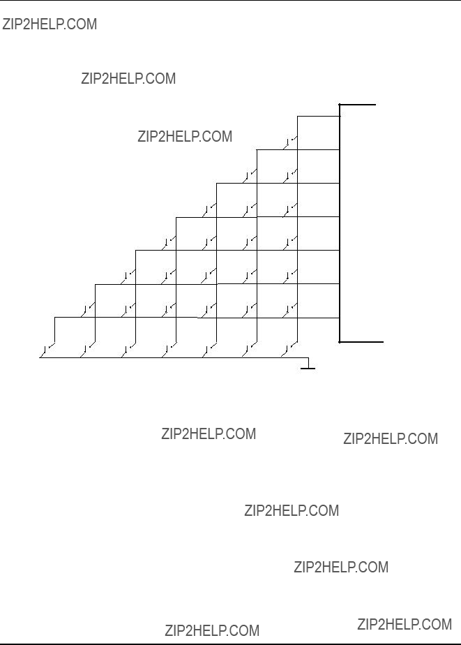
The fixed keyboard (See Figure 6) is scanned every 10 milliseconds. To scan the keyboard, the lines are made low - one at a time - and then the state of the other lines are read. For debouncing, a keypress must be detected 3 times before it is accepted.
36

Philips Semiconductors
Pins
37

Philips Semiconductors
4.2Factory options
4.2.1Diode options
The following options can be selected by means of option diodes:
1
2
3
4
5
6
7
8
9
1 0
1 1
D1 
Figure 5 Connection of Option Diodes
38

Philips Semiconductors
CCR612S will detect the following options automatically:
Digital sound control chip.
Presence / absence of a sound control chip (TEA632x) is detected by testing its I2C bus address. NOTE: The output pins AUMUTE, LOUDN and TA are always operational, even when a digital sound control chip is installed. Cassette solenoid and AMS pause control functions are not available in case no TEA632x is installed.
Presence of the
4.3I2C bus addresses
CCR612 I2C bus peripherals will be accessed at the following addresses:
C4 h PLL synthesizer TEA6811V
C2 h IF system TEA6822T
80 h Sound control circuit TEA632x
A0 h NVM PCF8594
(The PCF8594 responds automatically to address A2 h for access to its upper half); 40 h I/O expander PCF8574
70 h Display driver PCF8576
4.4The keyboard
Two different configurations are possible:
1.A fixed keyboard, directly connected to the microcontroller.
2.A detachable keyboard, using an I/O expander to connect to the microcontroller via a dedicated I2C bus. A fixed keyboard with a limited number of keys still remains possible.
39
Philips Semiconductors
4.4.1Fixed keyboard
The fixed keyboard is scanned every 10 milliseconds. For debouncing, the same situation must be detected 3 times before it is accepted.
Figure 6 Fixed keyboard
4.4.2Detachable keyboard
The detachable keyboard is scanned every 20 milliseconds (10 msec. for the small fixed keyboard). For debouncing, the same situation must be detected 2 times (3 times for the small fixed keyboard) before it is accepted.
The microcontroller will automatically detect that the detachable front is removed, and will switch the radio off. Placing the front on the radio does not cause the radio to switch on.
40
Philips Semiconductors
Figure 7 Detachable keyboard
4.4.3Keyboard options
Not all keys need to be installed. The following options are possible:
Preset select options
1.
The function AMS is available in this case.
SHUFFLE DISC, REPEAT TRACK, SHUFFLE ALL and REPEAT DISC are available now.
2.
The function AMS is not available in this case.
SHUFFLE DISC, REPEAT TRACK, SHUFFLE ALL and REPEAT DISC are not available now.
41

Philips Semiconductors
The following keys are optional. If omitted, the related functionality is not available, but other functions are not affected.
-DISPLAY
-PTY
-MUTE
-MODE
-SCAN
-LOCAL/DX
By means of an option diode, a selection can be made for a momentary power key (connected to port KEYB0 and ground) or a static on/off key (connected between port IGN and ground).
4.5Power stabilizer interface.
For switching the radio on and off, the microcontroller is linked with the voltage stabilizer circuit TDA3602. The pins involved in this interface are RESET, ON and HOLD.
Figure 8 shows a circuit diagram of the reset circuitry and the voltage stabilizer interface.
The TDA3602 has a number of different states, which are selected by the voltage on the state control input Vsc on pin 4. The following states are used:
To switch the radio on, the voltage stabilizer must be brought in reset state. It generates a reset pulse for the microcontroller with its reset output pin. The microcontroller program starts, and decides whether the radio must stay on or must switch off again. When it must stay on, output pin "ON" is pulled low, bringing the TDA3602 in the "ON" state. Else, the stabilizer stays in reset state, or returns to coma state eventually.
42

Philips Semiconductors
The reset pulse for the microcontroller must be at least 20 msec. wide, measured at the threshold level (max. 3.5 V).
After the end of the reset pulse the power key is sensed and the "KEYB0" output is pulled low to keep the stabilizer into the reset mode.
When the radio should stay on, (see switching on and off, paragraph 6.1), the "ON" output is pulled low after the check of the option diodes and when the power key is released.
After approximately 400 msec., the microcontroller tests the HOLD input. If it is low, something is wrong and the set is switched off, but internally a reset will be generated and the set will try to switch on again. Else it is continuously monitored for supply voltage failure e.g. starting the cars engine.
Figure 8 Interface with TDA3602 Power stabilizer
Note,
The power key is a momentary
43

Philips Semiconductors
4.6LCD display.
The LCD display is a 143 segment display, with a character set that includes umlaut (??) characters.
The display consists of the following fields:
-Text field for 8
-Numerical digit for display of the preset number;
-15 Icons for: REG, EON, AST, SCAN, LOC, AF, TP, ST, TA, PTY, LOUD, DOLBY, CLIP, MTL, AMS.
Figure 9 shows a possible layout of the LCD display
D
Figure 9 Liquid Crystal Display (LCD)
The 143 segment display is driven by one PCF8576 operating in 1:4 multiplex mode (4 backplanes BP0, BP1, BP2 and BP3) and a 1/4 (4 levels) LCD bias configuration.
44

Philips Semiconductors
Appendix II defines the connection of the segments of the display. Appendix III shows the character set. Figure 10 shows a diagram of the LCD driver interface.
Figure 10 Display module for 143 segments with PCF8576
4.7Non Volatile Memory.
This device is a 512 byte static CMOS EEPROM with
Figure 11
Appendix I shows the layout of data in the NVM.
45

Philips Semiconductors
5 KEY FUNCTIONS
In the following table External mode is:
TA LVL
46

Philips Semiconductors
-If the radio is in
-If the radio is in MW band, it switches to
-In other bands, nothing happens.
In the new band, the radio selects the preset or frequency that was last used in that band.
When pressed longer than 2 seconds (until the radio bleeps):
47

Philips Semiconductors
(continued)
Automatic tuning mode:
The radio will increase/decrease the frequency until a new station is found. At the end of the band it will wrap around and continue on the other side. If after one bandsweep no stations are found and in Local mode the radio will switch to Dx mode, the search then will stop after one complete sweep in Dx mode.
In FM:
- When TA mode is on, the search will only stop at traffic stations.
Manual tuning mode:
The radio will increase/decrease the frequency as long as the
In user option programming mode, the
48

Philips Semiconductors
(continued)
SCAN
INTRO SCAN
DISC SCAN
P1 - P6
AMS
MTL
DOLBY
In
In
Frequency Scan. Continuous automatic search tuning, pausing for 6 seconds on every station found.
The search direction is always search up and the algorithm is the same as for the normal search, see keys
In
In
When pressed short, these keys select a preset programme directly. The AF follow mode on/off state will be set according to the state stored in NVM.
When pressed longer than 2 seconds (until the radio bleeps), these keys serve to store the current station in preset memory. In FM, the state of the AF follow mode on/off switch is stored together with the frequency. Also the RDS PI code, programme service name and AF list are stored.
In cassette mode, some of these keys have additional functions:
-P4 Switch the AMS function on/off. When on, the AMS icon is on.
-P5 Switch MTL mode on/off. When on, the MTL icon is on.
-P6 Switch DOLBY on/off. When on, the DOLBY icon is on.
49

Philips Semiconductors
(continued)
DISC DOWN
DISC UP
SHUFFLE DISC
REPEAT TRACK
INTRO SCAN
SHUFFLE ALL
REPEAT DISC
DISC SCAN
In
-P2 Move to the next available disc
-P3 Move to an eventual previous disc
-P4 Switch the
-P5 Switch the
-P6 In
In
-P4 Switch the
-P5 Switch the
-P6 In
50
Philips Semiconductors
When pressed short, these keys are used to step to the next/previous preset programme. The AF follow mode on/off state will be set according to the state stored in NVM.
When pressed longer than 2 seconds (until the radio bleeps), the current station is stored in the last selected preset number. In FM, the state of the AF follow mode is stored together with the frequency. Also the RDS PI code, programme service name and AF list are stored.
When
1.A blinking preset number will be displayed.
2.Press
3.Press either
In cassette mode, these keys have additional functions:
When on, the DOLBY icon is on.
In
DISC UP
DISC DOWN
PTY
This key is active only if the radio is in FM.
When pressed the current received PTY code is displayed. In case no PTY code is received, "NO PTY" is displayed.
The user can now select a PTY code with
The PTY scan is started by pressing the PTY key for 2 seconds (until the radio bleeps). A search is started for the selected PTY code.
When a PTY code is received the PTY icon is on.
When a PTY search is busy, the PTY icon is blinking.
51

Philips Semiconductors
When TA mode is on, and a traffic announcement is transmitted:
-If the radio is muted, it will be
-If the radio was in cassette or external mode, it will switch temporarily to radio mode.
-Temporary switch over to an EON linked station when EON detects a traffic announcement on that other station.
-If the volume setting was very low, it will be raised temporarily. If the user does not change the volume setting, it will return to the original value at the end of the traffic announcement.
-The TA icon (and the EON icon in case of EON TA) will blink.
The current traffic announcement can be cancelled by pressing the TA key, the TA mode will not be switched off. This can be useful to cancel for example an unwanted EON traffic announcement.
The radio will automatically start a search when switching on TA mode and the current station is not a traffic station.
52

Philips Semiconductors
The state of the AF follow mode is displayed by the AF Icon:
When AF follow mode is on, the radio will from time to time measure the signal strength of the alternative frequencies that come with the RDS data. The interval between measurements depends on the signal strength of the current station, in the order of 1 minute for strong stations to a few seconds for weak stations. When the radio finds an alternative frequency that is - in several successive measurements - stronger than the current frequency, it switches over to that frequency.
53

Philips Semiconductors
The fader function is only available if the 2/4 loudspeakers option in the user programmable options was set to "4 SPKRS".
By default, the
54

Philips Semiconductors
In this mode the user can select the next options: -
(in
- Loudness on/off,
(alternative for the loudness key, if loudness option is available). - TA volume (A selection can be made of 5 different sound levels for
traffic news and PTY alarm messages This option is skipped when no digital sound control chip is installed).
RESET
MUTE
When pressed longer than 4 seconds (until the radio bleeps):
Performs an analogue reset function: bass, treble, balance and fader are set to
This key serves to switch the "muted" state on/off.
When muted:
-All audio output is suppressed
-The text "MUTE" is displayed.
-In cassette mode the cassette player will be stopped.
-In
The muted state is switched off, when the mute key is pressed again, or when any other key is pressed. The muted state will be temporarily suspended when the radio is in TA mode and a traffic announcement is received, or when a PTY alarm message is received.
55

Philips Semiconductors
Each time the key is pressed, the next input source is selected in the order: radio
with the restrictions:
-
-Cassette is selected only if a tape is present in the cassette deck.
-External is selected only if a connector is inserted in the external input jack.
56

Philips Semiconductors
6 FUNCTIONAL DESCRIPTION
6.1Switching on / off
To switch the radio on, a reset pulse must be applied to the microcontroller. The software will then perform a number of checks, and may either turn on all voltages, or switch the radio off again.
With a bad battery, the voltage may drop so far that the "HOLD" output of the voltage stabilizer goes low, e.g. during starting of the cars engine, and the radio switches off. The radio will switch on immediately when the voltage returns to a normal value.
If the radio was previously switched off by turning the ignition off, it will switch on when the ignition key is turned on again.
The radio can also be switched on with the power key while ignition is off. In that case a sleep timer is started that turns the radio off after 60 minutes unless ignition is switched on in the mean time.
The table below shows the differences between the static on/off switch and the momentary power key.
57

Philips Semiconductors
6.2Tuning
6.2.1Band switching
Band switching can be done with the AST and BAND keys (see Figure 12). In the AST bands, the AST icon is on. Band switching is only accessible in Radio Mode.
LW
B A N D
Figure 12 Band selection
6.2.2Manual/search tuning
Figure 13 shows how to switch between the tuning modes. In preset mode, a preset number is shown on the display. In other modes, no preset number is shown. When leaving preset mode, any update of preset data (current frequency, PS name, AF list, AF follow mode bit) is stored in NVM. Switching of tuning mode may be done either by pressing
When key
First tuning step
-
-Frequency step size:
SW LW MW FM
58
Philips Semiconductors
Repetitive steps (after 0.5 sec)
-12.5 steps/sec
-
-Frequency step size:
SW LW MW FM
PRE UP PRE DOWN
PRESET
M O D E
PRE UP PRE DOWN
1 2 3 4 5 6
AUTOMATIC
SEARCH
M O D E
AUTO /MAN
 A UT O / MA N
6 sec timeout
MANUAL
TUNING
M O D E
Figure 13 Tuning modes
In search tuning mode, after pressing the
-search sensitivity Local (high signal level) or Dx (low signal level).
-Ta mode on, the search will only stop at traffic programmes.
When the radio is in Local mode and after one band sweep no station was found, the search sensitivity is switched to Dx. If still no valid station can be found, the radio returns to the frequency from which the search was started.
Depending on these criteria a maximum of two band sweeps will be made, trying to offer a frequency fulfilling the search criteria.
For FM, a Local / Dx switch is incorporated in the TEA6811. Putting the radio in Local mode results in an attenuation of the aerial signal with 15 dB. For AM, the signal levels read back from the TEA6822 are used to create the Local /Dx functionality. In AM mode, the search stop level for Local is set 22 dB higher than when the radio is in
During a tuning action - manual or automatic - the display will show the running frequency at any time.
59

Philips Semiconductors
6.2.3Frequency scan
The frequency scan mode enables the user to listen to all stations transmitted in the selected band (FM, MW, LW or SW). The radio pauses for 6 seconds on every station found before search is started again. During frequency scan, TA mode is included in the stop criteria in the same way as during normal search. EON traffic announcements are skipped during frequency scan mode.
Frequency scan is cancelled by every other tuning function. The radio will switch to the last valid station when the cancelling takes place during search. Frequency scan mode is only accessible when the radio is in Radio Mode.
6.2.4Selecting preset stations
In each band, there are 6 presets. To select a preset station:
If the radio is equipped with 6 preset selection keys (P1 - P6) - Press short on the key of the desired station.
If the radio is equipped only with
- Press either
If initially no preset number was displayed, the first preset selected will be the last preset number used in the band.
Selecting preset stations is only accessible in Radio Mode.
6.2.5Storing stations in preset memory
If the radio is equipped with 6 preset selection keys (P1 - P6)
-Press key of the preset number to be stored until the radio bleeps (2 seconds). The station is now stored.
If the radio is equipped only with
-If the current preset number is the desired preset number:
-Press either the
-If the current preset number is not the desired preset number:
-Press keys
-Press either
-Press either the
The preset store mode is cancelled when the
Storing stations in preset memory is only accessible in Radio Mode.
60
Philips Semiconductors
6.2.6AST search
To start an AST (Automatic Store Tuning) search, press the AST key until the radio bleeps (2 seconds). Now, the following actions are taken:
1. If the radio is not in an AST band, it switches to the relevant AST band
AST is not available in the LW and SW bands.
2.The 6 strongest stations will be stored in the NVM, ignoring TA mode. The whole band is scanned for transmitters, a maximum of two sweeps will be made, one in Local mode and if necessary one in Dx mode). If less than 6 stations were found, the last preset memory locations are not replaced.
3.
During the whole process, the radio is muted and the message "STORE" is shown on the display unless the radio is in
6.2.7The LOCAL/DX key
The user can control the search sensitivity of the radio via the so called Local/Dx feature. In Local mode, the radio will only stop at strong stations. In Dx mode, a search action will also stop at weaker stations. The Local/Dx status is displayed via an icon. After power on, the radio will always go in Dx mode.
When the radio is in search tuning mode the tuner Local/Dx status depends on the Local/Dx setting. As soon as the radio is in stable tuning condition the tuner attenuator status will be Dx.
6.3
CCR612 is equipped with five different audio sources (radio,
Automatic selections can be overruled by the MODE key.
When the radio is switched off, the source select state is stored in NVM. The same state is selected again when the radio is switched on.
61

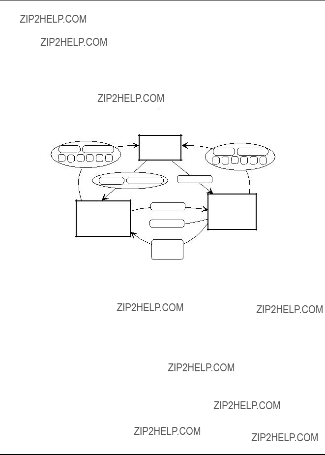
Philips Semiconductors
Figure 14 Source selection by external event.
6.3.1The MODE key
Automatic source selection can be overruled by using the MODE key. Each time the MODE key is pressed, the next source is selected in the order:
Radio
Cassette mode can be selected only if a tape is present in the cassette deck.
External mode can be selected only if a connector is present in the external audio jack.
6.3.2
The presence of a
While in
TABLE Key mapping in
62

Philips Semiconductors
6.3.3Cassette functions
The cassette interface is based on a mechanical tape deck. When a cassette is playing, the display will show the text "PLAY >" or "PLAY <" indicating the play direction. During fast winding, no direction information is available. The display will show "CAS WIND". When fast winding for more than 4 seconds, the set will temporarily switch to radio mode.
While in cassette mode, the keys
The state of the AMS, ME/CR and Dolby functions is displayed by icons. If a TEA632x is installed the cassette solenoid and AMS pause function are available. The solenoid function takes care of playing in the correct direction after switching to cassette mode and together with the AMS pause function, it takes care of controlling the AMS function. Search (in both directions) for the next music piece by detecting a blank area on the tape. If no TEA632x is installed (potentiometer sound control) the AMS function and the solenoid function are not available. If the cassette drive does not have the AMS function the CAMS pin must be connected to ground.
6.3.4External audio source
An external audio input is available to connect e.g. a CD player. The external input jack has a switch to sense whether a connector is inserted. While the radio is in external mode, the text "EXTERNAL" is shown on the display. When no external audio selection is available the EXSTAT pin must be connected to Ground.
6.4Audio control
Most of the audio control facilities are available only if a digital sound and fader control chip (Sofac) is installed. If no digital sound control chip is used, the following signals should be used in combination with potentiometer control:
The volume at power on is limited to
63

Philips Semiconductors
6.4.1The SELECT key
By default, the
VOLU ME S E L E C T
Figure 15 Selection of sound control functions
6.4.2Changing a setting
To change a setting, press the
The volume setting is not shown on the display. Other functions are shown on the display(e.g. BASS +6).
6.4.3The LOUD key / RESET function
Loudness is switched on/off by pressing the LOUD key short. When loudness is on, bass and treble are added to the audio signal, depending on the volume level. The loudness function is carried out by the TEA632x. If no TEA632x is installed the loudness function is carried out by external loudness circuitry controlled by the LOUDN pin. The loudness on off status is displayed via an icon. When the loudness key is pressed for 4 seconds (until the radio bleeps), the reset function is executed. This function sets bass,
64

Philips Semiconductors
treble, balance and fader to
6.4.4The MUTE key
When the mute key is pressed, all audio output is suppressed, and the display will show the text "MUTE". Any keypress will cancel the mute state. The audio control settings are not altered. When TA mode is on and a traffic announcement or a PTY alarm message is broadcast, the mute state is temporarily suspended.
6.4.5Phone mute
When pin Aumute is pulled to ground externally by a connected car phone, the car radio sound is muted and the display will show "PHONE".
6.4.6Power ampli??er diagnostics control
CCR612 can be equipped with power amplifiers with a diagnostics interface. This interface consists of one pin which is low at erroneous situations. CCR612S will continuously monitor this pin and can detect one of the following situations:
Clipping
-The bass and or volume level will be decreased depending on the amount of clipping.
-While clipping is detected and clipping control is active the clipping icon is on.
Too high temperature / short circuit
-CCR612 will display the error message "ERROR" on the LCD.
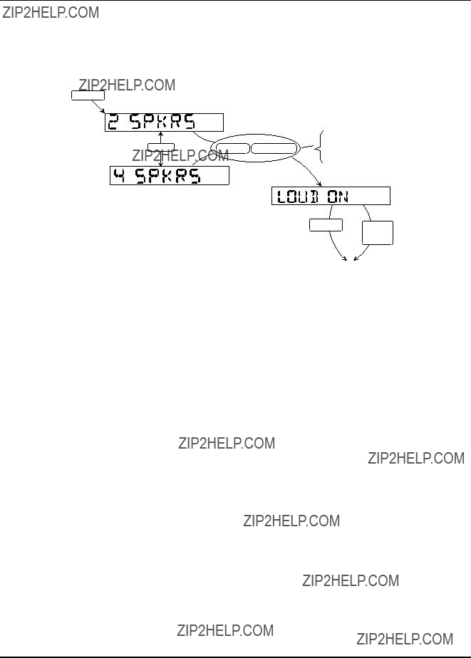
6.4.7User programmable options
Some options can be programmed by the user. The options are stored in NVM, and remain in effect until reprogrammed by the user. The options are:
2 SPKRS / 4 SPKRS
Indicates how many loudspeakers are connected to the radio. If "2 speakers" is selected, the fader function is not available, and fader setting is always
LOUD ON / LOUD OFF
If no loudness key is installed, loudness can be switched on/off using this option in case the loudness function is available.
TA LVL
The volume level during a Traffic Announcement or PTY Alarm can be set to one of 5 fixed values varying from
65
Philips Semiconductors
S ELECT
> 4 seconds
Figure 16 Programming user options
6.5RDS / RBDS functions
The RDS / RBDS functions are available only if the radio is tuned to an FM band.
6.5.1AF follow mode
The AF follow mode mechanism is switched on/off by pressing the AF key short. When AF follow mode is on, the AF icon is switched on. If no RDS data is received, the AF icon blinks.
In AF follow mode, the radio measures at regular intervals, (interval time depends on the signal quality), the signal level at frequencies that are mentioned in the list of alternative frequencies (AF's) for the current station. For these measurements, the reception of the current station is interrupted for a very short period (appr. 7 milliseconds), and it is hardly noticeable. If an alternative frequency is stronger than the current station for a few seconds (depending on the signal quality), the radio switches to that alternative frequency. It switches also if the quality of the current station becomes suddenly very poor, or if its RDS data cannot be received. The quality of a station is a function of signal level as well as multipath condition.
The AF follow mechanism is always active when AF follow mode is on, even when the radio is muted or is in
When the user starts a tuning action (band, preset,
66

Philips Semiconductors
6.5.2PTY functions
CCR612 offers the user the possibility to search for a station with a certain user selected PTY code. When key PTY is pressed, the currently received PTY code is displayed. If no PTY code is received the display will show "NO PTY" . By pressing the key
RBDS
N EW S
INF ORM
SPO RTS
TAL K
R OC K
CLS ROCK
ADL T HIT
SOF T RCK T OP 4 0
COUNTRY
OL DIES
SO FT
NOSTAL GA
J AZZ
CLASSICL R & B
SOF T R&B
L ANGUAGE
REL MUSIC
REL TAL K
PERSNL TY
PUBL IC
TE ST
ALERT!
Figure 17 Selecting the PTY code
PTY codes "ALARM" / "TEST" / "ALERT!" can not be selected. The radio will respond to a PTY alarm message in the same way as a TA traffic announcement, independent of TA mode. For the USA application the RBDS PTY table is used.
During a PTY search the PTY icon blinks. When the radio receives a PTY code, the PTY icon is on. When TA mode is on during a PTY search, the radio will first try to find a station which is a traffic station with the correct PTY code. When no such station can be found (even not in Dx mode), the radio will drop
67

Philips Semiconductors
the TA requirement and search only for a station with the correct PTY code. If still no station can be found, the radio will return to its original tuned frequency.
6.5.3Traffic announcements
Traffic announcements have a special meaning only when TA mode is on.
To switch TA mode on/off, press the TA key. When TA mode is on, the TA icon is on. If the current station is not a traffic station, the TP icon blinks, and a warning bleep is generated every 30 seconds.
If TA mode is on, the next happens when a traffic announcement is broadcast:
1.If the traffic announcement is detected via EON, the radio will switch to the linked programme service transmitting the traffic announcement. The radio will stay at least 4 seconds on this programme before switching back to the original programme to give the broadcaster time to synchronise the RDS TP and TA data over its network.
AF follow mode is disabled during an EON traffic announcement.
2.If the radio is in
3.If the radio is muted, it is temporarily
4.If the volume was low, it is raised to the TA volume level as installed under the user options (see: user programmable options). Also, the TA output pin is made low.
5.The TA icon blinks. In case of a traffic announcement on an EON linked station, the EON icon will also blink.
At the end of the traffic announcement, the old situation is restored again (after an EON traffic announcement the radio will switch back to the original station). If the user has not changed the volume setting, it is restored to the value before the traffic announcement. If the volume level was changed, the new value will be retained.
The current traffic announcement can be cancelled by pressing the TA key, the TA mode remains on.
6.5.4PTY alarm broadcasts
A PTY alarm message is treated the same way as a traffic announcement. A PTY alarm message will
68

Philips Semiconductors
7 RDS / RBDS FACILITIES.
As soon as the radio is steadily tuned to an FM station, it will start collecting RDS information. The next items are extracted from the stream of RDS data:
Most data is validated, e.g. the same data must be received twice before it is accepted as a new value.
7.1Programme Identi??cation code
The PI code is invisible for the user. It is used to check whether the correct station is received after a preset is selected, or when the AF follow mechanism switches to an alternative frequency.
When a station is stored in NVM, also its PI code is stored. When the same preset is selected again, the radio verifies the PI code. If the PI code is not correct, and AF follow mode is on, the radio will search for a station with the right PI code, first by scanning all available alternative frequencies, then if after a timeout of 6 seconds the PI code is still not correct, a search tuning operation is started.
During AST Search, the PI code is used to avoid that the same programme is stored at different presets, when it can be received on more than one frequency. For USA application (RBDS) the regional function will only work for PI codes above B000hex. PI codes below B000hex do not have regional variants. AF switching is only allowed to stations with exactly the same PI code.
7.2Programme Service name
By default, the radio will display the received Programme Service name as soon as it is available. The PS name is stored in the preset memory locations. The name is then immediately displayed when a preset station is selected.
Tuning frequency instead of PS name is displayed when the radio is in manual tuning mode. Also, by means of the display key, the radio can be forced to display PTY code, frequency and PS name respectively.
7.3Programme TYpe
PTY is a code for the kind of programme that is broadcast. Figure 17 shows the names of PTY codes that are defined for RDS. CCR612 can display the PTY currently received, and it can search for a station with a specific PTY code. The user can select a PTY code and start a scan for a station transmitting this PTY code.
69

Philips Semiconductors
7.4Traffic Announcements
RDS data contains two bits called TP (Traffic Programme) and TA (Traffic Announcement), see the table below for the meaning of these bits.
The radio will start a search for a traffic station when the TA mode is switched on when the current station is not a traffic station.
If TA mode is on, and the current station is not a traffic station, the TP icon will blink, and a warning bleep is generated every 30 seconds.
If a traffic announcement is received while TA mode is on, and the radio is in
If a traffic announcement is received via EON (RDS group 14B is received indicating the PI code of the other station transmitting the traffic announcement), the radio will check its internal pool store and will try to switch over to the other station transmitting the traffic announcement. The radio will stay on this other station for at least 4 seconds to give the broadcaster time to synchronise the RDS TP and TA data over its network.
By pressing the TA key the current traffic announcement will be cancelled but the radio remains in TA mode.
If during a traffic announcement the signal quality becomes too weak resulting in the fact that RDS reception is lost, CCR612 will cancel the traffic announcement after a timeout of 2 minutes.
7.5Alternative Frequency following
The radio will always assemble a list of alternative frequencies from the received RDS data, even when AF follow mode is off. When the current frequency is left (by tuning, band switching or by turning the radio off), the alternative frequency list is stored in NVM if it is different from the previous stored list.
70
Philips Semiconductors
1.When selecting a preset, the radio will load the AF list from NVM, and measure the signal strength of the primary frequency and all alternative frequencies. It will then select the strongest station with the correct PI code, before the radio is
(PI codes are compared with the value stored in the preset data in NVM.)
If no station with the correct PI code is found, after 6 seconds the radio will start a search tuning for a station with the correct PI code. If still not found, it will accept the new station, but it will not update the PI code stored in NVM.
Search tuning can be cancelled by switching AF follow mode off or by pressing the AUTO / MANUAL key. The radio will then return to the original frequency.
2.At regular intervals - depending on the signal strength of the current station - the signal strength of alternative frequencies is measured. The interval varies from appr. 80 seconds when the signal level of the current station is very strong to appr. 3 seconds when it is very weak.
3.When for a certain time an AF is stronger than the current frequency, or when the current frequency becomes suddenly unacceptable e.g. due to multipath, the radio switches to the best alternative frequency.
When the programme service is left (by tuning, band switching or by turning the radio off), the new frequency is stored in NVM as the primary frequency for that preset.
The AF follow algorithm has provisions for special circumstances such as:
-Mountains and buildings. All signal strengths vary rapidly due to multipath distortion. Switch when the multipath distortion level becomes unacceptable.
-Loss of RDS data or station changes PI code. Select an alternative frequency with correct PI code.
The "quality" of a station is a value that is based on signal level as well as multipath level read from the TEA6822 by means of the
7.6EON preset update
When the tuned station transmits EON information, the alternative frequencies stored for the station presets are updated via EON. Only those alternative frequency lists of station presets can be updated whose PI codes match one of the PI codes transmitted via EON. Whether or not regional variants of the PI code are taken into account depends on the status of the regional selection. If the regional selection is switched on, the transmitted PI code must exactly match the PI code to update.
If after travelling any distance while tuned to a programme service, a user selects a preset for another station which is
71

Philips Semiconductors
Words (16 bits) are stored with the most significant byte first (in lowest address).
Ordering of the bits in a byte or word:
Bit 0 is the least significant (rightmost) bit
Bit 7 is the most significant (leftmost) bit of a byte
Bit 15 is the most significant (leftmost) bit of a word
Layout of NVM
72

Philips Semiconductors
73

Philips Semiconductors
74

Philips Semiconductors
75

Philips Semiconductors
76

Philips Semiconductors
Segment addresses for the used (143) segments. Note that BP0 and BP3 are swapped.
77

Philips Semiconductors
78

Philips Semiconductors
Figure 18 LCD Character Set
79

Philips Semiconductors
80
Philips Semiconductors
81

Philips Semiconductors
82

Philips Semiconductors
83

Philips Semiconductors
84

Philips Semiconductors
85

Philips Semiconductors
86

Philips Semiconductors
87

Philips Semiconductors
88

Philips Semiconductors
89

Philips Semiconductors
90
Philips Semiconductors
91

Philips Semiconductors
92

Philips Semiconductors
93

Philips Semiconductors
94