Installation and Operating Instructions

Gas Instantaneous Water Heater

W11..P...

W14..P...

W18..P...

With piezo ignition and double safety system consisting of flue gas monitor and heat exchanger temperature sensor.

6 607720 ZA526 .(05 JS02)

Safety instructions:

If you smell gas:

-Do not operate any electrical switches.

-Do not telephone from inside the danger area.

-Turn off the gas cock.

-Open windows and ventilate room.

-From outside, call the gas company and your approved installer.

Do not use or store easily combustible materials in the vicinity of the appliance.

Installation and servicing of the appliance may only be carried out by an approved technician.

The appliance should be regularly serviced in order to ensure that it remains in perfect and safe working order.

If there is a risk of freezing, the appliance must be switched off and drained. If the appliance has not been drained during a cold spell, when it is switched on again check that it produces hot water. If problems occur, contact your installer.

Index

1.Technical Characteristics and Dimensions

1.1General Description

This water heater is fitted with a piezo system. Guaranteed safety provided by:

-Gas-tight ionisation detector that prevents escape of gas if there is no flame.

-Flue gas safety device that switches off the appliance if the flue is not functioning properly.

-Temperature limiter which protects the heat exchanger against overheating.

Heat exchanger has no tin/lead lining.

Automatic water valve made of glass-fibre reinforced polyamide, 100% recyclable.

Automatic control of water flow maintains constant flow rate even with fluctuating supply pressure.

Gas valve with adjustable output via a slide control.

1.2Explanation of Model Code

W Gas instantaneous water heater 11 Flow rate (l/min)

P Piezo ignition

23 Natural gas type H

31 LPG (butane/propane) S... Country code

1.3 Accessories (Included with Appliance)

- Sleeves and hooks for wall-mounting

1.4 Dimensions

1. Front cover

2. Hole for fixing to wall

3. Observation window

4. Temperature control

5. Output control

6. Gas connection

7. Exhaust pipe union

8. Draught diverter with flue gas monitor

9. Heat exchanger

10. Automatic gas valve

11. Piezo

12. Water valve

Fig. 2

1.5Appliance design

1.6Technical characteristics

**This figure must not be exceeded taking account of water expansion

***At maximum rated heat output

2.Preconditions for installation

The appliance can only be sold in the countries mentioned in the type plate.

2.1Regulations

Any local by-laws and regulations pertaining to installation and use of gas-heated appliances must be observed. Please refer to the laws that should be attended in South Africa.

2.2Location

The appliance should be sited in a well ventilated room where it will not be exposed to temperatures below freezing.

To prevent corrosion, the combustion air must not contain any corrosive substances. Substances classed as corrosion- promoting include halogenated hydrocarbons such as are found in solvents, paints, adhesives, aerosol propellants and various household cleaners. Appropriate measures should be taken where necessary.

With the exception of the flue pipe, the surface temperature of the appliance is below 85 ??C. No special safety measures are therefore necessary.

Site appliance as shown in Fig. 4.

Always site appliance in a location not exposed to temperatures below freezing. If this is not possible, the appliance must be switched off and drained whenever there is a risk of freezing.

Danger: the appliances are designed to prevent flame reflow. In case you suspect anything unusual in the appliance operation, please shut down gas and water cocks, and call an approved technician to check the local conditions.

To prevent flame reflow in outdoor installations please make sure that a wind/rain protection is fitted.

To prevent flame reflow in indoor installations please make sure that a wind/rain protection is fitted at the end of the secondary flue.

2.3Fixing the appliance

Remove the temperature control and the output control. Remove the outer case by sliding it forwards and then lifting upwards.

Fix the appliance using the sleeves and hooks supplied so that it is vertical.

Never allow the appliance to rest against water or gas pipes.

2.4Water connection

It is advisable to drain the appliance before installing it as any dirt or grit inside it could reduce the water flow rate and, in extreme cases, could completely clog up the appliance. Mark hot water and cold water pipes so as to prevent confusion.

Connect pipe to automatic water valve using the connecting kit supplied.

To prevent problems caused by sudden pressure fluctuations in the water supply, it is advisable to fit a non-return valve to the water outlet.

2.5Gas connection

Take care to ensure dirt is not allowed to enter gas inlet. Make sure that the type of gas specified on the appliance type plate is the same as that supplied by the gas authorities.

Select pipe diameter to suit output of instantaneous water heater being installed.

Fit gas service cock as close to appliance as possible.

Caution: This is a low pressure gas appliance. A SA certified 2.8 kPa low pressure regulator must be fitted.

2.6Flue

It is absolutely essential that all instantaneous water heaters are connected to a suitably dimensioned flue pipe by means of a gas-tight connection.

The flue pipe should be made of galvanised iron, aluminium, stainless steel or fibre concrete. Fit as shown in Fig. 4.

A flexible or rigid pipe should be used, fit it inside the flue socket. The external diameter of the pipe should be slightly smaller than the dimension specified in the appliances dimensions table.

wind/rain protection

Fig. 4

2.7Commissioning

Turn on the gas and water cocks and check all connections for leaks.

Check flue gas safety device good functioning, proceed as explained in section 3.5.

3.Operation and maintenance

Sealed parts must not be interfered with.

3.1Function

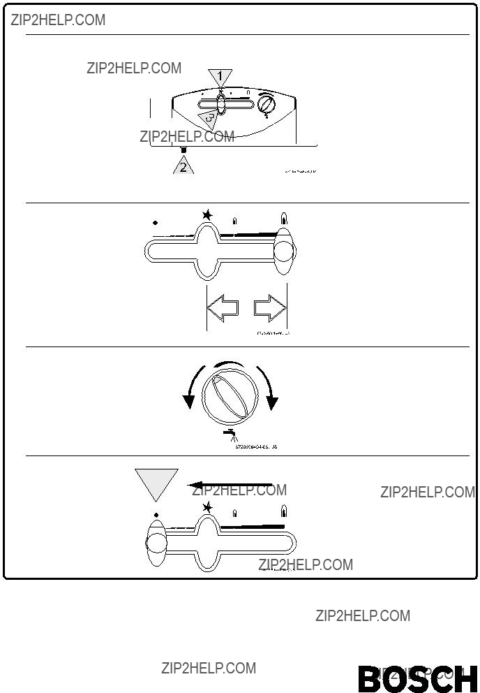
This water heater is fitted with piezo ignition that provides for easy commissioning.

In first place it must dislocate the output control of the off position to the ignition position (see fig. 5).

Press in the slide control knob and subsequently press the piezo button. Release the slide control after about 15 seconds, if the pilot flame does not stay alight, repeat the operation.

Ignition may not be successful due to the presence of air inside the gas supply pipe, especially if first connected or after long inactive periods. In this case, keep the output control knob fully depressed until the gas pipe has been totally purged.

Slide the gas control slide fully to the right to obtain maximum output. Sliding the gas control slide to the left reduces the output.

In order to optimise energy consumption, adjust the output control to supply the minimum output required.

After following these procedures, ignition of the main burner will automatically take place whenever you turn on a hot water tap, since the pilot burner is permanently alight.

When you want to switch off the heater, move the slide control to the far left. After a few seconds the pilot flame will go out.

If there is a risk of freezing, switch off the appliance and drain the appliance.

Danger: the area in front of the burner can reach very high temperatures, and there is a risk of burning on contact.

3.2Water temperature control

The water temperature control is used to adjust the water flow rate, and thereby the water temperature, to the desired setting.

Turning the control clockwise reduces the water flow rate and increases the temperature; turning the control anti- clockwise increases the water flow rate and reduces the temperature.

If the temperature is set only as high as required, energy consumption is reduced and the likelihood of scale deposits in the heat exchanger minimised.

3.3Appliance adjustments

All instantaneous water heaters are factory-adjusted and require no further adjustment.*

Water heaters that use LPG (liquefied petroleum gas, i.e. butane/propane) are set to the operating pressure stated on the identification plate (2,8 kPa).

Natural gas appliances are set to a Wobbe Index of 15 kWh/ m3 and a supply pressure of 2.0 kPa.

* Sealed components must not be tampered with.
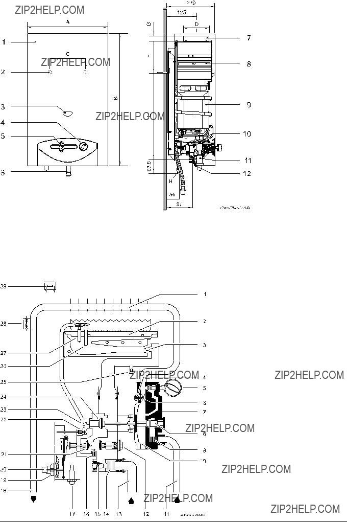
3.4Maintenance

The appliance should only be serviced by an approved engineer.

A complete overhaul should be carried out after two years.

The overhaul should involve thoroughly cleaning the heat exchanger, burner, pilot burner and automatic water valve filter.

If necessary, the inside of the heat exchanger and the connecting pipes should be descaled.

Check the gas and water valves for leaks and carry out a complete function check.

If components need to be replaced, use only genuine Bosch spare parts.

3.5Flue gas safety device

The recommition must be done from a qualified technician only.

The flue gas safety device must not under any circumstances be switched off, simulated or replaced by any other component.

Operation and safety precautions

The flue gas safety device checks the effectiveness of flue gas extraction by the flue. If it is inadequate, the appliance switches off automatically so that the combustion fumes do not escape into the room in which the appliance has been installed. The flue gas safety device resets after a cooling- down period.

If the appliance shuts down while in operation, ventilate the room. Wait about 10 minutes then restart the appliance. If the problem recurs, call an engineer. The user must never make any modifications to the appliance.

Maintenance

If faults occur on the flue gas safety device, proceed as follows:

-Undo flue gas safety device fixing screw.

-Undo magnetic unit connector

-Remove thermocouple.

Replace damaged component with new one and refit using the reverse of the procedure set out in the table above.

Function check*

Flue gas safety device function check:

-Disconnect flue pipe

-Replace with pipe (about 50 cm long) with sealed end

-Fit pipe vertically

-Start up appliance at rated output and set temperature control to maximum temperature.

Under those conditions, the appliance should shut down after two minutes. Remove temporary pipe and reconnect flue pipe.

* This work may only be carried out by an approved engineer.

3.6Converting to a different gas type

Use only the genuine Bosch conversion kit. Conversion may only be carried out by an approved technician.

3.7Troubleshooting

Installation, servicing and repairs may only be carried out by an approved engineer.

The following table illustrates only a few solutions to straightforward problems.

The operations marked with ???*??? may only be carried out by an approved technician

4.Operation

Turn on all gas and water taps

Purge air from pipes

Ignition:

Depress slide control knob and hold it in

Release the slide control knob after approximately 15 seconds

Press the piezo igniter

Repeat these steps if the flame does not stay alight

Output Control:

Temperature adjustment

Turning control anti-clockwise

increases water flow rate and reduces water temperature

Turning control clockwise

reduces water flow rate and increases water temperature

Switching off:

Move slide control to the far left

Fig. 5