Water heaters for use with Natural and L.P.G.

GWH-635-ES

Temperature Modulated with Electronic Ignition

Suitable for heating potable water only - Not approved for space heating purposes (Intended for variable flow applications with multiple tapping points)

6 720 607 072 (04.03) JS

Warning: If the information in this manual is not followed exactly, a fire or explosion may result causing property damage, personal injury or death. Do not store or use gasoline or other flammable vapor and liquids in the vicinity of this or any other appliance.

Improper installation, adjustment, alteration, service or maintenance can cause injury or property damage. Refer to this manual. For assistance or additional information consult a qualified installer, service agency or the gas supplier.

In the Commonwealth of Massachusetts this product must be installed by a licensed plumber or gas fitter.

Upon completion of the installation, these instructions should be handed to the user of the appliance for future reference.

What to do if you smell gas

???Close gas valve. Open windows.

???Do not try to light any appliance.

???Do not touch any electrical switch; do not use any phone in your building.

???If you cannot reach your gas supplier, call the fire department.

???Immediately call your gas supplier from a neighbor???s phone. Follow the gas supplier???s instructions

???Installation and service must be performed by a qualified installer, service agency or the gas supplier.

Index

9Special adjustment for measuring and adjusting CO2

Warning: Carefully plan where you install the heater. Correct combustion air supply and flue pipe installation are very important. If a gas appliance is not installed correctly, fatal accidents can result from lack of air, carbon monoxide poisoning or fire.

Warning: Exhaust gas must be vented to outside using proper vent material suitable for category III vent systems and temperatures up to 480??F. Vent and combustion air connector piping must be sealed gas-tight to prevent possibility of flue gas spillage, carbon monoxide emissions and risk of fire, resulting in severe personal injury or death.

Warning: Place the heater in a location where water leaks will do NO DAMAGE to adjacent areas or lower floors.

Warning

Warning: Field wiring connections and electrical grounding must comply with local codes, or in the absence of local codes, with the latest edition of the National Electric Code, ANSI/NFPA 70, or in Canada, all electrical wiring must comply with the local codes and the Canadian Electrical Code, CSA C22.1 Part 1.

Warning: Shock hazard line voltage is present. Before servicing the water heater, turn off the electrical power to the water heater at the main disconnect or circuit breaker. Failure to do so could result in severe personal injury or death.

FCC:

This device complies with Part 15 of the FCC rules. Operation is subject to the following two conditions: (1) This device may not cause harmful interference, and (2) this device must accept any interference received, including interference that may cause undesired operation.

Caution: Any changes or modifications not expressly approved by the party responsible for compliance could void the user???s authority to operate the equipment.

Fig. 2

Appliance details

2Appliance details

2.1Features

Parts

???Touch Pad interface control

???High power pre-mix compact burner with low Nox emissions

???Modulating Gas Valve with constant gas:air ratio control

???Modulating water valve for improved comfort and temperature control.

Safety

???Flame sensor (ionization) rod

???Overheat sensor

???Temperature limiter

???Fan speed monitoring.

High Quality Materials for Long Working Life

???Copper heat exchanger

???Ceramic Burner output

???Automatic overheating protection shut-off sensor

???Compact space saver: mounts on a wall with a supplied bracket.

???Easily removable one-piece cover.

Features

???LCD Display

???On/Off and Temperature control switches

???Reset button

???Program Key (Selectable temperature default)

???Failure codes for easy diagnostic and repair. Accessories

???Optional wireless remote control accessory to operate with the appliance

???Vent termination kit.

BOSCH is constantly improving its

iproducts, therefore specifications are subject to change without prior notice.

2.2GWH-635-ES Specifications (Technical data)

Approved in US/Canada

Capacity

Maximum flow rate: 6.35 GPM (24 l/min) at a 45??F (25??C) rise.

Maximum output

142,968 Btu/h (41.8 kW)

Maximum input

175,000 Btu/h (51.2 kW)

Efficiency in %

Recovery efficiency 86.5%

Min. Output

31,131 Btu/h (9.1 kW)

Temperature Control

Selection range: 100??F (38??C) - 140??F (60??C)

Default temperature: 122??F (50??C)

Stability: +/- 2??F (+/- 1??C)

Gas Requirement

Gas connection (inches) - ?????

Inlet gas pressure under operation (with a high hot water flow rate)*

???Propane: 11??? - 14??? water column

???Natural Gas: 5??? - 14??? water column

???Gas pressure measuring point inside the appliance at the gas valve inlet.

* Testing with a manometer, operate other gas equipment on the same gas supply. Gas pressures lower than 5" W.C. for Natural Gas or 11" W.C. for LPG will result in insufficient degree rise to the hot water being used. See Measuring Gas Pressure, chapter 2.12.

Fig. 3 Gas pressure measuring point

Venting

See chapter 2.9 for Venting on page 9.

Water

???Hot water connection (inches) - ?????

???Cold water connection (inches) - ?????

???Water valve material: Polymer (PPS) (Polypropylene Sulfid)

???Minimum water flow: 0.8 gallon/minute (3 l/m)

Appliance details

???Minimum recommended water pressure: 30 PSI (2.07 bar)

???Connections:

??? Bottom of heater

Combustion

???NOx ??? 55 ppm

???CO ??? 250 ppm

???CO2 level set from factory, see chapter 9.1.

Dimensions

???Depth (in): 8 ????? (220 mm)

???Width (in): 15 ????? (400 mm)

???Height (in): 23 ????? (600 mm)

???Weight: 47 pounds (21 kg).

Gas types

Natural Gas. LP Gas.

Converting the gas type can only be done by a certified gas technician with a calibrated CO2 analyzer. Call CEC for conversion instructions.

Voltage

120 V AC (50/60 Hz)

Amperage

IDLE - 40 mA

Operation - ??? 2,5 A

Noise

??? 50 db (A)

Safety devices

???Flame failure device (ionization flame rod sensor)

???Pressure relief valve (supplied with heater)

???Over heat prevention (temperature limiter).

Water resistant

IP X4 (protection against water drops)

UNPACKING THE GWH-635-ES HEATER

This heater is packed securely.

The box includes:

???Pressure relief valve

???Bracket for wall hanging the heater

???Exhaust vent adaptor (with 4 screws and gasket provided)

???Combustion air inlet adaptor (with 3 screws and gas- ket provided)

???Plastic decal shields for covering front cover screws and control panel, installer should affix these decals to the front of the unit after installation is complete. See Fig. 4

???Installation manual

???Product registration card.

Do not lose this manual. Please complete and return the enclosed product registration card.

Before installing the unit, be certain you have the correct heater for your type of Gas - Propane or Natural Gas. Identification labels are found on the shipping box, and on the rating plate which is located on the right side panel of the cover.

To remove front cover

???Loosen the two Philips head screws located on front panel (beneath plastic decal shields if they are already attached, see Fig. 4)

???Lift front cover panel upward and remove.

Plastic decals

Fig. 4 Remove front cover

Appliance details

2.3Dimensions and Minimum installation clearances

Fig. 5 Dimensions

1Cover

2On/Off switch

3 Reset button

4 LCD display

5Program button

6Temperature buttons

Fig. 6 Minimum clearances

Table 1 Minimum clearances

Appliance details

2.4General rules to follow for safe operation

B1. You should follow these instructions when you install your heater. In the United States: The installation must conform with local codes or, in the absence of local codes, the National Fuel Gas Code ANSI Z223.1/NFPA 54.

In Canada: The Installation should conform with CGA B149.(1,2) INSTALLATION CODES and /or local installation codes.

B2. Carefully plan where you install the heater. Correct combustion air supply and vent pipe installation are very important. If not installed correctly, fatal accidents can be caused by lack of air, carbon monoxide poisoning or fire.

B 3. When the unit is installed indoors and ROOM SEALED (twin pipe) it is permitted to be located in bathrooms, bedrooms and occupied rooms that are normally kept closed. See chapter 2.9. If the unit will be installed indoors and use indoor combustion air, the place where you install the heater must have enough ventilation. The National Fire Codes do not allow UNSEALED gas fired water heater installations in bathrooms, bedrooms or any occupied rooms normally kept closed. See chapter 2.5 and 2.8.

B 4. You must vent your heater. See section on

VENTING.

B 5. The appliance must be isolated from the gas supply piping system by closing its individual manual gas shutoff valve (not supplied with heater) during any pressure testing at pressures in excess of ?? Psig (3.5 kPa).

The appliance and its gas connection must be leak tested before placing the appliance in operation.

B 6. Keep water heater area clear and free from combustibles and flammable liquids. Do not locate the heater over any material which might burn.

B7. Correct gas pressure is critical for the optimum operation of this heater. Gas piping must be sized to provide the required pressure at the maximum output of the heater, while all the other gas appliances are in operation. Check with your local gas supplier, and see the section on connecting the gas supply.

B8. Should overheating occur or the gas supply fail to shut off, turn off the gas supply at the manual gas shut off valve, on the gas line. Note: manual gas shutoff valve is not supplied with the heater.

B9. Do not use this appliance if any part has been underwater. Immediately call a qualified service technician to inspect the appliance and to replace any part of the control system and any gas control which has been underwater

2.5Proper location for installing your heater

Carefully select the location of the water heater. For your safety and for proper heater operation, you must provide combustion air to the heater and a proper exhaust vent system.

Follow the guidelines below:

B 1. Locate the heater where venting, gas and plumbing connections are feasible and convenient.

B 2. It is strongly recommended that the heater be installed as a ROOM SEALED heater (twin pipe). If the heater will be installed as an UNSEALED heater (single pipe) than National building codes require that you do not install this appliance in bathrooms, bedrooms or any occupied rooms normally kept closed. Heaters that are UNSEALED require a considerable amount of combustion air, see chapter 2.8. If installing the heater UNSEALED within a laundry room, be certain that the dryer is properly vented. Failure to properly vent a dryer could result in a gradual accumulation of lint build up inside the combustion chamber of the heater.

B3. The hot water lines should be kept short to save energy. Centrally locating the water heater is best. It is always best to have hot water lines insulated.

Warning: The water in this water heater is cold and always remains cold except for the times that hot water is being used DO NOT INSTALL IN AN

AREA WHERE IT COULD FREEZE. Drain the heater entirely if freezing temperatures are anticipated in area where heater is installed by disconnecting both the inlet and outlet connections at the bottom of heater.

To prevent any freeze damage, introduce short bursts of compressed air (20-40psi) through these connections to remove the residual water in the horizontal pipes and water valve.

Warning: Flammable materials, gasoline, pressurized containers, or any other items or articles that are potential fire hazards must NOT be placed on or adjacent to the heater. The appliance area must be kept free of all combustible materials, gasoline and other flammable vapors and liquids.

Appliance details

2.6Clearances

The GWH-635-ES is design certified for installation on a combustible wall (see 2.7 Mounting installation) provided the floor covering below the heater is noncombustible. For installations in an alcove or closet, maintain the minimum clearances to combustible and non-combustible materials listed below. See also Fig. 6.

A.Top 12 inches (306 mm)

B.Front 4 inches (102 mm)

C.Back 0 inches

D.Sides 4 inches (102 mm)

E.Bottom 12 inches (306 mm)

Clearances from any exhaust vent pipe are dependent upon the clearance requirements of the stainless steel vent pipe manufacturer. Single wall stainless steel (AL29-4C) vent pipe (vent type rated for Category III appliances) must be used when exhaust venting this appliance. See 2.9 Venting.

2.7Mounting installation

Warning: before starting installation:

B check that there are no loose parts inside the appliance

Bensure that gas pipe, gas valve, mixer, fan and burner have no damage and are properly fitted.

Front cover should be removed (see

iinstructions on page 4) in order to inspect components visually.

The GWH-635-ES is design certified for mounting on a wall. Secure the wall mounting bracket provided with the heater to a wall surface. See Fig. 7.

Do not install this appliance on a carpeted wall or over floor covering which is combustible, such as carpet. The heater must be mounted on a wall using appropriate anchoring materials.

If the mounting bracket is unable to line up on two wall studs it is recommended that support board(s), either 1x4's or ??" (minimum) plywood first be attached across a pair of studs and then the heater should be attached to the support boards. The heater should be kept level on the wall surface. See Fig. 7.

Expansion and contraction of piping due to changing water temperature in the pipes imparts movement to the heater which, if mounted directly to a brittle, friable board, such as plasterboard, can cause failure of mounting.

Before installing the unit, be certain you have the correct heater for your type of Gas - Propane or Natural Gas. Identification labels are found on the shipping box, and on the rating plate which is located on the right side panel of the cover.

Fig. 7 Mounting the heater

2.8Combustion air requirements

The GWH-635-ES is a sealed water heater and it is recommended that outdoor combustion air be piped to the unit. When combustion air is piped to the unit (TWIN PIPE SYSTEM) the combustion air pipe system may be constructed of either 3" PVC, aluminum or galvanized pipe. See Fig. 11, 12 and 13. Select a point for building penetration being sure that the necessary clearance on the outside of the building, between the combustion air pipe and the exhaust vent terminator of the appliance, can be maintained, see Fig. 16. NOTE: Observe all local building codes when penetrating a building wall.

NOTE: The combustion air inlet location on the side of a building must never be less than 3 feet away from the units exhaust vent terminator, see Fig. 16 Table 3.

The heater has the ability to operate without combustion air being piped to it from the outside, provided there is an adequate amount of combustion air available in the room area. Observe the following instructions concerning combustion air when following the SINGLE PIPE (exhaust venting only) SYSTEM only and follow Fig. 14 and 15 for proper setup.

???Appliances located in unconfined spaces:

???a) An unconfined space is one whose volume is greater than 50 cubic feet (1.42 cubic meter) per 1000 Btu per hour (292.81 Watts) of the combined rating of all appliances installed in the space. That would be 8750 cubic feet (247.8 cubic meter) for the GWH-635-ES alone.

Appliance details

???b) In unconfined spaces in buildings of conventional frame, masonry, or metal construction, infiltration air is normally adequate to provide air for combustion.

???Appliances located in confined spaces:

The confined space must be provided with two permanent openings, one commencing within 12 inches (304.8mm) of the top and one commencing within 12 inches (304.8mm) of the bottom of the enclosure. Each opening must have a minimum free area of one square inch per:

???1000 Btu/hr (292.81 Watts) if all air is taken from inside the building

???2000 Btu/hr (585.62 Watts) if all air is taken from the outside by horizontal ducts

???4000 Btu/hr (1171.24 Watts)if all air is taken from the outside by direct openings or vertical ducts

Or the confined space must be provided with one permanent opening or duct that is within 12 inches (304.8mm) of the ceiling of the enclosure. This opening must have a minimum free area of one square inch per:

???3000 Btu/hr (878.43 Watts) if all air is taken from the outside by a direct opening or vertical duct.

Louvers, grills and screens have a blocking effect. If the effective free area is not known, increase the sizes of your openings by 75% if your louvers are wood and by 30% if your louvers are metal. Refer to the National Fuel Gas Code for complete information. In buildings of tight construction all air should be taken from outside.

2.9Venting

Warning: Do not reduce the vent (exhaust and combustion) pipe sizes and do not common vent with any other vented appliance or stove.

NOTE: This appliance's exhaust must be vented to the outside with a sealed 3" stainless steel vent pipe (AL29-4C). The appliance's flue gasses are under positive pressure and must travel through a stainless steel 3" pipe that is sealed gas tight. Stainless steel vent pipe is equipped with sealing gaskets for ease of installation, proper safety and durability. The heater shall not be vented in combination with any other appliance; the appliance must only be vented with a dedicated sealed vent system.

Caution: The vent system must be installed by a qualified agency in accordance with these instructions. If improperly installed a hazardous condition such as explosion or Carbon Monoxide poisoning could result. CEC will not be responsible for improperly installed appliances.

Establish vent clearances that comply with the vent manufacturer's specifications. In all cases follow local codes. See table 2.

Appliance details

The maximum flue gas exhaust temperature on the GWH-635-ES is 437??F (225??C)

Exhaust vent is always fan assisted. Installation of exhaust vent and combustion air piping may be run vertically or horizontally and in separate directions if required.

* A maximum of three 90 degree elbows are permitted in the total vent length. The total vent length must be reduced by 1 ?? feet for every 45?? elbow used in the vent system.

** Stainless steel (AL29-4C) vent pipe is manufacturerd by Z-Flex, Protech and Heat Fab. NOTE: clearance distances are variable depending if the vent pipe is installed in an enclosed or unenclosed space, the exhaust flue gas temperature and the orientation of the vent pipe.

Table 2

Appliance details

The appliance should be located as close to the point of termination as possible. The maximum vent length is 26 feet (8 m) with one 90 degree elbow. Subtract 2?? feet from the total vent length for each additional 90?? elbow used (a maximum of three 90?? elbows are permitted in the total vent length), or subtract 1 ?? feet for every 45?? elbow used. Horizontal sections of vent must pitch ??" for every foot of horizontal length and be supported at 4 foot intervals with overhead hangers. Any vent section greater than 45 degrees is considered an elbow.

Note: The stainless steel exhaust vent pipe should not be used in concealed or unheated locations. Listed thimbles or collars are necessary to pass through wall and ceiling partitions. If the vent system passes through combustible areas where the vent clearance requirements cannot be maintained, it is permissible to chase straight sections of sealed 3 inch single wall vent through 4 inch (or greater) Type-B vent. The distance to combustibles using this chase technique is 1 inch.

Note: Type-B vent should never be used as the actual exhaust vent system for the appliance, as it is not gas tight.

Minimum exhaust vent size and length

The use of a 90 degree elbow is equivalent to 2 ?? ft in vent length.

The use of 45 degree elbow is equivalent to 1 ?? ft in vent length.

Fig. 8

Maximum exhaust vent and combustion air inlet lengths

Fig. 9

Note: reduce 2?? ft for each 90?? elbow used after the first one, reduce 1 ?? ft for each 45?? elbow.

Vent Safety System

The GWH-635-ES will shut down if inadequate exhaust venting is detected or a lack of combustion air is provided to the unit; see troubleshooting section on page 24. See error code to confirm error, correct the problem and then reset the heater before operating.

Attaching the exhaust and air inlet connection adaptors to the top of the heater

Fig. 10

Fig. 11

BAttach the flue gas exhaust accessory (8 705 504

114)to the top of the unit (position 1) using the 4 screws and gasket provided, and fully insert 3" stainless steel vent pipe into the accessory and tighten the clamp (position 2).

B Attach the combustion air inlet accessory (8 705 504 115) to the top of the unit (position 3) using the 3 screws and gasket provided, and fully insert 3" combustion air pipe into the accessory and tighten the clamp (position 4). NOTE: The appliance has the possibility to mount the combustion air inlet accessory on the top right or on the top left side of the heater. The combustion air inlet that is not used must be kept sealed.

2.9.1Venting options

Installing this water heater as a room sealed (TWIN PIPE SYSTEM) is the recommended method. Contact CEC or dealer for available vent termination kits and vent materials for this water heater.

Appliance details

Room sealed installation (TWIN PIPE SYSTEM)

Fig. 12

Combustion air pipe: ??? 26 ft (8 m)

Exhaust vent pipe: ??? 26 ft (8 m)

A condensate trap (drain tee) must be used in any side wall installation if the total exhaust vent length is greater than or equal to 5 feet (1.5 m), see page 14.

Fig. 13

Combustion air pipe: ??? 26 ft (8 m)

Exhaust vent pipe: A+B+C ??? 23?? ft (7.2 m)

A condensate trap (drain tee) must be used for any vertical exhaust vent installation. The condensate trap should be positioned as near to the top of the heater as possible, see page 14.

Note: reduce 2?? ft for each 90?? elbow used after the first one, reduce 1 ?? ft for each 45?? elbow.

A maximum of three 90-degree elbows are permitted.

The exhaust vent pipe and combustion air

ipipe can be run vertically or horizontally. Maximum length for each individual pipe is 26 feet (8 m) with one elbow, for each additional 90?? elbow after the first elbow you must reduce 2?? feet from the total vent length, or 1 ?? feet for each 45?? elbow.

Fig. 14

Exhaust vent pipe: ??? 26 ft (8 m)

A condensate trap (drain tee) must be used in any side wall installation if the total exhaust vent length is greater than or equal to 5 feet (1.5 m), see page 14.

Fig. 15

Exhaust vent pipe: A+B+C ??? 23?? ft (7.2 m)

A condensate trap (drain tee) must be used for any vertical exhaust vent installation. The condensate trap should be positioned as near to the top of the heater as possible, see page 14.

The exhaust vent system must vent directly to the outside of the building and an adequate amount of indoor combustion air must be provided for this installation. See chapter 2.8.

Connecting a one piece 90 degree elbow pipe to the combustion air inlet adaptor is recommended, this will prevent debris or objects from ever falling into the inlet opening.

Note: reduce 2?? ft for each elbow used after the first one, reduce 1 ?? ft for each 45?? elbow.

A maximum of three 90-degree elbows are permitted.

Appliance details

Recommended exhaust vent terminator position

Fig. 16

Table 3

* Subject to local codes and anticipated snow level

** Other equipment that operates with a mechanical air inlet may require greater distances, reference manufacturer's instructions

Appliance details

Supporting the exhaust vent system and the use of an external condensate trap

External condensate traps

B A condensate trap must be used in any sidewall exhaust vent installations when the total vent length is ??? 5 ft (1.5 m) OR the vent pipe passes through an unheated space (below 60F).

B A condensate trap must be used for any vertical exhaust installations. See Drain Tee position options in Fig. 19 and Fig. 20.

BWhen installing the condensate tube at the bottom of the drain tee, be sure to form a trap by means of a 3" (76.2 mm) loop filled with water. This tube must be 3/8" ID high temperature silicone for at least the first 6 inches (152 mm) and attached with a gear clamp or hose clamp. The condensate must be disposed of according to local regulations.

The venting materials and accessories

irequired to properly install the water heater are available from CEC and their distributors.

Fig. 17 Horizontal side wall venting installation (combustion air piping not being shown)

A condensate trap (drain tee) must be used in any side wall installation if the total exhaust vent length is greater than or equal to 5 feet (1.5 m).

Fig. 18 Above the roof clearance requirements from rain cap (combustion air piping not being shown)

Fig. 19 Vertical venting installation (combustion air piping not being shown)

A condensate trap (drain tee) must be used for any vertical exhaust vent installation. The condensate trap should be positioned as near to the top of the heater as possible.

Appliance details

2.10 Gas piping & connections

Before connecting the gas supply, check the rating plate on the right side of the heater to be sure that the heater is rated for the same gas to which it will be connected.

In the United States: The installation must conform with local codes or, in the absence of local codes, the National Fuel Gas Code ANSI Z223.1/NFPA 54.

In Canada: The Installation should conform with CGA B149 INSTALLATION CODES and/or local installation codes.

GAS LINE SIZING

The gas supply piping should be sized according to the Applicable Plumbing Code for a maximum draw of 175,000 BTUH. First determine the effective length of the gas supply line by measuring the actual length of piping, and then adding 5 ft. (1.52m) for every elbow or ???T??? to the actual length. Use the charts in Fig. 22 to determine the pipe diameter necessary to accommodate the BTU (Wh) demand of the unit. If there are more gas drawing appliances on the line, size according to the maximum amount of BTU (Wh) demand.

Note: It is important that if any flexible gas line is used, above or below ground between the gas supply meter/ regulator and the water heater, that it be sized properly; we recommend the use of non-corrugated flexible gas line when used. Consult the gas sizing specification tables provided by the flexible gas line manufacturer.

Fig. 20 Vertical venting installation - Masonry Chimney (combustion air piping not being shown)

A condensate trap (drain tee) must be used for any vertical exhaust vent installation. The condensate trap should be positioned as near to the top of the heater as possible.

Inlet gas particle screen

Gas piping

Fig. 21

BInstall a manual gas shut off valve, on the gas supply line.

BThe use of a union when connecting gas pipe to the gas inlet connection is critical, this will facilitate any necessary servicing and cleaning of the inlet gas particle screen.

BFlexible gas line connectors are not recommended because they are commonly undersized and restrict gas flow. Oversize the diameter of any flexible gas line connector if one must be used.

Appliance details

FOR NATURAL GAS

Maximum Capacity of pipe in Cubic Feet of Gas per Hour for Gas Pressure of 0.5 Psig or less and a Pressure drop of 0.3 in Water Column (0.75mbar).(Based on a 0.60 Specific Gravity Gas) Btu numbers given in thousands.

FOR LP GAS

Maximum Capacity of Pipe in Thousands of BTU per Hour of Undiluted Petroleum Gases (at 11 inches Water Column Inlet Pressure) (Based on a Pressure Drop of 0.5 Inch Water Column).

Maximum Capacity of Semi-Rigid (flexible, non corrugated) Tubing in Thousands of BTU per Hour of Undiluted Liquefied Petroleum Gases (at 11 inches Water Column Inlet Pressure).

(Based on a Pressure Drop of 0.5 Inch Water Column)

* Source National Fuel Gas Code NFPA 54, ANSI Z223.1 - No Additional Allowance is necessary for an ordinary number of fittings

Fig. 22

Appliance details

2.11 Gas line sizing

BIt is strongly recommended that the Natural Gas pipe be Black Iron pipe the entire distance from the outside meter to the inlet of the gas connection. ????? Black Iron pipe up to 20 feet (6.1m) and 1??? Black Iron pipe up to 70 feet (21.34m) distances. Flex line is NOT recommended, but if used, then oversize the diameter of the flex pipe, keep the length to a minimum and try to keep the flex line as straight as possible.

BIt is strongly recommended that the LP Gas pipe be semi-rigid copper or Black Iron pipe from the outside regulator to the inlet of the gas connection. For semi- rigid copper piping: 5/8??? up to 10 feet (3.05m) and ????? up to 30 feet (9.14m) distances. For Black Iron piping: ????? up to 20 feet (6.1m) and ????? up to 80 feet (24.38m) distances. Flex line is NOT recommended, but if used, then oversize the diameter of the flex pipe, keep the length to a minimum and try to keep the flex line as straight as possible.

THESE FIGURES ARE FOR GWH-635-

iES SUPPLY ONLY, ALL OTHER

APPLIANCES IN THE BUILDING MUST

BE INCLUDED IN THE PIPE SIZING.

National Fuel Gas Code requires that a sediment trap (drip leg) be installed on gas appliances not so equipped. Also, a manual gas shut off valve must be installed on the gas supply line within close proximity of the water heater and be visible from the water heater.

Warning: The heater must be disconnected from the gas supply piping system during any pressure testing of that system at test pressures equal to or more than 0.5 psig.

The water heater must not be piped with gas supply pressures in excess of 0.5 psig. If overpressure has occurred, such as through improper testing of the gas lines or malfunction of the supply system, the gas valve must be checked for safe operation.

When connections are made, check for gas leaks at all joints. Apply some soapy water to all gas fittings. Soap bubbles are a sign of a leak.

Danger: If you have a leak, shut off the gas. Tighten appropriate fittings to stop leak. Turn the gas on and check again with a soapy solution. Never test for gas leaks using a match or flame.

2.12 Measuring gas pressure

To measure and verify if adequate gas pressure is being delivered to the water heater, first run a high hot water flow rate and operate other gas equipment on the same

load. Using a manometer, then measure the inlet gas pressure at the inlet gas pressure test port. See Fig. 23. Gas pressures lower than 5" W.C. for Natural Gas or 11" W.C. for LPG will result in insufficient degree rise to the hot water being used. See Gas Connections, chapter 2.10.

Fig. 23 Gas pressure measuring (left tapping)

HIGH ALTITUDE OPERATION

Due to the lower density of air at high altitudes, output must be reduced in installations above 4,000 ft (1,219 m).

Table 4

Burner output at altitudes greater than 4,000 ft (1,219 m) will be electronically reduced once the control board has been properly adjusted.

Appliance details

2.13 Water connections

When facing the heater, the ????? cold water inlet is on the bottom right and the hot water outlet is on the bottom left. Install the heater centrally in the building if possible and make hot water piping runs as short as possible.

INLET FILTER

SCREEN

allows complete drainage of both the PRV and the line. The location of the PRV must be readily accessible for servicing or replacement, and be mounted as close to the water heater as possible. See Fig. 25. To install the PRV, a suitable fitting connected to an extension on a ???T??? fitting can be sweated to the hot water line.

Support all piping.

Although water piping throughout the building may be other than copper, we recommend that copper, galvanized or suitably rated stainless steel flex line piping be used for the water heater connections (follow local codes if more stringent). Never sweat any rigid piping directly to or beneath the water connections, damage can occur to the internal water valve from heating of the pipe. Plastics or other PEX type plumbing line materials are not suitable for connecting directly to the water heater. Keep water inlet and outlet pipes to no less than ??" (19.05mm) diameter to allow the full flow capacity.

If the cold and hot connections to the heater are reversed, the heater will not function. Be certain there are no loose particles or dirt in the piping. Blow out or flush the lines before connecting to the water heater. Full port valves should be installed on both the cold water supply and hot water outlet lines to facilitate servicing the heater (see Fig. 25). For installation on a private well system with the use of a pressure tank, the lowest pressure range setting recommended is 30-50 psi (2.07 and 3.45bar).

Connecting the pressure relief valve (PRV)

A listed pressure relief valve supplied with the heater must be installed at the time of installation. No valve is to be placed between the PRV and the heater. No reducing coupling or other restriction may be installed in the discharge line. The discharge line must be a minimum of 4??? above a drain and installed such that it

Appliance details

2.14 Electrical connections

Warning: For safety reasons, disconnect the power supply to the heater before any service or testing is performed.

Warning: This heater must be electrically grounded in accordance with the most recent edition of the National Electrical Code. NFPA 70. In Canada, all electrical wiring to the heater should be in accordance with local codes and the Canadian Electrical Code, CSA C22.1 Part 1. Do not rely on the gas or water piping to ground the metal parts of the heater.

The GWH-635-ES requires an electrical power supply from a 120VAC 60Hz circuit and must be properly grounded.

A means for switching off the 120VAC power supply must be provided.

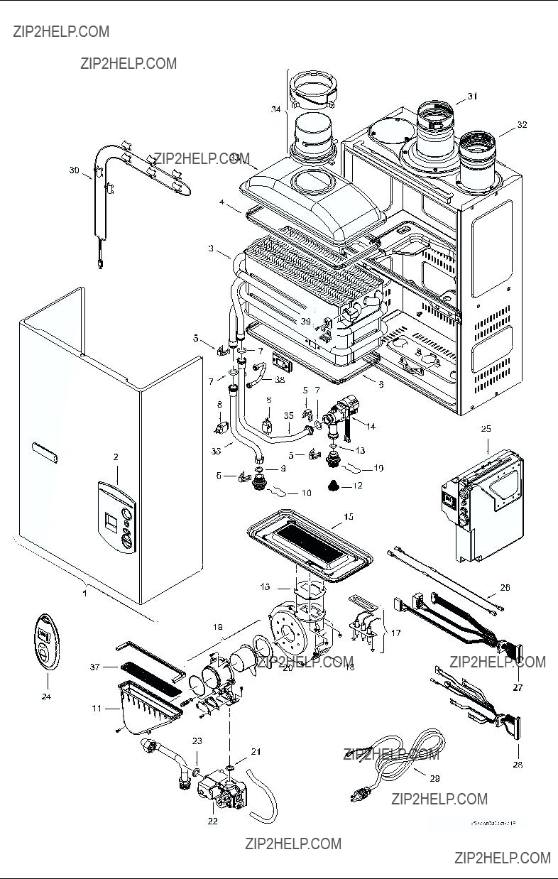
The heater is wired as shown in the wiring diagram (chapter 6, Fig. 36).

2.15 Operating instructions

BBefore proceeding with the operation of the heater make sure that the system is filled with water.

B Turn off power supply to heater.

B Open the cold water inlet supply to the heater fully.

BOpen a hot water faucet to permit the water to fill the heater and the piping and to eliminate the air trapped in the system.

BClose the hot water faucet after the water flows freely and all the air has escaped from the system. Turn on power supply to heater. The water heater is now ready to operate.

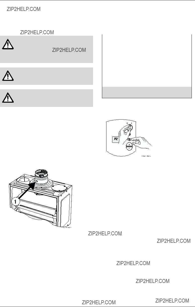
NOTE: A default temperature setting of

i122 F will appear on the display screen.

2.16For your safety read before operating your water heater

Warning: If you do not follow these instructions exactly, a fire or explosion may result causing property damage, personal injury or loss of life.

A.This appliance is equipped with electronic ignition for lighting the main burners. When turning the heater on, follow these instructions exactly.

B.Before operating the unit, set the On/Off switch to the On ( I ) position.

WHAT TO DO IF YOU SMELL GAS

B Do not try to light any appliance.

BDo not touch any electric switch; do not use any phone in your building.

BImmediately call your gas supplier from a neighbors phone. Follow the gas supplier???s instructions.

BIf you cannot reach your gas supplier, call the fire department.

C.Use only your hand to turn the on/off control switch. Never use tools. Follow these instructions exactly. If control switch is jammed, close the gas supply and call a qualified service technician. Attempted forceful repair may result in a fire or explosion.

D.Do not use this appliance if any part has been under water. Immediately call a qualified service technician to inspect the appliance and to replace any part of the control system and any gas control which has been under water.

2.17 Lighting and operating instructions

B 1. STOP! Read the previous safety information.

B2. The gas valve must be shut off by putting the ON/ OFF switch to position (0). Wait five (5) minutes to clear out any gas. If you smell gas, STOP! Follow ???B??? in the safety information above. If you do not smell gas, go to the next step.

B3. This appliance is equipped with electronic ignition for lighting the main burners. When turning the heater on, follow these instructions exactly.

B4. Set the ON/OFF switch to the (I) position. In this position, the water heater is ready to use.

B 5. Open a hot water tap.

B6. The burners will remain on until the hot water tap is turned off.

Appliance details

NOTE: on a first time initial instal-

ilation or after gas line work has been done, existence of air in the gas line will cause ignition delay when the hot water is turned on. This will result in an error (EA) on the units display screen. This is normal. When this occurs, leave the hot water running and wait 3-5 seconds, then reset the unit (Fig. 26, pos. 2). Wait for (EA) to disap- pear. The heater will begin to at- tempt ignition again, if the (EA) reappears then repeat this same process until all air has been bled from the gas line.

When the heater is in operation you will hear its power vent fan and burner operating. Upon turning off the hot water flow the power vent fan will continue to operate for up to 60 seconds to exhaust all flue gases. The power vents fan speed is variable depending on the rate of hot water used and the burner output.

TO TURN OFF GAS TO APPLIANCE

BTurn off the manual gas shut off on the supply line to the heater and set the ON/OFF switch to the OFF (0) position. Note: a manual gas shut off valve is not supplied with the heater.

Operation instructions

3Operation instructions

Fig. 26

1 On/Off switch

2 Reset button

3Program Key

4 Increasing temperature selector

5 Decreasing temperature selector

6LCD display

3.1Power

On

BTo start the appliance switch the button to position (I).

LCD display the default temperature - temperature factory setting 122??F (50??C).

Fig. 27

Off

B To shut down the appliance switch the button to position (0).

3.2Temperature selection

To select water temperature outlet:

B Press buttons and in order to reach requested temperature.

Fig. 28

If the outlet water temperature is set too high, the heater can produce temperatures that are too hot. A temperature balance shower valve can automatically mix in cold water to reduce such hot water temperature. In the event of any temperature instability with the use of a temperature balance shower valve, refer to shower valve manufacturer's instructions for internal adjustment setting. Adjustments should be made to the hottest setting in the shower valve. Additionally the temperature control of the heater can be lowered to produce a more comfortable hot water temperature.

Operation instructions

Setting the water temperature

The desired temperature of the hot water can be adjusted on the front control panel of the heater.

The GWH-635-ES has an electronically controlled gas valve that modulates the burner input in response to both varying hot water flow rates and/or changes in any incoming and outgoing water temperatures.

Hot Water Flow (GPM)

Hot Water Flow and Temperature with Various Inlet Temperature (gpm/Fahrenheit)

7.00

6.00

5.00

4.00

3.00

2.00

1.00

0.00

Hot Water Flow and Temperature with Various Inlet Temperature (lpm/Celsius)

Hot water temperature (??C)

Fig. 29 Flow/temperature charts

Operation instructions

3.3Use of remote control accessory

Fig. 30 Remote control

The wireless remote control accessory and the temperature selector buttons on the front of the water heater operate identically. Contact your distributor or CEC to order if the remote control accessory is preferred. Modification of the water heaters interior control unit (Fig. 29, component 12) is required when programming the remote control with this heater.

NOTE: up to 6 remote controls can be

iprogrammed for one single water heater, each with a range distance of 98 ft (30 m).

3.4Operation

BWhen a hot water tap is opened, main burner ignites and LCD displays indication .

Fig. 31

B LCD blinks until selected temperature is reached.

3.5Reset button

If the LCD shows the error symbol .

See the error code on LCD and consult ???Troubleshooting??? section.

Fig. 32

After following instructions indicated in ???Troubleshooting??? section

Bpress reset button in order to make the appliance ready-to-work.

Fig. 33 Reset button

If the problem persists, contact your installer.

3.6Program button

Program button can be used/programmed in the appliance and in the remote control.

Programming ???Program??? function

Programming actions are similar for both controls (appliance control pad and wireless remote control).

Fig. 34 ???Program??? key

BPress buttons and to select temperature to be memorized.

B Hold ???Program??? button for 3 seconds to save temperature.

When LCD stops blinking. Temperature is saved on ???Program???.

Using ???Program??? function

In order to select memorized temperature

B Press ???Program??? key.

LCD shows pre-memorized temperature, which is now the hot water selected temperature.

3.7Locked condition

This condition is only valid for appliances with more then 1 controller (appliances with remote control).

Fig. 35 Locked condition

Whenever LCD shows the temperature setting cannot be adjusted because the appliance is in use by a user which already selected a different temperature. Appliance will be automatically unlocked after closing hot water tap.

Maintenance and service

4Maintenance and service

Warning: Always turn off the electrical power supply, turn off the manual gas valve and turn off the manual water control valves whenever servicing.

The unit should be checked once a year by a gas technician. If repairs are needed, the repairs should be done by a gas technician

To remove front cover

BRemove plastic decals on front panel (Page 5, Fig. 4).

BLoosen the two Philips head screws located behind decals.

B Lift front cover panel upward and remove.

Systems and parts that should be checked at least once a year

Reference diagrams on pages 29 and 30.

???Venting system

???Burners -see page 29 for observation window

???Manual operation of the pressure relief valve to insure correct operation

???Periodic cleaning of the water filter screen, see Fig. 24, chapter 2.13.

???Flushing the heat exchanger with a descaling solution if mineral build up is evident. Scale build up will shorten the life of the water heater, descale heat exchanger thoroughly and repeat annually depending on mineral content of ground water.

5Troubleshooting

Introduction

The GWH-635-ES burner is activated by a water flow valve. Numerous water related problems can cause this water valve to malfunction such as: Insufficient water flow volume to activate the burners at its minimum flow requirement; Dirt in the water flow valve causing it to malfunction; Sediment build-up in faucet aerators, or shower heads; Uneven pressures between cold and hot (with single lever mix valves); and Plumbing crossovers. These water flow related problems can cause the heater to deliver less than its full output, or to fail to ignite or to shut down completely.

Problems stated below in upper case and in bold face should be investigated when there is a problem with the performance of the water heater but there is NO error code on the heater's LCD display or wireless remote control.

Any failures that result in a displayed error code are referenced on page 26. A Functional Scheme of the GWH-635-ES is detailed on page 28. If there is a problem with the installation, venting or operation of the

unit, the heater will communicate the source by these error codes.

BURNERS DO NOT IGNITE WHEN HOT WATER IS

TURNED ON

???Cold incoming water connection made to wrong side of heater

Make sure cold water inlet connection is plumbed to the right side of heater when facing unit

???Water flow rate at hot water tap is too low

A minimum of 0.8 gallon/minute (3 l/m) is required to activate the heater

???Cold water inlet filter screen is dirty

Remove water inlet filter screen and clean. The screen is located at the inlet connection to the water heater, disconnecting the main cold supply line at the heater is required. Check and clean faucet aerator screens too.

???Crossover in plumbing

The heater activates when there is sufficient water flow through its water valve, a minimum of 0.8 gallon/ minute (3 l/m) is required. If there is a crossover in the plumbing, the necessary hot water flow rate through the unit may not be reached, even though the flow at the hot water tap is sufficient. A plumbing crossover can be caused by a failed washer at a single lever faucet, incorrect plumbing or a faulty mixing valve in the piping. The crossover will create a back pressure on the water heater and prevent an adequate flow of water through it. To confirm there is no crossover in the plumbing, shut off the cold water supply feed to the water heater. Individually open each of the hot water taps. There should be no water flowing under a constant pressure. If there is a constant flow of water then the plumbing crossover must be corrected before the heater can operate properly.

WATER IS TOO HOT

???Temperature selection too high

Lower temperature adjustment on heater or wireless remote control accessory, see chapter 3.2.

WATER IS NOT HOT ENOUGH

???Temperature selection too low

Increase temperature adjustment on heater or wireless remote control accessory, see chapter 3.2

???Btu input is too low due to inadequate gas line sizing

See specifications in chapter 2.10 - 2.12. The GWH-635-ES requires adequate gas pressure to reach desired temperatures, to compensate for inadequate gas supply or lack of gas pressure the GWH-635-ES will effectively reach the selected output temperature by reducing the hot water flow rate. Its motorized water valve makes this adjustment

???Cold water is mixing with the hot water outlet (crossover)

Troubleshooting

Test by following 4th bullet under BURNERS DO

NOT IGNITE WHEN HOT WATER IS TURNED ON.

LOW WATER FLOW/PRESSURE

???Too many hot water applications are being used simultaneously or too much flow is being demanded

The GWH-635-ES will effectively support two 2.0- 2.5 gpm shower heads simultaneously or multiple sink applications. Greater draws will result in increased pressure drop and reduced flow at taps. See flow/temperature chart on page 22.

???Btu input is too low due to inadequate gas line sizing

See specifications in chapter 2.10 - 2.12. The GWH-635-ES requires adequate gas pressure to reach expected temperatures and flow rates, to compensate for inadequate gas supply or lack of gas pressure the GWH-635-ES will effectively reach the selected output temperature, but only by reducing the hot water flow rate. Its motorized water valve makes this adjustment. Proper gas pressure will need to be delivered before the motorized water valve will allow greater flow rates through it. Lowering the set temperature will also allow increased water flow rate through the motorized water valve. See flow/temperature chart on page 22.

???Cold water inlet filter screen is dirty

Remove water inlet filter screen and clean. The screen is located at the inlet connection to the water heater, disconnecting the main cold supply line at the heater is required. Check and clean faucet aerator screens too.

HOT WATER TEMPERATURE FLUCTUATES /

UNIT DEACTIVATED

???Unbalanced pressure in water lines

Any restriction caused by the water heater in the hot water system can result in uneven pressures between the cold and the hot. In such cases when mixing cold water at the tap (manually or automatically through a mix-type shower valve) the lower hot water pressure may be overpowered by the higher cold water pressure in the building and cause the hot water flow rate to fall below the minimum rate required. A pressure balance valve will help to resolve this symptom.

???Temperature balance valves

If the outlet water temperature is set too high, the heater can produce temperatures that are too hot. A temperature balance shower valve can automatically mix in cold water to reduce such hot water temperature. In the event of any temperature instability with the use of a temperature balance shower valve, refer to shower valve manufacturer's instructions for internal adjustment setting. Adjustments should be made to the hottest setting in the shower valve. Additionally the temperature

control of the heater can be lowered to produce a more comfortable hot water temperature.

???Inlet water pressure is erratic due to fluctuating supply water pressure

For installation on a private well system with the use of a pressure tank, the lowest pressure range setting recommended is 30-50 psi (2.07-3.45 bar). The use of a pressure reducing valve after the pressure tank is also an effective way to maintain a constant water pressure to the water heater. Watts brand 25AUB- ????? or N35B-????? pressure relief valves or equivalent are suggested.

NOISY BURNER / HEATER DURING OPERATION

???CO2 range is out of adjustment. The cover must be in place to confirm CO2 readings. Operating with the cover removed may cause a noisy or unstable burner.

See Chapter 9, CO2 adjustments can only be done by a certified gas technician with a calibrated CO2 analyzer.

Troubleshooting

Table 5

* By installer or service technician only.

Electrical diagram

6Electrical diagram

Fig. 36 Electrical scheme

1 Intlet water temperature sensor

2 Ionization sensor

3 Water flow sensor

4 Over heat protection

5 Temperature limiter

6Gas valve

7Fan

8 Water valve

9AC Plug

10Ignition electrode

11Display PCB

12ON/OFF switch

13Fuse T 1,25A

14Fuse T 3,15A

15Terminal block

16Ground post

17Outlet water temperature sensor

GWH-635-ES Functional scheme

7GWH-635-ES Functional scheme

Interior components diagram and parts list

8Interior components diagram and parts list

8.1Interior components

Fig. 38 Components

1Cover

2 On/Off switch

3 Reset button

4LCD display

5Program button

6 Temperature switches

7Flue gas collector

8Mixer

9Heat exchanger

10Observation window

11Inlet air duct

12Control unit

13Exhaust fan

14Water valve

15Gas valve

Fig. 39 Appliance overview

Interior components diagram and parts list

8.2Components diagram

Fig. 40 Components Diagram

Interior components diagram and parts list

8.3Parts list

Table 6

Special adjustment for measuring and adjusting CO2 levels

9Special adjustment for measuring and adjusting CO2 levels

The CO2 can only be adjusted by a certified gas technician with a calibrated CO2 analyzer.

Caution: Converting the gas type can only be done by a certified gas technician with a calibrated CO2 analyzer. Call CEC for conversion instructions.

Caution: Adjustments must only be carried out by authorized service personnel only.

Caution: The appliance should always be disconnected from the power supply before any maintenance is carried out.

9.1Adjusting the unit

Factory settings of this appliance are listed in table 7. Further adjustment is only needed if optimal CO2 level is required in order to assure the minimum possible CO2 emissions. In this case a CO2 analyzer is required.

9.1.1CO2 measuring port

B Loosen screw 1 (Fig. 41).

B Insert CO2 analyzer into measuring port (Fig. 41, pos. 1).

Fig. 41

1Measuring point

9.1.2Selecting adjustment mode

B ON/OFF switch in position OFF (0).

CO2 adjustment at minimum gas flow (P2) - See table 7.

* Final reading must be confirmed with the front cover on, CO2 levels increase when the cover is installed.

Table 7

B Press ???Program??? key and turn ON/OFF switch to position ON.

Fig. 42

LCD shows ???P2??? and the appliance is ready to be adjusted.

B Open hot water tap.

The appliance will run constantly at minimum power output and minimum water flow. This program step can also be used to measure minimum output and minimum water flow.

BTurn the screw in order to regulate the air-gas mixture

inside the ventilator until the CO2 level required is reached (Fig. 43, pos. 3).

CO2 adjustment at maximum gas flow (P1) - See table 7.

B Press , until ???P1??? appears.

B Open hot water tap.

The appliance will run constantly at maximum power output and maximum water flow. This program step can also be used to measure maximum output and maximum water flow.

BTurn the screw in order to regulate the air-gas mixture

inside the ventilator until the CO2 level required is reached (Fig. 43, pos. 3).

Special adjustment for measuring and adjusting CO2 levels

Caution: Faulty ignition or noisy operation may occur if CO2 levels are adjusted outside the indicated range.

Fig. 43 Adjusting

Leave ???Program??? mode

BTurn ON/OFF switch in position OFF and then ON again.

Protecting the environment

10 Protecting the environment

Packing

The packing box may be fully recycled as confirmed by the recycling symbol .

Components

Many parts in the heater can be fully recycled in the end of the product life. Contact your city authorities for information about the disposal of recyclable products.

Saving water resources:

BMake sure you close all the taps after any use. Avoid leaving the taps dripping. Repair any leaking tap.

BWhenever possible use taps with built-in water flow limiters. They will give you the same comfort level while saving water.

BDefine the temperature you want, in the appliance or with the remote control. This way you have the precise water flow needed (mixing cold water to regulate temperature will increase the water flow with consequent waste of water).

For increased safety shut off the appliance from the main water supply if your are staying away from home for a considerable time.

At below freezing temperatures, disconnect the plumbing connections to the heater and allow the heater to drain.

To prevent any freeze damage, introduce short bursts of compressed air (20-40 psi) through these connections to remove the residual water in the horizontal pipes and water valve.

Fifteen Year Limited Warranty

11 Fifteen Year Limited Warranty

General

BOSCH PRO water heaters are warranted by the Manufacturer (BOSCH) through Controlled Energy Corp. Controlled Energy Corp. (CEC) will furnish a replacement heat exchanger and will furnish a replacement of any other part which fails in normal use and service within the applicable periods specified below, in accordance with the terms of this warranty. The CEC replacement will be warranted for the unexpired portion of the original warranty. This warranty will be valid only for water heaters in possession of the original purchaser as recorded on the warranty card.

The Heat Exchanger

If the heat exchanger fails within fifteen (15) years after the original installation and operation, CEC will furnish a replacement heat exchanger. However, if the water heater is installed in other than a single family dwelling, this heat exchanger warranty is limited to two (2) years from date of original installation and operation.

Exceptions

This warranty will not apply:

???1. to defects or malfunctions resulting from failure to properly install, operate or maintain the unit in accordance with the printed instructions provided;

???2. to damage or abuse, accident, neglect or freezing and other acts of nature;

???3. to damage resulting from operation with either the flame sensor rod or overheat sensor removed;

???4. to failure of the heat exchanger resulting from the operation of the water heater in a corrosive atmosphere or at water temperatures exceeding the maximum rating, or if the water heater is not supplied with potable water;

???5. to defects or damage cause by any attachment or modification, including any energy-saving device.

All Other Parts

If any other part fails within three (3) years after original installation and operation, CEC will furnish a replacement part free of charge.

Shipping costs

In addition to supplying the replacement part(s), CEC will provide ground service delivery for these parts. Expedited or upgraded shipping will be charged to the customer.

Service Labor Costs

This warranty does not cover any labor costs associated with service, removal or re-installation of part(s). All such costs must be borne by the Purchaser. Additionally, this warranty does not cover any labor costs associated with service, removal or re-installation

of the original water heater or a replaced water heater. Certain service labor allowances are available to PHCC member contractors, dependent on prior authorization by CEC.

NOTE: the water heater must be free of

idamaging scale deposits and not subject to gas pressures greater than those shown on the rating plate, which must not be altered, defaced or removed.

How to Make a Claim

Any claim for warranty parts should be made to your local dealer, distributor or to CEC. If CEC, please contact the Technical Support Department:

Controlled Energy Corp.

340 Mad River Park

Waitsfield, VT 05673

Phone: 866-330-2730

www.protankless.com

In most cases, the dealer or distributor will be able to promptly honor your claim and subsequently notify CEC. However, all replacements are made subject to validation by CEC of in-warranty coverage. The damaged or defective item must be made available in exchange for the replacement.

Miscellaneous

No one is authorized to make any other warranties on behalf of CEC. It is expressly understood that the replacement warranty of CEC shall be in lieu of any and all other warranties, express or implied, including warranties of merchantability or fitness for a particular use or purpose, and further that CEC shall not be liable for any loss or damage directly or indirectly arising from the use of the hot water heater, or for any consequential damages arising from such use (including damages from water leakage). CEC???s sole liability with respect to any defect shall be for the replacement of the defective part(s). Some states do not allow such limitations and exclusions, so the above may not apply to you.

This warranty gives specific legal rights. You may also have other rights which vary from state to state.

Replacement Parts available from North American Distributor

CONTROLLED ENERGY CORP.

340 Mad River Park

Waitsfield, Vermont 05673

Phone 866-330-2730

Fax (802) 496-6924 www.protankless.com techsupport@protankless.com

Recycled paper

VULCANO Termodom??sticos S.A.

Estrada de Cacia

3801 - 856 Aveiro - PORTUGAL

?? 2004 Controlled Energy Corporation, Waitsfield, VT all rights reserved