Universal Monitor Mounts
en Mounting Guide
Universal Monitor Mounts
en Mounting Guide

Table of Contents
2Universal Monitor Mount Models 1
2.1
2.1.1Parts List 4
2.1.2Installing the
2.2
2.2.1Parts List 11
2.2.2Installing the
3.1

1Unpacking
This equipment should be unpacked and handled with care. If an item appears to have been damaged in shipment, notify the shipper. Verify that all parts shown in the Parts List are included. If any items are missing, notify your Bosch Security Systems Sales or Customer Service Representative.
The original packing carton is the safest container in which to transport the unit. Save it for possible future use.
2Universal Monitor Mount Models
The Bosch series of Universal Monitor Mounts (UMM) are designed to mount any
2.1
The
Figure 2.1

Table 2.1

2.1.1 Parts List
The following table lists the components for the mount:
1 VESA mounting plate (A) and wall bracket (B)
(see Figure 3.1 on page 16 for a dimensional drawing)
2 1/4 x 2.0 in. Wedge anchors (C)
(see Figure 3.3 on page 18 for a dimensional drawing)
2 1/2 x 2.0 in. Wood screws (D)
(see Figure 3.3 on page 18 for a dimensional drawing)

4M4 x 10 mm screws (E)
(see Figure 3.4 on page 19 for a dimensional drawing)
1 Level (F)
2.1.2 Installing the
To install the wall mount:
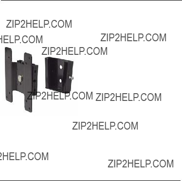
1.Disassemble the mounting plate (A) from the wall bracket by removing the lock screw from the wall bracket (B). Retain the lock screw for later use.
2.Determine the location on the wall that you will attach the wall bracket. Use Table 2.1, on page 3, for recommended mounting surfaces.
3.Place the wall bracket (B) against the wall, as illustrated below, and use the level (F) to ensure that the bracket is level.
Figure 2.2 Wall bracket with level
4.Use the wall bracket as a template to mark the mounting holes on the wall.
5.Attach the wall bracket (B) to the wall.
a.Use the two (2) wedge anchors (C) to attach the wall bracket to concrete or to a cinder block.
b.Use the two (2) wood screws (D) to attach the wall bracket to a stud behind wallboard or to

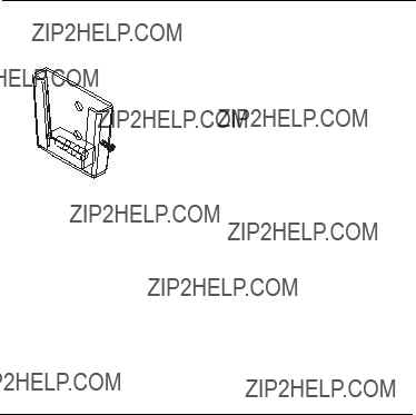
6.Attach the VESA mounting plate (A) to the back of the
100
Figure 2.3 Attach the VESA monitor plate
7.Carefully slide the mounting plate into the slots of the wall bracket.
Figure 2.4 Attach monitor plate to wall bracket
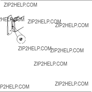
8.Tighten the lock screw, located on the right side of the wall bracket, using a Phillips head screw driver.
Figure 2.5 Lock screw on the wall bracket
2.2
The
Figure 2.6


2.2.1Parts List
The following table lists the components for the mount:
1 VESA mounting plate (A) and wall bracket (B) (see Figure 3.2 on page 17 for a dimensional drawing)
2 1/4 x 2.0 in. Wedge anchors (C)
(see Figure 3.3 on page 18 for a dimensional drawing)
2 1/2 x 2.0 in. Wood screws (D)
(see Figure 3.3 on page 18 for a dimensional drawing)

4M4 x 10 mm screws (E)
(see Figure 3.4 on page 19 for a dimensional drawing)
1 Level (F)
1 Wrench (G)
2.2.2 Installing the
To install the wall mount:
1.Disassemble the VESA mounting plate (A) from the wall bracket (B) by removing the thumb screw on the wall bracket. Retain the thumb screw for later use.
2.Determine the location on the wall that you will attach the wall bracket (B). Use Table 2.2, on page 10, for recommended mounting surfaces.

3.Place the wall bracket (B) against the wall, as illustrated below, and use the level (F) to ensure that the bracket is level.
Figure 2.7 Wall bracket with level
4.Use the wall bracket as a template to mark the mounting holes on the wall.
5.Attach the wall bracket (B) to the wall.
a.Use the two (2) wedge anchors (C) to attach the wall bracket to concrete.
b.Use the two (2) wood screws (D) to attach the wall bracket to a stud behind wallboard or behind
6.Align the back of the monitor to the correct hole pattern on the VESA mounting plate.

7.Attach the VESA mounting plate (A) to the back of the
Figure 2.8 Attach the VESA mounting plate
8.Carefully slide the mounting plate into the slots of the wall bracket.
Figure 2.9 Attach monitor plate to wall bracket

9.Tighten the thumb screw, located on the right side of the wall bracket.
Figure 2.10 Thumb screw on the wall bracket
10.Tilt and swivel the mount to achieve the optimum viewing angle.
11.Use the wrench (G) to tighten the nut, located on the left side of the mount.
Figure 2.11 Tighten nut to lock mount position

3Dimensional Drawings
3.1
75
 30
30
100 mm
65  30
30
79
5 . 8
Figure 3.1

3.2
75
129
100 mm
Figure 3.2
140
 140
140
5 . 8
79

3.3UMM Series Component Dimensions
??12.5 mm
Figure 3.3 Wedge Anchor and Wood Screw Dimensions
??7.5??0.15 mm
mm 2.0??5.12
mm 5.0??8
Figure 3.4
??3.95??0.05 mm
mm 2.0??10
??3.8??0.05 mm
7.0 x mm 4
M4x10 mm Screw Dimensions


Bosch Security Systems, Inc.
850 Greenfield Road
Lancaster, PA 17601
USA
Telephone +1 888
www.boschsecuritysystems.us
?? Bosch Security Systems, Inc. 2008; F.01U.115.026 | 3.0 | 2008.12