Fire Alarm Control Panels
en Installation and Operation Manual
Fire Alarm Control Panels
en Installation and Operation Manual

Fire Alarm Control PanelsTable of Contents | en 3
Table of contents

4 en | Table of ContentsFire Alarm Control Panels

Fire Alarm Control PanelsTable of Contents | en 5

6 en | NoticesFire Alarm Control Panels
equivalence number (REN) for this equipment. You must, upon request, provide this information to your local telephone company.
The REN is useful to determine the quantity of devices that can be connected to your telephone line and still have all of those devices ring when your telephone number is called. In most, but not all areas, the sum of the RENs of all devices connected to one line should not exceed five. To ascertain the number of devices that you can connect to your line, contact your local telephone company to determine the maximum REN for your local calling area.
This equipment can not be used on coin service provided by the telephone company. Do not connect this control panel to party lines. If this equipment causes harm to the telephone network, the telephone company might discontinue your service temporarily. If possible, they will notify you in advance. But if advance notice isn???t practical, you will be notified as soon as possible.
You will be informed of your right to file a complaint with the FCC. The telephone company might make changes in its facilities, equipment, operations, or procedures that could affect the proper functioning of your equipment. If they do, you will be notified in advance to give you an opportunity to maintain uninterrupted telephone service.
If you experience trouble with this equipment, contact the manufacturer for information on obtaining service or repairs.
The telephone company might ask that you disconnect this equipment from the network until the problem is corrected or until you are sure that the equipment is not malfunctioning. The manufacturer, not the user, must make the repairs to this equipment. To guard against accidental disconnection, there is ample room to mount the telco jack inside of the control panel cabinet.
The operation of this control panel might also be affected if events such as accidents or acts of God cause an interruption in telephone service.

Fire Alarm Control PanelsNotices | en 7
1.3Industry Canada Notice
The Industry Canada label identifies certified equipment. This certification means that the equipment meets certain telecommunications network protective, operational, and safety requirements. Industry Canada does not guarantee the equipment will operate to the user???s satisfaction.
Before installing this equipment, users should ensure that it is permissible to be connected to the facilities of the local telecommunications company. The equipment must also be installed using an acceptable method of connection. The customer should be aware that compliance with the above conditions might not prevent degradation of service in some situations. Repairs to certified equipment should be made by an authorized Canadian maintenance facility designated by the supplier. Any repairs or alterations made by the user to this equipment, or equipment malfunctions, might give the telecommunications company cause to request the user to disconnect the equipment.
Users should ensure for their own protection that the electrical ground connections of the power utility, telephone lines, and internal metallic water pipe system, if present, are connected together. Users should not attempt to make such connections themselves, but should contact the appropriate electric inspection authority, or electrician.
1.4Trademarks
All hardware and software product names used in this document are likely to be registered trademarks and must be treated accordingly.
Microsoft, Windows, and Windows NT are either registered trademarks or trademarks of Microsoft Corporation in the United States and/or other countries.
CYCOLOY is a registered trademark of Sabic Plastic.
POLYLAC is a registered trademark of CHI MEI Industrial Corporation, LTD.
CleanMe is a trademark of GE Interlogix, Inc. in the United States and/or other countries.

8 en | OverviewFire Alarm Control Panels
Figure 2.1:

Fire Alarm Control PanelsOverview | en 9
detectors. The system has an optional alarm verification feature.
All
2.2.2Off-board addressable points (with D7039 Multiplex Expansion Module)
The D7039 Multiplex Expansion Module adds:
??? Two Class B, Style 4 or one Class A, Style 6 Signaling Line Circuits (SLCs)

???Each point is individually supervised for proper connection to the common bus (when over ten points are troubled, up to ten troubles are shown per bus and the balance of the troubles is indicated by a common bus failure message).
???Response time can be set to fast, or programmed from 1 to 89 seconds.
???Input points on the SLCs are implemented with a D7042 Eight Input Remote Module.
Fire Alarm Control PanelsOverview | en 11
For the LED display for Zones 49 to 64, see the following table.
Table 2.3: LED display for Zones 49 to 64
See also

12 en | OverviewFire Alarm Control Panels

Figure 2.2: Supplemental Reporting
2.2.8Users
The system allows up to 16 individual users, or up to 100 users when the D7039 is installed. A personal identification number (PIN, the
2.2.9Lightning protection

14 en | OverviewFire Alarm Control Panels

2.2.11Required batteries for existing load
Use the following procedure to determine the battery requirements for your system:
???Estimate the size of the battery required to support the standby load using the following table:
Table 2.6: Standby load battery size (Ah)
???Estimate the size of the battery required to support the alarm load using the following table:
Table 2.7: Alarm load battery size (Ah)
???Add the results together for the total battery size.

???Select the next larger standard battery for the system.
If the results show a requirement for a battery over 40 Ah, reduce the existing load or add an external regulated fire protective signaling power supply.

18 en | OverviewFire Alarm Control Panels

The FPD???7024 comes with:
???One
???One enclosure with transformer
???One hardware pack containing the hardware necessary for installing the control panel in the enclosure
???One enclosure lock, washer, and keys
???Six

20 en | Fire SafetyFire Alarm Control Panels
For residential smoke detector locations, see the following figure:
A fire warning can be wasted unless the personnel planned in advance for a rapid and safe exit from the building.
Draw a floor plan of the entire building showing two exits from each sleeping area and two from the building. Since stairwells and hallways can be blocked during a fire, provide exits from sleeping area windows. Make copies of the plan and practice it with all personnel.
Arrange a meeting place outside and away from the building. Once out of the building, all occupants should immediately go to the
Provide a barricade between personnel and fire, smoke, and toxic gases (such as closing all sleeping area doors before retiring).
Instruct children on opening their bedroom windows and exiting safely from the building. If exiting is not possible, teach them to stay at the open window and shout for help until it arrives.
If a fire alarm occurs after retiring, wake the children by shouting to them from behind your closed door. Tell them to keep their bedroom doors closed.
If the top of your bedroom door is uncomfortably hot, do not open it. There is most likely fire, intolerable heat, or smoke on the other side. Shout to all family members to keep their bedroom doors closed and to exit the building by alternate routes.
If the top of the door is not uncomfortably hot, brace the bottom of the door with your foot, and the top with one hand, then open the door about one inch. Be prepared to slam the door shut if there is any pressure against the door or if any hot air rushes in.
If there is no evidence of excessive heat or pressure, leave the room and close the door behind you. Shout appropriate instructions to all family members and immediately leave the building by the planned routes. If heavy smoke is present, drop to your hands and knees, or crawl to remain below the smoke level.

22 en | InstallationFire Alarm Control Panels
When used in UL Listed installations, the control panel must conform to certain programming requirements. For a list of the required program entries specific UL Listed installations, see the Programming features for UL864 table, 49.
Commercial Fire Alarm (Central Station [DACT] and Local)
Required Accessories
??? At least one Bosch Security Systems, Inc. Model F220???P Smoke Detector with an F220 Family Base; or another UL Listed compatible smoke detector.
??? At least one Horn Strobe or Bell (provides 85 dB for UL985 and NFPA 72 requirements; other UL Listed compatible devices listed for regulated 24 V can be used) is required for this application and must be installed inside the protected area.
???
??? All points must be used with the resistor provided.
Report Programming
??? Program
??? Program trouble reports.
??? Set AC Failure Report Delay for a delay of 1 hour to 3 hours.
??? Set automatic test report frequency to occur at least every 24 hours.

Timer Programming
???Program Auto Silence Time for not less than five minutes, or to ???0??? to disable
operation.
Point Programming
???For fire points: open = trouble, latching.
Alarm Output Programming
???Program notification appliance circuits to activate from the appropriate input points.
Communications Programming
???If used for Central Station Service, select a communication format compatible with the central station. Enable monitoring of both phone lines.
UL Listed Accessory Devices
D132B
The D132B is a
See also the D132B Installation Guide for detailed installation instructions for the D132B module. One of the installation options shown in the D132B Installation Guide is also shown in the following figure:

Figure 4.1: Wiring the D132B smoke power reversing module
D185 Reverse Polarity Module
The D185 Reverse Polarity Module is a UL Listed module that connects the control panel with either a single set or a pair of leased telephone company (TELCO) lines in NFPA 72 remote station applications. It relays system alarm status information from the control panel to a monitoring station. The D185 operates with either 12 VDC or 24 VDC supply.
For typical wiring of the D185 module, see the following figure:

Figure 4.2: Wiring the D185
The module can signal alarm, trouble, and supervisory conditions. The Wiring the D185 figure, 24 shows the module being used to signal alarm and trouble conditions only. With a third relay (available from the
In the example in the Wiring the D185 figure, Relay 1 must be programmed to operate on Alarm (Zone 63) and Relay 2 must be programmed to operate on Trouble (Zone 62). Program Input 4 to operate as a Supervisory point. Any alarm causes the voltage to the monitoring station to be interrupted. Placing the D185 in test mode causes a SUPERVISORY TROUBLE. See also the D185 Installation Manual.
5.Install and tighten the remaining two screws in the bottom mounting holes.
6.Knock out the desired wire entrances on the enclosure.
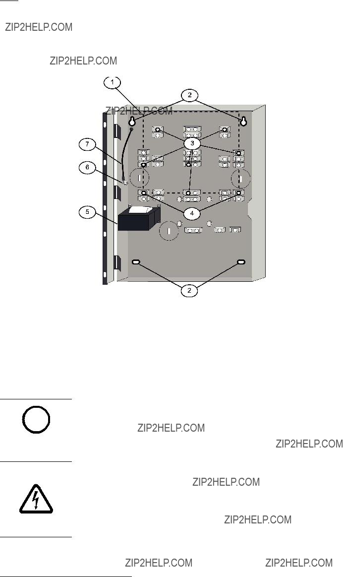
For mounting hole locations, see the following figure:
Figure 4.3: Enclosure iInstallation
Danger!
The control circuit board in the
To avoid damage to sensitive components, touch ground before handling the control board. This discharges any static electricity in your body. For example, run the ground wire to the en- closure before handling the control circuit board. Continue touching the enclosure while in- stalling the control board.

Warning!
Before the circuit board is installed, connect the supplied ground wires between the door and
!the enclosure and from the transformer to the enclosure using the supplied nuts. Both grounds connect to the stud in the enclosure to the left of the circuit board.
For installation illustrations, see the figures for Enclosue installation, 26 and for Standoff and support post installation, 27.
1.Insert the three support posts in the enclosure???s retainer holes.
2.Press the 1/8 in. nylon standoffs (P/N: F01U034705) into the retainer holes.
3.Slide the top of the control panel onto the retainer tabs (the slots under the top of the frame). When the control panel is in the retainer tabs, it rests on the posts.
4.Secure the bottom of the circuit board by inserting and tightening the screws at the two bottom corners through the support posts and the retainer holes.
For installing standoffs and support posts, see the following figure:
Two expansion options connect directly to the control panel, and are automatically detected and supervised when the control panel is powered:
???
???D7039 Multiplex Expansion Module
When the control panel is powered after installing one of these options, the control panel displays one of the following windows:
4Z EXP DETECTED
PRESS BACK KEY
MUX DETECTED
PRESS BACK KEY
Press the [*/BACK] key to confirm the installation of the device and automatically set it up for supervision.

If the [*/BACK] key is not pressed during the
Warning!
Expansion devices such as point expanders and multiplex expanders are disabled if they are
!removed from the control panel configuration after installation. You cannot disable supervi- sion of these devices when they are installed.
For additional information, see the installation instructions for the specific expanders.
Notice!
EEPROM fault at first installation
When the D7039 Multiplex Expansion Module is first installed, the system displays an EE- i PROM fault. Execute the default procedure to synchronize the EEPROM on the expansion
module to the EEPROM in the control panel. Remove power to the control panel, then reapply power and
Notice!
Loss of programming
i Replacing a D7039 Multiplex Expansion Module causes the loss of programming of expansion points and PINs. Reprogram all multiplex point and PINs if you replace the D7039.
When the D7039 is first installed, or anytime the control panel is powered with a D7039 that has no points programmed, the system automatically starts the multiplex
AUTO PROGRAM?
_______:YES(1) NO(0)
Pressing the [1] key starts
For detailed instructions on the

Fire Alarm Control PanelsConnection | en 29
Danger!
Incorrect connections may result in damage to the unit and personal injury.
Warning!
!Before servicing this equipment, remove all power including the transformer, battery and phone lines.
Figure 5.1: Typical
2 Class B, Style B
Figure 5.2: Typical
Notice!
All wiring except battery terminal and primary AC power is
movement.
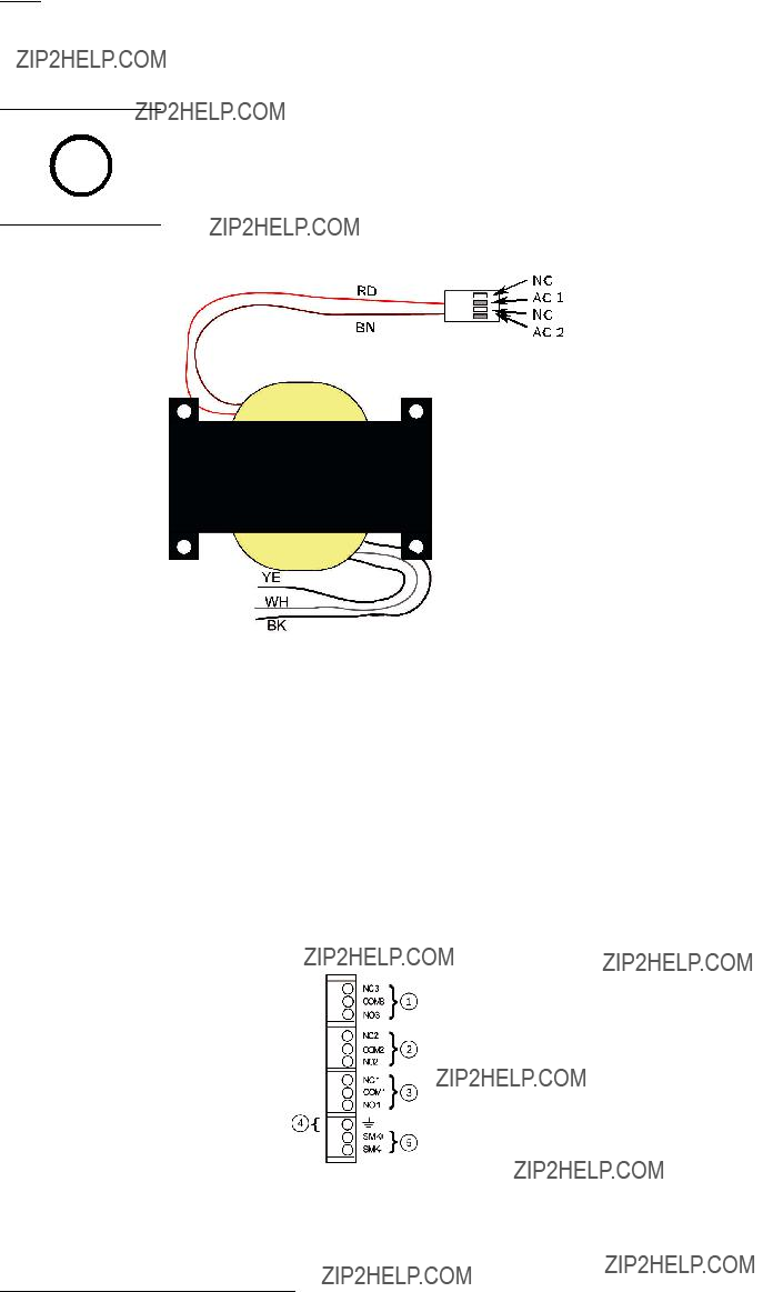
Figure 5.3: Transformer
Figure 5.4: Input Points
Fire Alarm Control PanelsConnection | en 31
Input Points
(supervised) Points are intended for connection of
Figure 5.5: Telephone lines 1 and 2

DX4020,
B420 MODELS,
Figure 5.6: Keypad Connection (supervised, Class B, Style 4, 500 mA maximum)

Danger!
Explosion and burn hazard!
Do not short terminals!
5.2Power supply connection
Use wire nuts to connect the primary side of the transformer in one of the following ways:
??? black and white wires to an unswitched 120 V, 60 Hz, or
??? yellow and white wires to an unswitched 240 V, 50 Hz circuit.
Danger!
Shock Risk!
Do to risk of shock and/or damage to the transformer a wire mut must be in place over the unused black or yellow wire.
Connect the earth ground to the threaded ground stud on the left side of the enclosure.

Use 18 AWG (1.2 mm) or larger wire to connect option bus devices to the FACP. The total length of wire connected to the option bus terminals must not exceed 4 000 ft (1 219 m), regardless of the wire gauge wire used.

Add together the alarm existing current draw by all the devices on the wiring run to determine the maximum allowed distance between the option bus terminals on the control panel and the last device on the wire run (the device farthest from the control panel).
To determine the maximum allowed length for the run, add up the total alarm load for option bus devices on the wire run. For example, if the total load of option bus devices on a particular run is 400 mA, the maximum length of the run can be up to 500 ft (152 m). No more than 4 000 ft (1 219 m) of wire can be connected to the option bus terminals, even if the individual lengths of the runs are all within limit.
For the allowed lengths for18 AWG (1.2 mm) wire, see the following figure:
Figure 5.9: 18 AWG cable length for existing current draw
Notice!
The graph is for 18 AWG cable!
i For16 AWG (1.5 mm) wire, cable lengths can be 1.5 times longer. For14 AWG (1.8 mm) wire, cable lengths can be 2.5 times longer. The 4 000 ft (1 219 m) maximum length of connected wire still applies.

36 en | System OperationFire Alarm Control Panels
supervisory (XXX), where XXX indicates the number of supervisory conditions. The bottom line indicates more instructions. The built???in sounder beeps. Outputs programmed to activate with the existing condition(s) then activate.

6.1.6Trouble
When a trouble condition occurs (such as cut wiring for a point or AC power fails), the sounder beeps every 10 seconds. The Trouble LED lights and the LCD shows the trouble condition. When you back out of the detailed screen when the [4/<] key is pressed the group is entered and shows TROUBLE (XXX). The system can diagnose and show a variety of trouble conditions, including those affecting the input points, NAC circuits, power, battery, system grounding, and internal operations of the fire control panel. Notify your installing company immediately if the system trouble message appears.
Press the [Acknowledge] key to silence the system trouble beep.
Danger!
Fire Alarm!
During a fire alarm, exit from the premises immediately. Do not enter the premises unless ac- companied by the appropriate emergency services' personnel, or until they have given the OK to enter.
DANGER!
When it is determined that there is no fire, you can silence the horns or bells to allow more investigation of the devices that initiated the alarm, or you can reset the system to return it to normal operation.
Notice!
Before resetting fire alarms
Before using the [Reset] key, determine which smoke detector sounded the alarm so that the i monitoring company can check that the system is operating correctly. If the control panel is
being used as an addressable control panel, use the [History] key to determine which address is in alarm.
NOTICE!
If the system is configured to allow alarm silencing, the [Silence] key turns off the horns or bells, but does not reset the alarm status and does not return the activated input to normal service. Detectors that were activated stay in alarm and can be checked (usually by observing an LED on the device) to see which detector caused the alarm. When the detectors causing the alarm are identified, reset the system to return it to normal service.
The [Reset] key clears the system alarm status, and briefly turns off power to the detectors to reset them. This command is required after any fire alarm affecting a point programmed for latching operation (which is the normal configuration). This operation is also required to reset Class A, Style 6 multiplex (SLC) wiring fault troubles.
The software automatically supervises the system software for proper operation. If the system fails, a CPU FAULT message appears, and the nature of the failure can be optionally recorded in the history buffer. To enable history buffer recording for CPU faults, program Output Zone D of onboard Relay 2 to Zone 51 (unused). The history buffer message, if enabled, shows CPUFLTxxx, where xxx is an error code. If the display shows CPU FAULT, contact Bosch Security Systems, Inc. Technical Support and report the history buffer code along with a description of the operations that caused the fault. Unusual conditions during programming and debugging operations can result in a CPUFLT message in the history buffer. If, this occurs when the control panel is in service, report it to Technical Service.

38 en | System OperationFire Alarm Control Panels
disabled, the system shows this condition on the LCD and on the system trouble LED. The Disable All Inputs operation takes several seconds to perform, during which time the system display remains fixed.

Fire Alarm Control PanelsSystem Operation | en 39
The HISTORY option is a chronological list of system events that occurred. Press the [History] key to HISTORY select from the Main Menu (SYSTEM NORMAL display).
On an
On an
After you press the [History] key, the most recent system event appears on the top line of the LCD with the time and date below it.
Example: (Assume you pressed the [History] key at the Main Menu):
While the first event shows, the bottom line toggles every four seconds between the time and date that the event occurred.
To return to a previous screen in the history buffer, press [2/???].To scroll to the next event record, press [8/???].
For abbreviations used in history events, see the following table:
Table 6.2: History event abbreviations

40 en | System OperationFire Alarm Control Panels
line by
Figure 6.1:

42 en | System OperationFire Alarm Control Panels
The
For operation, see

Figure 6.2:
flashes. When the communication succeeds, a long keypad beep sounds, the Power LED returns to normal, and the display returns to normal.

Notice!
This test is available only if your system sends alarms and system information to a monitoring i service, and was programmed by the security installing company to permit communicator
tests.
NOTICE!
Warning!
Reset upon termination of test
Terminating the communicator test function (with the [*/Back] key) resets the communicator
!and discards all unsent reports. When an
Address 128 on Bus 1, or below Address 129 on Bus 2. If you know that a device is connected to the system but cannot find it, ensure that it is connected to the correct bus: 9 to 128 for Bus 1, 129 to 255 for Bus 2.
4. Show Missing: Lists devices programmed into the system but not present on the bus are listed. Unless a device was programmed into the system (such as using MUX EDIT), it is not considered missing.

5.Show Status: After you select a device and press [#/Enter], this test shows detailed status information for the selected device. Eight conditions (not all status conditions apply to or are supported by all devices) are shown. See the display shown below (which updates automatically every five seconds). For this option, you can view the status of any MUX device regardless of which bus you selected to test when test mode was entered.
???XxLxRxDxMxTxFxAx
x is either 0 or 1 depending on whether the condition is false or true (0=false and 1=true). The letters indicate the condition:
???X: Reserved for future use.
???L: Commanded relay state - this is how the output relay should be set. R: Actual relay state - this is how the output relay is actually set.
???D: Detector dirty - the detector is excessively sensitive.
???M: Missing device - the device cannot be found on the loop. Unless a device was programmed into the system (such as using MUX EDIT), it is not considered missing.
???T: Tamper ??? the detector???s case was opened.
???F: Loop fault - the loop from a contact input device is open, or the device is faulted. A: Loop alarm - the point is in alarm.
Pressing [*/Back] ends the display for any of these modes.
Examples: X0L0R0D0M0T0F0A0 (relay off, not dirty, not missing, no tamper, no fault and no alarm).
6.5Point/Zone Mapping
The control panel supports a flexible system to map input points to output points. The system defaults so that all NAC outputs are activated by a fire alarm. By programming output zones, you can create almost any output activation scheme, such as ???floor above and floor below??? activation or conditional elevator recall.
Input points: Smoke detectors, pull stations, and so on.
Zone: A group of input points (Zones 1 to 50 are configurable, 52 to 63 are activated automatically).
Output points: NACs (notification appliance circuits) such as bells, strobes, and relays. Inputs activate zones, and zones activate outputs.
Zones 1 to 50 are available for the installer to program. Each input can activate one zone; however, any number of inputs can be mapped to the same zone.
Zones above 50 are automatically activated by inputs. For example, any input that is configured as a waterflow type activates Zone 61 when it is alarmed. Any output driven by Zone 61 activates when any waterflow type point is alarmed.
Up to 64 zones can be assigned. The installer can assign Zones 1 to 50. Zones 51 to 63 are
For how inputs control zones and zones control outputs, see the following figure:

Figure 6.3: Mapping inputs, zones, and outputs
For

Zone Condition
61General Waterflow
62General Trouble. Active while any system trouble is present, not active in test and programming modes.
63General Alarm, Waterflow

Warning!
Event sorting can hide unrestored points
!Priority sorting on events sent to a monitoring station can cause the message sequence to im- ply that a point is restored when it is not.
The communicator can store 32 events while waiting for the monitoring station to accept the events. If more than 32 reportable events occur before the monitoring station accepts events, some event information is lost and a Data Lost report is sent to the central station.
The FPD???7024???s communicator is equipped with a line seizure relay to prevent interference with outgoing event reports. In a system where the fire communicator shares the phone line with other equipment on the premises, the phone line might be unavailable to the other equipment for up to 15 min has a fault with the central station acceptance of the event data. Phone lines for fire control panels must not be shared with other equipment.

7Programming
Danger!
Untested systems!
After any programming change, and especially after remote programming changes, completely check the operation of the control panel. Hazards to life and property can result if the system is not tested to detect possible improper programming.
DANGER!
Warning!
Improper system operation!
When programming the system, enter only valid types of information within the ranges speci-
!fied in the programming table. Incorrect programming results in improper system operation. When using

50 en | ProgrammingFire Alarm Control Panels
Each of the points in the system can be programmed with its own characteristics. Point functions simplify the programming of points by allowing you to define a common set of characteristics for similar points, and assigning those characteristics to selected points as a point function. There are 16 point functions, each of which has programmable features for configuration (fire, waterflow, and so on), local only operation, silencing, and loop response. Each point is assigned to use the characteristics of one point function, and then is individually programmed for additional characteristics: response to an open circuit, enabled status, output zone, verification, latching and point description.
Before programming the control panel, determine the types of functions that are needed, and then map the various input points to the functions. For example, you might determine that you have the following functions:
1 = Pull Station
2 = Smoke Detector
3 = Reset Keyswitch
4 = Silence Keyswitch
5 = Supervisory Input
6 = Local Test
7 = Waterflow Sensor
For the characteristics that correlate with each function, see the following table. For default point function information, see Appendix D.
Fire Alarm Control PanelsProgramming | en 51
When programming the point descriptions, the numeric keys are used to enter alphanumeric information similar to the way telephone keys are used to process information over the phone lines each key represents four or more letters or symbols. For alphanumeric point programming, see the following table:

52 en | ProgrammingFire Alarm Control Panels
Returns to the programming menu without entering changes.
B*ACK
Moves the cursor one space to the right.
SILENCE
Moves the cursor one space to the left.
DISABLE
1 Press [1] nine times to reach this value.
2 Press the listed key four times to reach this value.
Table 7.3: Programming points using alphanumics

4/2
When 4/2 Format is used, reports generated by points consist of an event type (first digit) and a point number (second digit). Digits can be programmed for the following events: fire alarm, fire restoral, waterflow alarm, supervisory alarm, point trouble, trouble restore, point disable, disable restoral, and monitor alarm. The same event type (first digit) is sent for any point. The point number is the second digit. Each point can be programmed to a different digit. This programming is done under
7- PROG FORMATS, 1- 4/2 POINT RPT.
Additionally, 18 system events can each be programmed with a unique
Phone 1 Trouble, and Phone 2 Restoral. This programming is done under
7- PROG FORMATS, 2- 4/2 RPT CODS.
The 4/2 (and 3/1) format cannot report full point data for each point. Points 1 to 10 have unique reporting codes. The codes repeat every ten points. For example, Point 31 has the same point report as Points 11 and 21.

BFSK
Similar to the programming of system events for 4/2 formats, five system events can be programmed for two unique digits each when the BFSK format is used. This programming is done under
7- PROG FORMATS, 3- BFSK RPT CODS.
The BFSK format supports only a
SIA
The SIA reports are fixed, and do not require programming.
Contact ID
The Contact ID reports are fixed and do not require programming.
3/1
The 3/1 reporting codes are determined by the programming of the 4/2 codes. Send only Digit 1 (left digit of the
Modem IIIa2
The Modem IIIa2 reports are fixed and do not require programming.

Fire Alarm Control PanelsProgramming | en 55
Figure 7.2: Program Menu
For factory defaults, see Appendix D.

Figure 7.3: Program Menu - continued
For factory defaults, see Appendix D.
7.6Shortcuts
You can use shortcuts to reduce repetition and provide speedy instructions for programming the control panel.
The first level in the system is the Main Menu. For all system programming, <PROG/0> is your Main Menu choice. Therefore, the first number in the shortcut is ???0???.

LEVEL 1
(MAIN MENU)
5
PROG/0
4
The second level in your system provides eight options: PROG TIME, SECURITY,
PROG SYSTEM, PROG INPUTS, PROG OUTPUTS, PROG ACCOUNTS, PROG FORMATS, and HISTORY DEFAULTS. When the D7039 MUX Expander is installed, a ninth option appears: PROGRAM MUX. The second number in the shortcut enters the Level 2 option and allows access to Level 3.
Level 3 provides the third set of options that branch from Level 2. The third number in the shortcut represents the option chosen in Level 3.
For an example of the shortcut to TEST FREQ and TEST TIME, see the following figure. The sample of the Program Menu Tree shows that to get to TEST TIME and TEST FREQ, you must go to PROG/0 in Level 1, PROG TIME in Level 2, and AUTO TEST in Level 3. The shortcut is simply a list of the keys you press to get to the fourth level option. Once you enter the shortcut, follow the procedural description that appears on the screen of the specific function you are programming.
2
1 3
SHORTCUT = 012
1- SYSTEM
1- PROG TIME
1- TEST TIME
2- AUTO TEST
2- TEST FREQNCY
The system operates during remote programming so that new alarms end the remote programming session and report normally. Using the keypads to perform other functions during remote programming (such as tests and disables) can cause remote programming to disconnect or other unexpected operations. Avoid downloading programming changes that cause alarms, because the session disconnects as soon as the alarm occurs, before the session completes. To indicate that the system is in a special operating mode with user input

inhibited (but alarm monitoring continuing), the system indicates SYSTEM TROUBLE,
RMT PRG ACTIVE during remote programming. Sounders do not activate during this mode, but other outputs programmed for Zone 62, general system trouble, do activate.
Trouble conditions that occur during a remote programming session are not annunciated at the control panel until the remote programming session ends. These conditions are available in the remote programmer diagnostic displays during the session. Alarm conditions terminate remote programming and are shown immediately.
When remote programming is disabled, you can still connect to the control panel for diagnostics and view the existing programming (except PIN numbers). To actually change programming, enable remote programming.
To enable remote programming, refer to the following programming items:
???
???
???
???
???
???
An access code with maximum authority (1) is needed to begin remote programming from the panel.

Fire Alarm Control PanelsControl Panel Programming | en 59
Test Time
Shortcut:
Use this feature to program the time of day at which automatic tests occur. This feature uses a 24???hour clock (for example, 11:00 p.m. = 2300).
The following window appears:

AUTOMATIC TEST
Press [1] to select Test Time. The following window appears:
AUTO TEST TIMEHHMM: _______
Enter the time followed by the [#/Enter] key.
Test Frequency
Shortcut:
This feature allows you to program how often the automatic test reports are sent. The first test is sent when the programmed test time matches the system time. Subsequent reports are sent according to the selected interval.
The following window appears:
AUTOMATIC TEST
Press [2] to select Test Frequency.
The following window appears:
AUTO FRQNCY ( )
* For acceptable programming selections for UL864 9th edition Listed applications, see Programming features for UL864, 49.
Press the number key that corresponds to your selection. The existing setting is displayed in parentheses on the first line. After you have programmed the test frequency, the previous window appears.
Shortcut:
This feature enables automatic adjustment of system time for Daylight Saving Time. The dates for the adjustment are
The following window appears:
DAYLIGHT SAV
Press [1] to select DISABLE or [2] to select ENABLE. After you have programmed this feature, the previous window appears.
8.2SECURITY
SECURITY
Fire Alarm Control PanelsControl Panel Programming | en 61
This feature determines which system actions a user can perform.
For PIN authority levels, see the following table:

62 en | Control Panel ProgrammingFire Alarm Control Panels
AUTHORITY
USER (01 - 15)
Enter the user for whom you want to program the authority level and press [#/Enter]. The following window appears and scrolls through the following choices:
USER 1 ATHRY (_______ ) 0- NONE
1- MAXIMUM
2- MEDIUM
3- MINIMUM
Press the number key that corresponds to your selection. The existing setting is shown in parentheses on the first line. After you have programmed the user authority, the previous window appears.
Smoke reset
Shortcut:

Fire Alarm Control PanelsControl Panel Programming | en 63
This feature determines how long the smoke detector power is off after reset. No alarms are registered by the system for 5 sec after power is returned.
The display scrolls through the TIMERS options. Press [1] for Smoke Reset. The following window appears:
SMOKE RESET (__ )
Enter the time and press [#/Enter]. The existing setting is shown in parentheses on the first line. After you have programmed the smoke reset, the previous window appears.
AC fail delay
Shortcut:
This feature sets the number of hours the control panel waits after an AC failure before sending an AC Failure report. A setting of DC causes the system to send a report when 25% of the battery capacity is used.
The display scrolls through the TIMERS options. Press [2] for AC FAIL DELAY. The following window appears:
AC FAIL DELAY
1 - WAIT FOR DC
2 - ENTER TIME
The wait for DC function causes the AC fail report to be sent when the battery is 25% depleted, based on the measured voltage of the battery. If you want to WAIT FOR DC (25 percent of capacity), press [1]. The existing setting is displayed in parentheses on the first line, either ???DC???, or the number of hours selected. After you program the AC Fail Delay, the previous window appears.
To ENTER TIME press [2]. The following window appears:
AC FAIL DLY (___)

64 en | Control Panel ProgrammingFire Alarm Control Panels
Shortcut:
When devices are added or removed from the option buses, this feature queries both option buses and updates the list of connected devices. This enables the new devices and removes supervision for devices no longer present.

Warning!
Inoperable, unsupervised devices!
!Be sure the count of devices displayed when this operation completes matches the number of devices installed on both buses. Devices not detected during the update bus operation will not operate and will not be supervised.
Shortcut:
A PIN can be required before performing operations. Enter the PIN at the local or
The following window appears:

PIN REQUIRED? 1- LOCAL
2- REMOTE
Press [1] to require a PIN at the local keypad. The following window appears:
LOCAL KEYPD PIN?
_______: YES(1) NO(0)
Press the number key that corresponds to your selection. The existing setting is shown in front of the colon on the second line. After making your selection, the previous window appears.
Remote
Shortcut:
The following window appears:
PIN REQUIRED? 1- LOCAL
2- REMOTE
Press [2] to select remote PIN. The following window appears:
REMOTE KYPD PIN?
_______: YES (1) NO (0)
Press the number key that corresponds to your selection and press [#/Enter]. The existing setting is shown in front of the colon on the second line. After you select the PIN requirement, the previous window appears.
For acceptable programming selections for UL864 9th edition Listed applications, see Programming features for UL864, 49.
Notice!
A PIN can be required before operations can be performed using the remote keypads on the i option bus. If the remote keypads are not otherwise secured, this option must be set to YES
to comply with NFPA and Local requirements.
Shortcut:
NAC silence mode allows notification devices to be silenced from the control panel. Any output configured as silenceable is silenced upon silence operation. You can define audible only or audible and visible by this option. If silenced, a relay is completely turned off.
The following window appears:
Press [1] to configure the audible output to be silenceable leaving the visible output to display. Press [2] to configure both the audible and visible outputs to be silenceable.

Fire Alarm Control PanelsControl Panel Programming | en 67

Pressing [Drill] retrieves the next point. For instance, if you are programming Point 2 and you press [Drill], you retrieve the setting for Point 3.
Pressing [History] retrieves the previous point. For instance, if you are programming Point 2 and you press [History], you return to the setting for Point 1.
Assigning point functions
Shortcut:
This feature assigns each point to one point function. A point function is a set of characteristics that you can assign to selected points. There are 16 point functions to choose from.
For more information about point functions, see Point function, 70. For the limitations when assigning points to point functions that were programmed with a response time other than Fast, see Loop response, 72.
Enter the point number you wish to program and press [#/Enter]. The display scrolls through the PROG INPUT options.
Press [0/Prog] to select FUNCTION. The following window appears:
POINT FUNC. (___) (01 - 16):_______
Enter the function number you wish to assign to the point and press [#/Enter]. The existing setting is shown in parentheses on the first line. After you assign a point function, the previous window appears.
Alarm/Trouble status
Shortcut:
This feature allows you to program the system response to an open loop condition. A shorted loop always causes an alarm condition.
For acceptable programming selections for UL864 9th edition Listed applications, see Programming features for UL864, 49.
ALARM: A point in an open circuit state causes an alarm.
TROUBLE: If a point is in an open circuit state, the system responds with a trouble condition. Enter the point number you wish to program and press [#/Enter]. The display scrolls through the PROG INPUT options.
Press [1] to select ALARM/TROUBLE. The following window appears:
OPEN STATUS (__) 1- ALARM
2- TROUBLE
Press [1] to select ALARM on open loop and ALARM on shorted loop or [2] to select TROUBLE on open loop and ALARM on shorted loop. The previous window appears. The existing setting is shown in parentheses on the first line.
Output zones
Shortcut:
Enter the point number you wish to program and press [#/Enter]. The display scrolls through the PROG INPUT options.
Press [2] to select OUTPUT ZONE. The following window appears:

OUTPUT ZONE ZZZ (01 - 50):_______
Press the number key that corresponds to your selection. ZZZ indicates the point being programmed. The existing setting is shown on the second line. After you set up the output zone, the previous window appears.
Verification
Shortcut:
This feature resets the detector once to determine if the alarm recurs before annunciating or sending a signal. The total delay introduced by this feature is equal to the smoke power reset time plus five seconds. Alarm verification cannot be selected for points that are configured as WATERFLOW or SUPERVISORY types.
Enter the point number you wish to verify and press [#/Enter]. The display scrolls through the PROG INPUT options.
Press [3] to select VERIFICATION. The following window appears:
ALARM VERIF (ZZZ)
_______: YES(1) NO(0)
ZZZ indicates the point being programmed. The existing setting is shown on the second line. Press either [1] to verify or [0/Prog] to not verify. The previous window appears.
Latching
Shortcut:
If a zone is
For acceptable programming selections for UL864 9th edition Listed applications, see Programming features for UL864, 49.
Enter the point number you wish to program and press [#/Enter]. The display scrolls through the PROG INPUT options.
Press [4/???] to select LATCHING. The following window appears:
LATCHING? ZZZ :YES(1)NO(0)
ZZZ indicates the point being programmed. The existing setting is shown on the second line. Press the number key that corresponds to your selection. Select YES for alarm.
The previous window appears.
Point description
Shortcut:
For this feature, use the numeric keys to enter alphanumeric information to identify each input (such as initiating circuit). The system allows one
Press [5] to select DESCRIPTION. The following window appears:
PNT DSCRPTN ZZZ:

70 en | Control Panel ProgrammingFire Alarm Control Panels
Shortcut:
???Fire: When activated, the point shows FIRE ALARM on control panel and keypads, activates selected output devices, and sends a Fire Alarm report (if programmed). Fire points are defaulted to a latch when first configured.
???Waterflow: When activated, the point shows WATERFLOW ALARM on control panel and keypads, activates selected output devices, and sends a Waterflow Alarm report (if programmed). Waterflow points are defaulted to a
???Supervisory: When activated, the point shows SUPERVISORY ALARM on control panel and keypads, and sends a Supervisory Alarm report (if programmed). Supervisory points are defaulted to a
???Reset: When activated, the point initiates a control
???Silence: When activated, the point initiates a control panel silence operation to turn off sounders if the control panel is configured to allow silencing. Only points 1 to 8 can be configured as silence points.
???AC Fault: When activating, the control panel waits for the AC Delay Timer to expire before indicating or sending a trouble condition. When the timer expires, it shows an AC
Fault on the control panel and the trouble LED turns on.
Enter the point number you wish to program and press [#/Enter]. The display scrolls through the PROG FUNCTION options.
Press [0/Prog] to select CONFIGURE. The following window appears:
ACTVTN TYPE ( ) 1- FIRE
2- WATERFLOW
4- (reserved)
5- RESET
6- SILENCE
7- AC FAULT
Press the number key that corresponds to your selection. (The existing setting is shown in parentheses on the first line.) The previous window appears.
Local only
Shortcut:
Enabling this feature provides the input point for local annunciation only, with no communicator report. Enter the point number you wish to program and press [#/Enter]. The display scrolls through the PROG FUNCTION options.
Press [1] to select LOCAL ONLY. The following window appears:
LOCAL ONLY
_______: YES (1)NO(0)
Press either [1] to enable or [0/Prog] to disable. The previous window appears.
Silencing
Shortcut:
This feature determines if an output zone (1 to 50) follows the Silence button (relays reset, NACs silence).
Enter the point number you wish to program and press [#/Enter]. The display scrolls through the PROG FUNCTION options.
Press [3] to select SILENCEABLE. The following window appears:
SILENCABLE? (FF)
_______: YES (1)NO(0)
Press [1] for relays to reset and NACs to silence when the Silence button is pressed, or press [0/Prog] for relays to remain latched until reset and NACs to continue sounding when the Silence button is pressed.
Notice!
When an output is assigned to more than one zone, the programming of the zone that triggers i the output controls the output. When more than one zone triggers the output, if one of the
zones is programmed as
NOTICE!
The previous window appears. FF indicates the function being programmed.

72 en | Control Panel ProgrammingFire Alarm Control Panels
Loop response
Shortcut:
This feature allows you to configure points to activate with standard response time (setting 1) or one
Enter the point number you wish to program and press [#/Enter]. The display scrolls through the PROG FUNCTION options.
Press [4/<] to select LOOP RESPONSE. The following window appears:
RESPNS TIME (___) 1- FAST (.5 sec)
2- PRGRMMD*
Point copy allows you to copy the settings you entered for one point to one or more other points.
The following window appears:

Fire Alarm Control PanelsControl Panel Programming | en 73
COPY FROM
POINT:_______

NAC CONFIG ( ) 1- STEADY
2- PULSING
3- CALIFORNIA MARCH
4- TEMPORAL
5- WHEELOCK
6- GENTEX
7- SYSTEM SENSOR
For acceptable programming selections for UL864 9th edition Listed applications, see Programming features for UL864, 49.
These selections control the pattern (code) for the selected NAC. Press the number key that corresponds with the desired pattern:
???Steady: Output turns on and stays on while the NAC is active.
???Pulsing: Output turns on for 0.5 sec and off for 0.5 sec.
???California March: Output turns on for 0.25 sec and off for 0.25 sec.
???Temporal: Output turns on and off to implement the ANSI standard evacuation pattern (Temporal code 3).
???Wheelock: Output is configured to support Wheelock devices with synchronization capability, including the ability to silence the horn of a combination horn strobe. The Wheelock configuration is not supported by remote NACs implemented using a Remote NAC power supply.
???Gentex: Output is configured to support Gentex devices with synchronization capability, including the ability to silence the horn of a horn strobe combination.

Fire Alarm Control PanelsControl Panel Programming | en 75
Table 8.2:
Remote NACs
Shortcut:
Use only with the FPP???RNAC???8A???4C. The display scrolls through the NAC options. Press [2] for REMOTE 1, [3] for REMOTE 2, [4] for REMOTE 3, or [5] for REMOTE 4. One of the following windows appears:
Press the number key that corresponds with the NAC you want to program. The display scrolls through the following selections:
PROG NACs 1- (reserved)
2- CONFIGURATION
3- ZONE ASSIGNS
The options for remote NACs are the same as for local NACs.
Output Configuration:
Steady: Programmed to turn on steadily for a fire alarm.
Pulsing: Programmed to pulse for a fire alarm at 0.5 sec on and 0.5 sec off.
California March: Output turns on for 0.25 sec and off for 0.25 sec.
Temporal: Programmed to pulse for a fire alarm in Temporal 3.
Zone Assignment: Assign each output up to four zones. ZONE A, B, C, or D (00 = disabled) (1 to 63).
Press the number key that corresponds to your selection. After you program the local NACs, the previous window appears.

76 en | Control Panel ProgrammingFire Alarm Control Panels

Fire Alarm Control PanelsControl Panel Programming | en 77

78 en | Control Panel ProgrammingFire Alarm Control Panels
Table 8.3: Phone number control characters

Several keys assist when you enter phone or IP numbers. For these keys, see the following table:
Notice!
For a phone number, you must enter 1 as a prefix before the special character >. Except for unusual situations, all phone numbers should have the wait for dial tone character as the sec- ond digit. This ensures that reports are delivered as quickly as possible, even if an incoming
i phone call must be disconnected. For example, you would program 1>18002890096 for the phone number 1
If the wait for dial tone is not specified, the control panel waits 7 sec after going
To enter a central station IP address in either phone number 1 or 2 in the control panel, replace all three phone numbers with an IP address. To distinguish an IP address from a phone number, enter 0 as the first digit, followed by the 12 digit IP address.
Notice!
The IP address must be 12 digits long.For example, if the IP address is 172.30.1.101, the
i phone number is programmed as 0 172 030 001 101. Do not add the spaces. They are inclu- ded for readability.
For programming an IP address and bit locations, see the following table:
Table 8.5: IP address digit or bit location
Acknowledge Wait Time (ACK) ??? Digits 14 to 16, Default: 010
The alternate communication event, transmission acknowledge wait time, is stored in the phone number location as digits 14, 15 and 16. The wait time is a number from 1 to 255 seconds where the most significant or first digit is D14.

For example, if the necessary wait time is 30 sec, digits 14 through 16 should be 0, 3, 0 respectively.
In larger installation sites using alternate communications as a destination, set the wait time to a higher value to compensate for network congestion delays. This wait time is also used for the heartbeat acknowledge wait time. This is calculated using the following formula:
Value = (D14 X 100 + D15 X 10 + D16), where DXX is a digit number from the table entitled IP address digit or bit location, 79. If the programmed value exceeds 255, it is read as 255.
A
Table 8.6: Phone reporting
Heartbeat Interval (HB) or Polling Time ??? Digits 17 to 19, Recommended: 240
This interval is a value between 1 and 255 that indicates the number of seconds between heartbeat events sent from the control panel. The heartbeat event is sent only when the communication path is idle for at least the programmed heartbeat interval period of time. The value is stored in phone number digits 17 through 19 with 17 being the most significant or first digit. A value of zero in these locations disables the heartbeat feature. These digits are always zero in the remote programmer phone number. Use the following formula to calculate this value:
Value = (D17 x 100 + D18 x 10 + D19), where DXX is a digit number from the table entitled IP address digit or bit location, 79. If the value programmed exceeds 255, it is read as 255.
The heartbeat feature is an acknowledged test event sent to the central station receiver over a network connection. This event does not appear at the central station, and it is not logged in the control panel as an actual event. The heartbeat event is used as a periodic test of the virtual circuit between the control panel and the networked receiver. The heartbeat event is transmitted as a null???Modem IIIa2 event that uses only the first four digits of the account code for Area 1. The event format always remains the same regardless of the communication protocol formats available in the control panel.
For acceptable programming selections for UL864 9th edition Listed applications, see Programming features for UL864, 49.
Fire Alarm Control PanelsControl Panel Programming | en 81
Digit 20 of the phone number enables the
The purpose of
Port Numbers
Shortcut:
The port numbers identify the control panel when it sends reports to the Netcom module. (For normal installation, set this to 07700).
The display scrolls through the Phone or IP Number options. Press [2] for PORT NUMS. The following window appears:

82 en | Control Panel ProgrammingFire Alarm Control Panels

PHONE CONTROL #1
1- MONITOR LINE
2- DIALING TYPE
For explanations of the phone control options, see the following sections for Monitor Line and Dialing Type.
Monitor Line
Shortcut:
The phone line monitor feature, that supervises the connection of the phone line to the control panel, can be disabled for each phone line. If an IP address is entered for the Phone/ IP number, set the monitor to No. If this is not programmed to No, a trouble is generated. Choose Line 1 or Line 2 (see the window above). The display scrolls through the Phone Control options. Press [1] for MONITOR LINE. The following window appears:
MONITOR LINE #1
_______: YES (1) NO (0)
For acceptable programming selections for UL864 9th edition Listed applications, see
Programming features for UL864, 49.
Press [1] for YES or [0/Prog] for NO. The previous window appears.
Dialing Type
Shortcut:
This feature determines the format the control panel uses for dialing on each phone line. The TONE/PULSE setting first tries tone dialing. If that fails, it switches to pulse dialing. If an IP address is entered in for the Phone/IP number, the control panel ignores this setting. Choose Line 1 or Line 2 (see the window below). The display scrolls through the Phone Control options. Press [2] for DIALING TYPE. The following window appears:
PHONE CONTRO (__)
1- PULSE ONLY
2- TONE/PULSE
3- TONE ONLY
Press the number key that corresponds to your selection. The previous window appears.
Shortcut:
Different classes of reports can be directed to different phone numbers.

Notice!
If any reports are directed to Phone/IP Number 2 (including the default, PHONE 2 BACKUP), a i phone number and account number must be programmed for Phone/IP Number 2. The con-
trol panel indicates a COMM FAULT if it sends a report (using Phone Number 1 parameters) which references unprogrammed Phone/IP Number 2 parameters.
The display scrolls through the following items:
REPORT STEERING
1- NONSUP ALRM
2- SUPVSY ALRM
3- NONSUP RSTR
4- SUPVSY RSTR
5- TROUBLE
6- TESTS
7- SILENCE
8- RESET
9- FIRE DRILL
Press the number key that corresponds to your selection. Selecting, for example
NONSUP ALRM produces the following window:
NONSUP ALRM (__) 1- PHONE/IP 1 ONLY 2- PHONE/IP 2 ONLY 3- PHON/IP 1 AND 2 4- PHN/IP 2 BACKUP 5- NO REPORT
PHONE/IP 1 ONLY: Report sent to Phone/IP 1 only.
PHONE/IP 2 ONLY: Report sent to Phone/IP 2 only.
PHONE/IP 1 AND 2: Report sent to Phone/IP Numbers 1 and 2.
PHONE/IP 2 BACKUP: Report sent to Phone/IP 1, then to Phone/IP 2 if 1 fails.
NO REPORT: No report sent.
Press the number key that corresponds with your selection. The previous window appears.
Shortcut:
Notice!
Set to 0 the number of phone rings before the control panel seizes the line to attempt remote programming. The number of phone rings before the panel seizes the line to attempt remote
i programming must remain at 0 for UL864 local, auxiliary or remote station installations. If an IP address is entered in for the Phone/IP number, the panel will ignore this setting. When the ring count is set to 0, remote programming must be answered on site. Once answered, the panel will prompt for a password.
The following window appears:

RING COUNT
Enter the information and press [#/Enter]. The previous window appears. An entry of [0/Prog] [0/Prog] disables ring detection.
For acceptable programming selections for UL864 9th edition Listed applications, see Programming features for UL864, 49.
Shortcut:
The system default is to try ten times to communicate an event. Bosch recommends setting this to five tries. This parameter determines after which attempt the system indicates a failure condition. (After reporting a failure, the system continues to communicate until it reaches ten times). Do not select 1 or a failure is indicated whenever a report is sent.
The following window appears:
COMM ATTMPTS (__)
Enter the information and press [#/Enter]. The previous window appears.
Shortcut:
The downloading computer must redial the control panel if an answering machine answered the phone before the control panel. When this option is selected, if the control panel detects the phone line ringing within one minute of when the last ringing cycle stopped, it answers on the first ring and seizes the phone line. If an IP address is entered in for the Phone/IP number, the control panel ignores this setting.
The following window appears:
MACHINE BYPASS
_______: YES (1) NO (0)
Enter the information and press [#/Enter]. The previous window appears.
Shortcut:
This prompt is used with the B420 models, DX4010, DX4020 or
If using the DX4010 select
ALTER COMM (_) 0 ??? NETWORK
1 - SERIAL

Notice!
This feature offers the use of hexadecimal digits (0 through F). Because the specific keys A i through F are not available on the keypad, use the following equivalent keys: History=A,
Test=B, Disable=C, Drill=D, Silence=E, and Reset=F
NOTICE!
Shortcut:
4/2 Zone reports consist of an event type (first digit) and a point number (second digit). These reports apply only to points, and only when a 3/1 or 4/2 format is selected.
The following window appears:
4/2 ZONE RPT 0- FIRE ALRM D1 1- FIRE RSTR D1
2- WATERFLOW D1
3- SUPERVISE D1
4- TROUBLE D1
5- TRBL RSTR D1
6- DISABLE D1
7- DSBL RSTR D1
8- (RESERVED)
9- MORE
Press the number key that corresponds with your selection of event type (D1 stands for digit 1). Press [#/Enter].
Pressing [9] retrieves the second digit options (point numbers). The following window appears:
4/2 ZONE RPT 1- POINT 9 D2 2- POINT 10 D2 3- RETURN TO D1
Press the number key that corresponds to your selection. A window based on your previous selection allowing entry of hex digits appears:
FIRE ALARM D1 ( ) 0 THRU 9 <HISTORY>:A <TEST>:B <DISABLE>:C <DRILL>:D <SILENCE>:E <RESET>:F
Enter the digit that corresponds to the selected condition by pressing a number key or one of the special keys if a hex character is needed. Press [#/Enter] and the previous display appears.

Fire Alarm Control PanelsControl Panel Programming | en 87
8.7.24/2 Report Codes
Shortcut:
4/2 Report Codes apply to system conditions but only when 3/1 or 4/2 format is selected. Two digits can be programmed to be sent for each condition. The conditions that can be programmed are:
??? System in test, system in test restore: sent for walk test operations
Silence: sent when the silence key is pressed
Fire drill, fire drill restore: sent for fire drill operations
Open reset report: sent when the reset key is pressed
Low battery, low battery restore, AC failure, AC failure restore: sent for power problems
Test report: sent for manual or automatic communicator tests
Off normal at test: sent if the panel is
Phone trouble, restore: sent for phone line problems
System trouble, restore: sent for general system problems
The following window displays:
4/2 RPT CODS
0- SYSTM IN TST
1- SYS TEST RST
2- SILENCE
3- FIRE DRILL
4- FIRE DRL RST
5- OPEN RST RPT
6- LOW BATTERY
7- LOW BATT RST
8- AC FAILURE
9- MORE
Pressing [9] allows programming additional reports:
4/2 RPT CODS
0- AC FAIL RST
1- TEST REPORT
2- OFF NORM TEST
3- PHONE 1 TRBL
4- PN 1 TRB RST
5- PHONE 2 TRBL
6- PN 2 TRB RST
7- SYSTEM TROUB
8- SYS TRB RST
Pressing [9] returns you to the previous group of reporting codes.
Press the number key that corresponds to your code selection. A window based on your previous selection allowing entry of two hex digits appears:

88 en | Control Panel ProgrammingFire Alarm Control Panels
SYSTM IN TST ( ) 0 THRU 9 <HISTORY>: A <TEST>: B <DISABLE>: C <DRILL>: D <SILENCE>: E <RESET>: F

Enter the number of history records you wish to delete, and press [#/Enter]. The previous menu appears.
Warning!
Lost programming!
All programming, including zone configurations and option installations, are lost when this op-
!eration is performed. You must turn control panel power off and on after resetting the de- fault, to reinstall the four zone expanders and the MUX expander. You must update the option bus and set up keypads (PROG SYSTEM MENU) to reinstall option bus devices.
Shortcut:
Warning!
1. Unprogrammed devices on the bus will not operate or be supervised
!2. This menu is accessible only when the D7039 Multiplex expander is installed.
3. Do not install more than one device programmed to the same address on the bus. Doing so can inhibit alarm reporting from both devices.

PROGRAM MUX 1- MUX EDIT
2- MUX PROGRAM
3- BUS TYPE
4- AUTO PROGRAM
Shortcut:
To add MUX devices to the system, use the MUX Edit option. Each device must have a unique address programmed using the address switches.
The following window appears:
Press the number that corresponds with the device you are adding or press [0/Prog] if you are removing a device. When the device type is selected, the following window appears:
POINT NUMBER (009 - 255) 009
Enter the address of the point being added, and press [#/Enter]. The device type window appears again allowing additional devices to be added. Eight points are added at once when the D7042 is added to the control panel.
Shortcut:
To add MUX devices to the system simultaneously while programming an address into the device itself, use the MUX Program option. This programs a specified address into the device, and also sets the control panel to use the device.
Warning!
Programming issues!
The D7042 is programmed using switches and cannot be added using the MUX Program fea-
!ture. Use MUX Edit instead.
All devices must be removed from MUX bus A before programming by removing power from the system, disconnecting the wires to the field devices, and
All programming is performed on Bus A, including addresses 129 to 255 that can only be installed on Bus B for operation. Be sure to connect devices with addresses 129 to 255 to Bus B, not to Bus A.
If no devices are connected on Bus A, the following window appears. Otherwise an error message appears.
PROGRAM MUX 1- NORMAL
2- FAST
Select normal programming to add one or two devices. Select fast programming to program larger quantities of identical devices to sequential addresses.
Normal Programming
If normal programming is selected, the following menu appears allowing selection of the device type being programmed:
Enter the number that corresponds with the device you are adding, or select 0 if you are removing a device. When the device type is selected, the following window appears:
POINT NUMBER (009 - 255) 009
Enter the address of the point being added, and press [#/Enter]. The display asks you to attach the device being programmed to the terminals for MUX bus A (see the following window). You can simply hold the device wires on the terminals for the few seconds it takes to program. The programming operation retries up to three times if the device does not connect right away.
POINT NUMBER 009
ATTACH DEVICE
Then, the display automatically shows:
POINT NUMBER 009
PROGRAMMING
If the device added is an I/O module, you are asked to enter the four zones to control the relay output, just as for other relay devices:
OUTPUT ZONE A: _______
(00 - 63): _______
Enter the first zone (00 to 63) you want to assign to this output and press [#/Enter]. A similar display for Zone B, C and D appears allowing up to four zones to control this output. When all four zones are assigned, the previous window appears. It confirms the programming operation and returns to the previous menu.
POINT NUMBER 009
PROGRAMMED

92 en | Control Panel ProgrammingFire Alarm Control Panels

Shortcut:
This option provides a convenient way for the installer to configure the FPD???7024 to operate with the existing devices on the multiplex buses by scanning the buses for missing or new multiplex devices.
The following display appears:
AUTO PROGRAM?
_______:YES(1) NO(0)
Press [1] to continue with auto programming or [0/Prog] to cancel. When you press [1], the FPD???7024 checks for existing programming errors in which devices are programmed incorrectly in the space required for a
ADDRESS ERROR 1
AT ADDRESS xxx
If no errors are found, the FPD???7024 starts a scanning process that takes approximately one minute to complete, while showing the following display:
AUTO PROGRAM
SCANNING
PLEASE WAIT...

When the scanning is completed, the FPD???7024 checks for missing devices. Missing devices are addresses with no devices on the multiplex buses, but are programmed into the FPD???7024???s
MISSING PT @ xxx
0- DELETE POINT
1- KEEP POINT
2- DEL REMAIN
3- KEEP REMAIN
DELETE POINT: If selected, the missing point and any addresses it implemented (up to eight for an octal input module) are permanently deleted from the site specific memory area. If the deleted device is an I/O module, the output zones that were programmed for the relay are reset to 0. If additional devices are found to be missing, the above display is repeated for each missing device.
KEEP POINT: If selected, the FPD???7024 retains the programming for the existing point and continues scanning for additional missing points.
DEL REMAIN: If selected, the following prompt # KEY TO CONFIRM appears at the FPD???7024. If the [#/Enter] key is pressed, all the missing points are deleted from the
KEEP REMAIN: If selected, no additional points are deleted and the auto program process continues with the Devices Found menu. Points individually deleted with the Delete Point command before selecting the Keep Remain command stay deleted when Keep Remain is selected.
Warning!
Missing points!
Use the DEL REMAINING feature with caution. Any devices missing from the multiplex buses
!during the DEL REMAINING operation, even momentarily, are permanently deleted. These points do not operate, and do not generate trouble conditions even if they are returned to the bus.
When the delete point operation is finished, the FPD???7024 shows for five seconds the total number of points that were deleted from the control panel (xxx indicates the number of points that were removed from the control panel???s site specific configuration).
AUTO PROGRAM
xxx POINTS DELETED
Confirm that only the expected number of points was removed from the system. Points that are removed from the control panel???s
When the point delete process completes, the auto programming process automatically checks for new devices on the buses. New devices are found when a device is present on one of the multiplex buses, but its address is not programmed into the control panel???s

NEW DEVICE @ xxx
2 ??? SINGLE INPUT
3 ??? I/O MODULE
4 ??? MUX SMOKE
5 ??? SMOKE W/FRZ
6 - DUAL INPUT
7 - OCTAL INPUT
0 ??? NO DEVICE
Use this menu to define the device type. Press the number key that corresponds with the device type installed at the address. If a detected device should not be installed and should be left inactive, press [0/Prog] to bypass the new device.
Warning!
Device malfunction!
!Ensure that the correct device type is selected for each point. Incorrectly specified device types can cause multiplex devices to malfunction or fail to operate.
All inputs are configured to use Point Function 10 as they are added. Points added during auto programming are configured for the following operation:
???Point Function 10 (Fire Alarm, Fast Response,
???Open Status = Trouble
???Output Zone 9
???Alarm Verify = NO
???Latching = YES
The programming of input points can be changed when auto programming completes using the
When I/O modules are added during auto programming, the relay (second point) is configured to activate on any alarm,
The FPD???7024 performs some basic error checks when new devices are added. The following errors can be shown during the process of adding a device:
ADDRESS ERROR #
AT ADDRESS xxx
In the previous message, # is replaced by a code number and xxx is replaced by the affected address that indicates the type of error.
For code numbers and corresponding error message descriptions, see the following table:
96 en | Control Panel ProgrammingFire Alarm Control Panels
For details on installation restrictions, see also the specific device???s installation instructions When the point adding operation completes, the FPD???7024 shows for five seconds the total number of points that were added to the control panel. Confirm that the number of devices added matches the expected number.
AUTO PROGRAM xxx POINTS ADDED
Warning!
Undetected devices!
!If a new device is not detected on the bus during the point adding operation, the device does not operate and does not generate trouble conditions even if it remains connected to the bus.
When the point adding operation completes, the display shows the total number of points on the system:
AUTO PROGRAM xxx MUX POINT
Note that xxx is the total number of points, not devices.
Confirm that the system shows the exact number of points expected. Points that are not included in the total count do not operate and do not generate trouble conditions.
After the count of total points appears for approximately 10 sec, the FPD???7024 restores the multiplex system to normal operation. This process takes approximately 50 sec and the following message appears during the restoral process:
AUTO PROGRAM
RESTORING
PLEASE WAIT...
Warning!
Test for proper operation!
!As with any programming change to a system, test the system for proper operation before re- turning it to service. At least test each added multiplex point after auto programming com- pletes. Test according to NFPA 72.
Shortcut:
To remove a previously programmed multiplex device, use the MUX Edit feature.

PROGRAM MUX 1- MUX EDIT
2- MUX PROGRAM
3- BUS TYPE
4- AUTO PROGRAM
From the Program MUX menu, press [1] to select MUX Edit. The following window appears:
Press [0/Prog] for No Device. Then enter the address for the point you wish to delete.
After the device is successfully deleted, you return to the Device Type (MUX Edit)
ERROR ???
DEVICE FAILED
Warning!
Dual point removal!
!If you remove one point of a dual point address (for example, a D7042 Eight Point Input Mod- ule), the second point (and subsequent points) at this address are also removed. For exam- ple, if the first point of a D7042 is removed, the remaining seven points are also removed.

98 en | SpecificationsFire Alarm Control Panels

Fire Alarm Control PanelsAppendices | en 99

100 en | AppendicesFire Alarm Control Panels
The meanings of control panel messages are given in the following table:
Fire Alarm Control PanelsAppendices | en 101

102 en | AppendicesFire Alarm Control Panels

Fire Alarm Control PanelsAppendices | en 103

104 en | AppendicesFire Alarm Control Panels

Fire Alarm Control PanelsAppendices | en 105
For Modem IIIa2 report codes, see the following table:

106 en | AppendicesFire Alarm Control Panels

Fire Alarm Control PanelsAppendices | en 107

108 en | AppendicesFire Alarm Control Panels
ccc: numeric identifier
uuu: user ID
zzz: point
Table 10.4: Modem 111a2 reporting
The following table provides event numbers and their condition as they appear in the history log.

Fire Alarm Control PanelsAppendices | en 109

110 en | AppendicesFire Alarm Control Panels
Fire Alarm Control PanelsAppendices | en 111
PROG TIME

112 en | AppendicesFire Alarm Control Panels

Fire Alarm Control PanelsAppendices | en 113
NACs

114 en | AppendicesFire Alarm Control Panels

Fire Alarm Control PanelsAppendices | en 115
REMOTE

116 en | AppendicesFire Alarm Control Panels
PROG FORMATS
4/2 ZONE REPORT

Fire Alarm Control PanelsAppendices | en 117
ALT 4/2 CODES

118 en | AppendicesFire Alarm Control Panels

Other communications problems that can cause this condition include:
1.Events occurring faster than the dialer can send them, which overflows the 32 event buffer,
2.Programming errors such as missing phone numbers or account codes, over 100 Trouble reports in 24 hours, or
3.Other problems contacting a receiver.
Check dialing type, format selection, phone numbers, account codes, phone line condition and tone programming (if tone burst formats are used).
For more information, see Communicator Operation, 47.
10.5.2Trouble Phone
Some troubleshooting tips for phone monitor problems are listed below:
Warning!
!High voltage!
The voltage present during ringing for an incoming call can be over 100 VAC.
1.Use a voltmeter to measure the voltage present across each phone line (Tip to Ring) while the phone line is idle. This standby telco battery voltage is typically in the range of 30 VDC to 50 VDC, but any voltage above 5 VDC is accepted by the control panel. The polarity of the voltage does not matter.
2.Check for other devices that might use the phone line, such as fax machines, credit card verifiers or PBX systems. If the devices cannot be removed, ensure they are wired so that the control panel???s line seizure relay disconnects them when needed. Measure the line voltage while these devices are in use. Ensure that it stays above 5 V.

Bosch Security Systems, Inc.
130 Perinton Parkway
Fairport, NY, 14450
USA
www.boschsecurity.com
?? Bosch Security Systems, Inc., 2012