ATM/POS Bridge
DVRXEAP01
en Installation Manual
ATM/POS Bridge
DVRXEAP01
en Installation Manual


1Safety
Type numbers:
DANGER!
High risk: This symbol indicates an imminently hazardous situation such as ???Dangerous Voltage??? inside the product. If not avoided, this will result in an electrical shock, serious bodily injury, or death.
WARNING!
Medium risk: Indicates a potentially hazardous situation.
If not avoided, this could result in minor or moderate bodily injury.
CAUTION!
Low risk: Indicates a potentially hazardous situation.
If not avoided, this could result in property damage or risk of damage to the unit.
Read, follow, and retain all of the following safety instructions. Heed all warnings on the unit and in the operating instructions before operation.
1.Clean only with a dry cloth. Do not use liquid cleaners or aerosol cleaners.
2.Do not install unit near any heat sources such as radiators, heaters, stoves, or other equipment (including amplifiers) that produce heat.
3.Do not block any ventilation openings.
4.Do not use the unit near water or expose to rain or moisture. Never spill liquid of any kind on the unit.
5.Unplug the unit during lightning storms or when unused for long periods. Take precautions to protect the unit from power and lightning surges.
6.Adjust only those controls specified in the operating instructions.

7.Do not overload outlets and extension cords, as this can cause fire or electrical shock.
8.Protect the plug and power cord from foot traffic or pinching, at electrical outlets, and at its exit from the unit.
9.Operate the unit only from the type of power source indicated on the label.
10.Unless qualified, do not attempt to service a damaged unit yourself. Refer all servicing to qualified service personnel.
11.Use only replacement parts specified by the manufacturer.
12.Install in accordance with the manufacturer's instructions in accordance with applicable local codes.
13.Use only attachments/accessories specified by the manufacturer. Equipment change or modification could
void the user's guarantee or authorization agreement. You can view and print the full version of this Installation Manual with Adobe Acrobat Reader, both provided on the enclosed
CAUTION!
This unit has a battery inside the enclosure. Risk of explosion if battery is replaced by incorrect type. Replace only with the same or equivalent type recommended by the manufacturer. Refer all servicing to qualified service personnel.
NOTICE!
Batteries must not be disposed of in household waste. Dispose of batteries only at suitable collection points and, in the case of lithium batteries, mask the poles. For further information refer to: www.boschsecurity.com/standards
NOTICE!
Bosch has a strong commitment towards the environment. This unit has been designed to respect the environment as much as possible.

1.1FCC & ICES compliance
FCC & ICES Information
(U.S.A. and Canadian Models Only)
This equipment has been tested and found to comply with the limits for a Class B digital device, pursuant to part 15 of the FCC Rules. These limits are designed to provide reasonable protection against harmful interference in a residential installation. This equipment generates, uses, and can radiate radio frequency energy and, if not installed and used in accordance with the instructions, may cause harmful interference to radio communications. However, there is no guarantee that interference will not occur in a particular installation. If this equipment does cause harmful interference to radio or television reception, which can be determined by turning the equipment off and on, the user is encouraged to try to correct the interference by one or more of the following measures:
???reorient or relocate the receiving antenna;
???increase the separation between the equipment and receiver;
???connect the equipment into an outlet on a circuit different from that to which the receiver is connected;
???consult the dealer or an experienced radio/TV technician for help.
Intentional or unintentional modifications, not expressly approved by the party responsible for compliance, shall not be made. Any such modifications could void the user's authority to operate the equipment. If necessary, the user should consult the dealer or an experienced radio/television technician for corrective action.
The user may find the following booklet, prepared by the Federal Communications Commission, helpful: How to Identify and Resolve

Informations FCC et ICES
(mod??les utilis??s aux
Suite ?? diff??rents tests, cet appareil s'est r??v??l?? conforme aux exigences impos??es aux appareils num??riques de classe B, en vertu de la section 15 du r??glement de la Commission f??d??rale des communications des
???Modifier l'orientation ou l'emplacement de l'antenne r??ceptrice;
?????loigner l'appareil du r??cepteur;
???Brancher l'appareil sur une prise situ??e sur un circuit diff??rent de celui du r??cepteur;
???Consulter le revendeur ou un technicien qualifi?? en radio/ t??l??vision pour obtenir de l'aide.
Toute modification apport??e au produit, non express??ment approuv??e par la partie responsable de l'appareil, est strictement interdite. Une telle modification est susceptible d'entra??ner la r??vocation du droit d'utilisation de l'appareil. La brochure suivante, publi??e par la Commission f??d??rale des communications (FCC), peut s'av??rer utile : How to Identify and Resolve

2Description
The ATM/POS Bridge provides an interface between a digital recorder and either Automatic Teller Machines (ATM) or Point-
The bridge supports up to four (4) serial connections to directly connect devices to each ATM/POS bridge. The bridge also supports connection to a TCP/IP network. In this configuration, the bridge can transmit transactional data from any terminal on the same network to a digital video recorder.
2.1Parts List
The ATM/POS Bridge package contains the following components:
???1 ATM/POS Bridge unit
???1 External DC power supply
???1 Mounting kit
???2 Connection cables
???1 Console cable
???
???Installation manual
2.2Supported Protocols
The ATM/POS Bridge is designed to operate with many different terminals. If you have any questions regarding the suitability of the firmware for your terminal or any other questions, contact your Bosch Security Systems, Inc. representative.

3System Overview
The following illustration shows an example of how a bridge is used in a network of digital video recorders and POS terminals.
Figure 3.1 POS terminal network
The following illustration shows an example of how a bridge is used in a network of digital video recorders and ATM terminals.
Figure 3.2 ATM terminal network
4Installation
This section details the physical installation of the ATM/POS Bridge.
4.1Mounting the Bridge
Determine a location where all incoming connections can reach the ATM/POS Bridge.
Using the screws provided, attach the two mounting brackets to the sides of the bridge. Secure the brackets to a solid fixture.

4.2Making Connections to the Bridge
Use the following illustration to make the appropriate connections to the ATM/POS Bridge:
Figure 4.1 ATM/POS Bridge connectors

1.Connect the supplied DC power adapter unit to the DC power input connector of the bridge.
2.Connect the RJ45 connector of the bridge via a straight Ethernet CAT5 network cable to a network switch or hub that supports 10BaseT.
3.Connect your terminal to COM ports 1, 2, 3, or 4 of the bridge using the supplied cable. Refer to Section 4.3 COM Connector Detail, page 14 for
Note: Choose COM port 4 on the bridge if your connection protocol is RS485.
4.Use the supplied splitter cable if the terminal device is also connected to a printer.
a.Remove the existing cable that connects the terminal to a printer.
b.Using the splitter cable, connect one male connector to the terminal.
c.Connect the other male connector to the printer.
d.Connect the cable from the bridge to the open connector on the splitter cable.
5.Refer to Section 5 Configuration, page 15 to configure the communication and terminal settings.

4.3COM Connector Detail
The four COM connectors on the bridge are all
Note: The console cable has pin 9 connected to pin 5 (GND). When pin 9 of COM 3 (console) is at GND level on

5Configuration
You must configure the ATM/POS Bridge network settings to ensure proper communication on an existing TCP/IP network. This section provides configuration details using the
To configure the bridge using a HyperTerminal session, refer to
Section 6 Configuration Using HyperTerminal, page 24.
For instructions to update the ATM/POS Bridge firmware, refer to Section A Updating Bridge Firmware, page 36.
5.1Configuring the Bridge for a Network Connection
The ATM/POS Bridge allows two methods to configure network settings:
???Use the Bridge Detector utility (supplied on the
Section 5.2.2 Network Setup, page 19). or
???Use a
5.1.1Using the Bridge Detector Utility
NOTICE!
Contact your local network administrator for a valid IP Address, Subnet Mask, and a Gateway IP Address.
1.Connect the supplied DC power adapter unit to the DC power input connector of the bridge.
2.Connect the RJ45 connector of the bridge via a straight Ethernet CAT5 network cable to a network switch or hub that supports 10BaseT.

3.From a PC connected to the same network, launch the BridgeDetector.exe application, located on the CD. The PC opens the Bridge Detector window that displays the MAC Address and the default IP Address, Subnet Mask, and Gateway for the bridge.
4.To change the network settings for the bridge, first select a bridge. Then, type a valid IP Address, Subnet Mask, and Gateway in the input boxes on the right side of the Bridge Detector window.
Note: The MAC Address cannot be changed.
5.Click the Update button to accept the network settings and to apply these settings to the bridge.
5.1.2Using the Direct Connection
The ATM/POS Bridge allows network configuration via an
NOTICE!
Contact your local network administrator for a valid IP Address, Subnet Mask, and a Gateway IP Address.
1.Ensure that the PC is configured to use DHCP.
2.Connect the supplied DC power adapter unit to the DC power input connector of the bridge.
3.Connect the bridge directly to a PC using an RJ45 cross- over Ethernet CAT5 network cable.
4.Reboot the PC after you connect to the bridge with the
5.Launch Internet Explorer and navigate to the default bridge IP Address: 169.254.1.1
Internet Explorer displays the ATM/POS Bridge interface.
6.Click the Network Setup link in the navigation pane.
7.Type an optional name for the bridge in the Bridge Name input box. This name facilitates recognition of the bridge on the network.
8.To change the network settings for the bridge, type a valid IP Address, Subnet Mask, and Gateway in the appropriate input boxes.
Note: The MAC Address cannot be changed.
9.Click the Save button to accept the network settings and to apply these settings to the bridge.

5.2Configuring Operation via a Network
After the bridge is properly configured for network access, you can configure the COM and Terminal settings via Internet Explorer.
To access the bridge configuration page:
1.Launch Internet Explorer and navigate to the IP address for the bridge.
Internet Explorer displays the ATM/POS Bridge interface.
2.Use the menu in the left pane to navigate to the various configuration pages.
3.Refer to the following sections for details about each configuration page.
4.Click Save on each page to accept the changes.
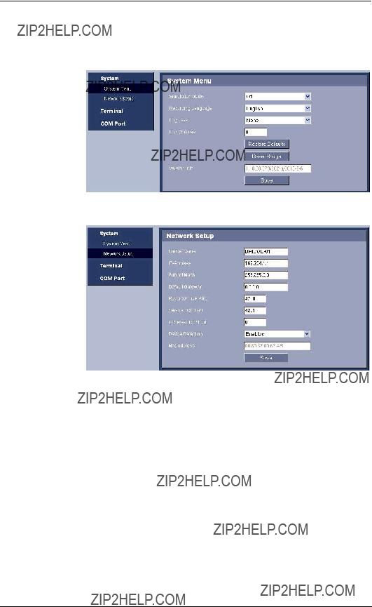
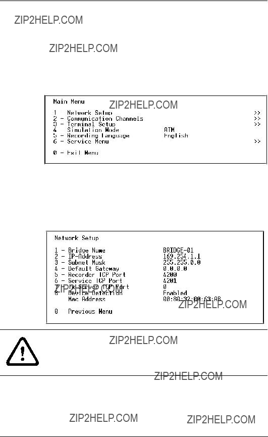
5.2.1System Menu
The System Menu contains settings for bridge operation.

???Simulation Mode: Select the type of device to test the connection between the bridge and the digital recorder. Select this mode to send sample data from the bridge to the digital recorder.
???Recording Language: Select the language that is set on the digital recorder to ensure that characters display correctly.
???Log Level: Ensure that the Log Level setting is None. This setting is used for diagnostic purposes only.
???Log Modules: Ensure that the Log Module setting is zero
(0). This setting is used for diagnostic purposes only.
???Restore Defaults: Resets all COM and Terminal settings to factory defaults. This button does not reset the Network settings.
???Reset Bridge: Reboots the bridge by cycling the power.
???Version Info: Displays the firmware release level for the bridge.
5.2.2Network Setup
The Network Setup enables you to provide a label for the bridge and to configure network settings.
CAUTION!
Changing a parameter on the Network Setup page may interrupt the operation of the ATM/POS Bridge. Contact your network administrator before making any changes.
???Bridge Name: Type an optional name for the bridge in the Bridge Name input box. This name facilitates recognition of the bridge on the network.
???IP Address: Displays the current IP Address for the bridge. You can type a new IP Address in the input box.
???Subnet Mask: Displays the current Subnet Mask for the bridge. You can type a new Subnet Mask in the input box.
???Default Gateway: Displays the current Gateway Address for the bridge. You can type a new Gateway Address in the input box.
???Recorder TCP Port: Displays the TCP port number where the recorder listens for the bridge device. You can type a new port number in the input box.
???Service TCP Port: Displays the TCP port where the bridge listens for CLI commands. (The bridge supports CLI commands which are used to read and change settings in the bridge.)
???Tx Server TCP Port: Displays the TCP port number where the bridge listens for the server that receives transaction data from the POS or ATM devices on the network. You can type a new port number in the input box.
???Device Detection: Enables or disables the Bridge Detection utility to find the bridge on a network.
NOTICE!
It is recommended to disable this feature once the network settings are configured.
???MAC Address: Displays the MAC Address for the bridge. This value cannot be changed.
5.2.3Terminal
The Terminal Setup pages allow you to configure the bridge to accept transactions from the ATM/POS devices connected to the bridge.
???Name: Type an optional name for the terminal. This name facilitates recognition of the terminal on the network
???Device: Select the type of POS or ATM device. You can choose one of these options:
???Specific Device: The bridge converts the characters from the terminal based on the code page setting of the terminal and the recording language selected on the bridge System menu.
???Transparent: The bridge receives all characters from an ATM/POS terminal in a complete line without protocol conversion; then transmits the complete line to a recording device. The bridge does not perform character conversion.
???Capture: The bridge receives all characters from an ATM/POS terminal one character at a time; then transmits an individual character to a recording device. The bridge does not perform character conversion.

???Code Page: Select the code page (character set for a particular language) that the ATM/POS terminal uses to encode transaction data. The selections are:
???PC437 (Latin 1)
???PC858 (Latin II + EURO)
???PC737 (Greek)
???PC775 (Baltic)
???PC855 (Cyrillic)
???PC857 (Turkish)
???Comm Channel: Select one the following channels that connects the terminal to the bridge:
???COM 1 - RS232
???COM 2 - RS232
???COM 3 - RS232 (console)
???COM 4 - RS485
???TCP/IP Server: Select this channel if the ATM/POS terminal connects to the bridge via a TCP/IP network.
???None
???Address: If the Comm Channel is set to TCP/IP, use the Address field to enter one of the following addresses:
???0.0.0.0: The default IP Address that instructs the bridge to accept transactions from any IP Address (or ATM/POS terminal) on the network.
???Specific IP Address: Type the IP Address of a specific terminal to instruct the bridge to accept transactions only from that ATM/POS terminal on this Comm Channel.

5.2.4COM Port
The COM Port page enables you to configure the four physical communication port settings on the bridge.
???Comport Mode: Select the appropriate communication method between the bridge and the terminal:
???Asynchronous
???Mono synchronous
???Bisynchronous
???Bit Synchronous
???Communication Parameters: Select the appropriate settings to match the communication parameters for the terminal connected to this port:
???Baudrate
???Databits
???Parity
???Stopbits
???Flow Control

6Configuration Using HyperTerminal
You can configure the ATM/POS Bridge via a PC HyperTerminal session. The PC is connected to the COM 3 (console) port on the bridge via a serial connection.
For instructions to update the ATM/POS Bridge firmware, refer to Section A Updating Bridge Firmware, page 36.
6.1Connecting the Bridge
1.Ensure that the bridge is connected to the power supply.
2.Connect the supplied console cable to COM Port 3 (console) on the bridge.
3.Connect the other end of the console cable to a serial port on the PC.
6.2Initiating a HyperTerminal Session
1.Launch the HyperTerminal application on the PC. This application is usually found on the Windows Start menu under the Programs
2.Type a name for the new HyperTerminal session and select an icon for the session, then click OK.
3.Select the appropriate COM port number on the PC that is connected to the bridge, then click OK.
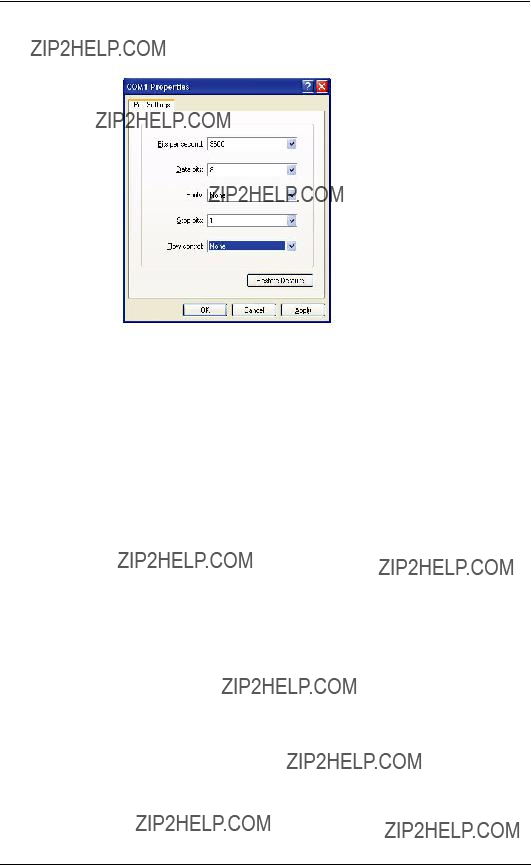
4.Ensure that the settings in the COM Properties dialog box match these settings:
???Bits per second: 9600
???Data bits: 0
???Parity: None
???Stop bits: 1
???Flow control: None
5.Click OK to accept the COM properties and to start the HyperTerminal session.
6.Refer to Section 6.3 Configuring Bridge Operation via HyperTerminal, page 26 for details about configuring the bridge operation via HyperTerminal.
6.3Configuring Bridge Operation via HyperTerminal
After you establish a HyperTerminal connection between a PC and the bridge, use the menu structure to configure the bridge settings. Press the F1 key to open the System Options menu, then select 1 - Network Setup.
6.3.1Network Setup
The Network Setup enables you to provide a label for the bridge and to configure network settings.
CAUTION!
Changing a parameter on the Network Setup page may interrupt the operation of the ATM/POS Bridge. Contact your network administrator before making any changes.

???Bridge Name: Type an optional name for the bridge in the Bridge Name input box. This name facilitates recognition of the bridge on the network.
???IP Address: Displays the current IP Address for the bridge. Select option 2 to enter a new IP Address.
???Subnet Mask: Displays the current Subnet Mask for the bridge. Select option 3 to enter a new Subnet Mask.
???Default Gateway: Displays the current Gateway Address for the bridge. Select option 4 to enter a new Gateway Address.
???Recorder TCP Port: Displays the TCP port number where the recorder listens for the bridge device. You can type a new port number in the input box.
???Service TCP Port: Displays the TCP port where the bridge listens for CLI commands. (The bridge supports CLI commands which are used to read and change settings in the bridge). Select option 6 to enter a new port number.
???Tx Server TCP Port: Displays the TCP port number where the bridge listens for the server that receives transaction data from the POS or ATM devices on the network. Select option 7 to enter a new port number.
???Device Detection: Enables or disables the Bridge Detection utility to find the bridge on a network.
NOTICE!
It is recommended to disable this feature once the network settings are configured.
???MAC Address: Displays the MAC Address for the bridge. This value cannot be changed.

6.3.2Communication Channels
Select the Communication Channel option to configure the four physical communication port settings on the bridge.
Select the appropriate option to configure a specific COM port.
???Comport Mode: Select the appropriate communication method between the bridge and the terminal:
???Asynchronous
???Mono synchronous
???Bisynchronous
???Bit Synchronous
???Communication Parameters: Select the appropriate settings to match the communication parameters for the terminal connected to this port:
???Baudrate
???Databits
???Parity
???Stopbits
???Flow Control

6.3.3Terminal Setup
The Terminal Setup pages allow you to configure the bridge to accept transactions from the devices connected to the bridge.
Select a terminal number to configure the settings for that terminal.
???Name: Select option 1 to type an optional name for the terminal. This name facilitates recognition of the terminal on the network
???Device: Select the type of POS or ATM device. You can choose one of these options:
???Specific Device: The bridge converts the characters from the terminal based on the code page setting of the terminal and the recording language selected on the bridge System menu.
???Transparent: The bridge receives all characters from an ATM/POS terminal in a complete line without protocol conversion; then transmits the complete line to a recording device. The bridge does not perform character conversion.
???Capture: The bridge receives all characters from an ATM/POS terminal one character at a time; then transmits an individual character to a recording device. The bridge does not perform character conversion.

???Code Page: Select the code page (character set for a particular language) that the ATM/POS terminal uses to encode transaction data. The selections are:
???PC437 (Latin 1)
???PC858 (Latin II + EURO)
???PC737 (Greek)
???PC775 (Baltic)
???PC855 (Cyrillic)
???PC857 (Turkish)
???Comm Channel: Select option 4 to select one the following channels that connects the terminal to the bridge:
???COM 1 - RS232
???COM 2 - RS232
???COM 3 - RS232 (console)
???COM 4 - RS485
???TCP/IP Server: Select this channel if the ATM/POS terminal connects to the bridge via a TCP/IP network.
???None:
???Address: Select option 5 to configure the address.
If the Comm Channel is set to TCP/IP, use the Address field to enter one of the following options:
???0.0.0.0: The default IP Address that instructs the bridge to accept transactions from any IP Address (or ATM/POS terminal) on the network.
???Specific IP Address: Type the IP Address of a specific terminal to instruct the bridge to accept transactions only from that ATM/POS terminal on this Comm Channel.
6.3.4Simulation Mode
Use the Simulation Mode to select the type of device to test the connection between the bridge and the digital recorder. Select this mode to send sample data from the bridge to the digital recorder.
This setting is set to Off for normal operation.
6.3.5Recording Language
Select the language that is set on the digital recorder to ensure that characters display correctly.
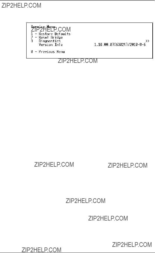
6.3.6Service Menu
The System Menu contains settings for bridge operation.
???Restore Defaults: Resets all COM and Terminal settings to factory defaults. This button does not reset the Network settings.
???Reset Bridge: Reboots the bridge by cycling the power.
???Diagnostics: Select this option to perform the EEPROM diagnostic test.
???Version Info: Displays the firmware release level for the bridge.

7Troubleshooting
If you are unable to capture transaction data, follow these steps:
1.Check all cable connections.
2.Check the TCP/IP network connection with the ATM/POS Bridge. Ensure that the IP Address, Subnet Mask, and Gateway Address are valid and appropriate for the network.
3.If the recorder has established communication with your bridge and you cannot capture transaction data, use the simulation mode (refer to Section 5.2.1 System Menu, page 18) to send sample transactions to the recorder.
4.Check the COM port settings in the bridge. If the transaction data is being recorded, but displays the wrong characters, check the COM port settings. The language setting in the bridge must be the same as the recorder language setting. Refer to Section 5.2.1 System Menu, page 18.
5.Check that the ATM/POS license is enabled in the recorder, if necessary.

8Technical Data
Electrical
Electromagnetic Compatibility


AUpdating Bridge Firmware
Follow the steps below to update the firmware on the ATM/ POS Bridge.
1.Download the Zip file for the ATM/POS Bridge firmware from the Bosch Security Systems Web site (www.boschsecurity.com).
2.Unzip the firmware update file into a folder on the PC that you will use to update the bridge.
3.Run the downloadwizard.exe file to start the update process. The PC displays the initial wizard screen.
4.Click Next to proceed to the Prepare the Bridge step.

a.Unplug the power cable from the bridge.
b.Connect the supplied console cable to COM Port 3 (console) on the bridge and to a COM port on the PC.
c.Connect the supplied power adapter to the bridge and to the main power.
The red LED light on top of the bridge flashes short pulses to indicate that the bridge is in download mode.
NOTICE!
if the console download cable is attached to the PC via a low- end USB to Serial adapter, the firmware download attempt may take several attempts before it succeeds. Bosch recommends the SIIG USB to Serial serial adapter, a
5.Click Next to select the PC COM port and to configure the bridge communication settings.
Change the settings for the Baud rate, Data, Parity, and
Stop parameters to match the settings on the PC.
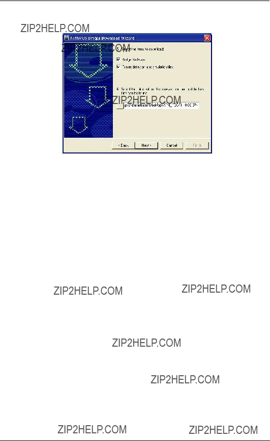
6.Click Next to select the download parameters.
7.Click the check boxes to download the Bridge Software and the Printer definition and simulation files. A check mark indicates that the process will update the specific files.
8.Select the folder where the firmware and printer definition files are stored.
By default, the wizard searches for the file in the same directory that contains the downloadwizard.exe file.
9.To navigate to a different folder, click the ... button to select another directory. Then, click OK to return to the wizard.
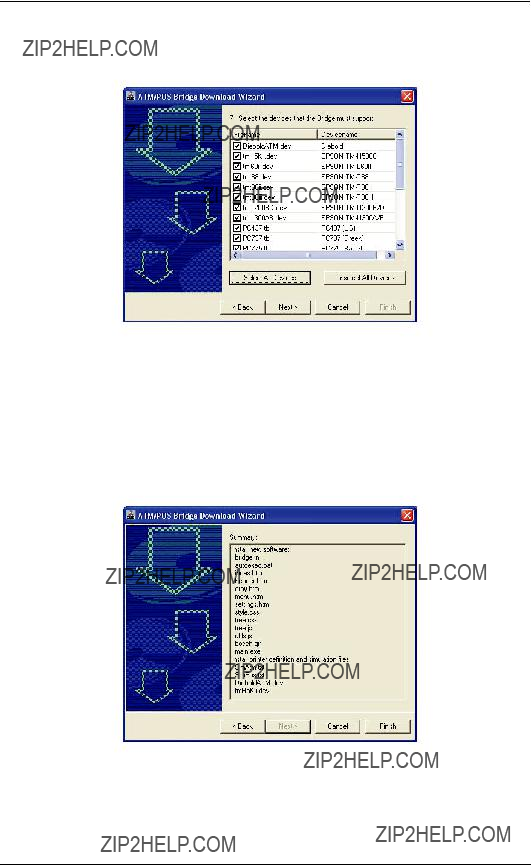
10.Click Next to select the device profiles that are stored on the bridge.
???Select individual check boxes to select specific device profiles.
???Click the Select All Devices to select all device profiles.
???Click Unselect All Devices to clear the check boxes for all device profiles.
11.Click Next to view a summary of the download settings and to start the update process.

12.Click Finish to accept the settings and to start the firmware update. If you receive an error message, refer to
Page 41.
13.Click Yes to overwrite the existing files on the bridge. The wizard displays a download progress screen.
DO NOT interrupt the update process.
14.Click OK once the upload process is complete.
15.Disconnect the power cable and the console cable from COM Port 3 on the bridge.
16.Reconnect a serial cable from a terminal to COM Port 3, if required.
NOTICE!
Ensure that the console cable is disconnected from the bridge before reconnecting the power.
17. Reconnect the power cable to the bridge.
Troubleshooting Bridge Firmware Update
Use the following steps to correct the firmware settings If you receive the following error during the firmware update process:
1.Click OK to acknowledge the error.
2.Click the Cancel button to stop the process and to quite the wizard.
3.
4.Follow the process until you reach the communications setup wizard screen. Use the following values for the communication settings:
???Baud Rate: 19200
???Data: 8 bits
???Parity: None
???Stop: 1 bit
5.Continue through the wizard screens to start the upload process.


Bosch Security Systems, Inc.
www.boschsecurity.com
?? Bosch Security Systems, Inc., 2010