LTC9316/00P
Security Systems
EN
Installation Manual
Standard Pole
LTC9316/00P
Security Systems
EN
Installation Manual
Standard Pole

1 DESCRIPTION
The LTC 9316/00P units are 16 foot steel mounting poles for use with Unity?? Domes, AutoDomes??, and the LTC 9320 Series of Outdoor Fixed Domes.
2 UNPACKING
Unpack carefully. This is mechanical equipment and should be handled with care.
Check for the following:
???Packet Assembly for LTC 9316/00P:
1Bosch Adapter Plate.
43/8 x
4
45/16 Stainless Steel Flat Wash.
43/8 Stainless Steel Split Lockwasher.
45/16 Stainless Steel Split Lockwasher.
1Wiring grommet
1Conduit plug
1Installation Instructions (This Manual).
???Steel Pole
If an item appears to have been damaged in shipment, replace it properly in its carton and notify the shipper. If any items are missing, notify your Bosch Security Systems Sales Representative or
Customer Service.
The shipping carton is the safest container in which the unit may be transported. Save it for possible future use.
4 INSTALLATION
This installation should be made by quali???ed service personnel and conform to the National Electrical Code and applicable local codes.
! Please read these instructions carefully before proceeding, and heed all cautions.
4.1Site Preparation
NOTE: Special attention must be paid to the size of the ! wiring conduit and its location within the concrete
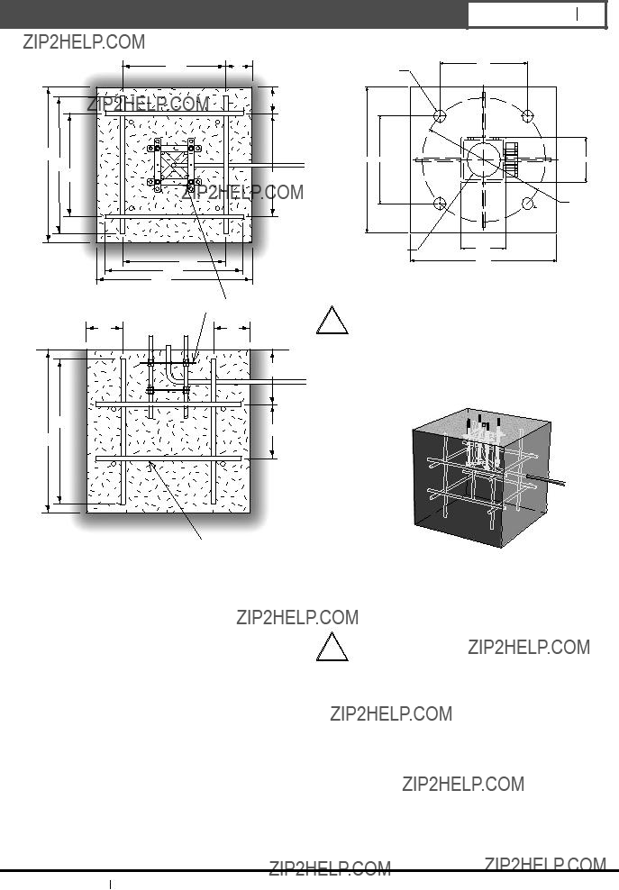
foundation and jig (if applicable). The Wiring Conduit can be up to 2" in diameter. Use reducers if necessary. Also, make sure that the Wiring Conduit is in the center of the foundation and Anchor Jig during installation (Figure 1).
Mounting
Bolts
Figure 1 Mounting Bolts & Wiring Conduit Location
3 SERVICE
If the unit ever needs repair service, the customer should contact the nearest Bosch Security Systems Service Center for authorization to return and shipping instructions.
Service Centers
U.S.A.: Phone:
Canada:
Europe, Middle East & Asia Paci???c Regions:
For additional information, see www.boschsecuritysystems.com
1.Select a suitable site for the LTC 9316/00P and prepare the pad site using a hole 36" x 36" x 36" deep. The top of the concrete foundation should be ???ush with the ground.
CAUTION: Be sure that there are no underground electric or
!phone cables or gas or water lines in the area where the pole will be located.
2.To help reinforce the concrete foundation, place (12) 1/2" diameter
x32" long Reinforcement Bars (rebar) as shown in Figure 2. Use suitable preparation methods to place the rebar.
Bosch Security Systems 10 October 2003
EN 3
4.000
O 11.000
Reinforcement bars (12)
Figure 2 Reinforcement Bars
3.FOR ANCHOR BOLT INSTALLATIONS:
Pour concrete per manufacturer's directions, making sure that the wiring conduit is in the center of the pad. See Figure 3 (next page) for dimensions of the bolt pattern and suspend appropriate bolts in the concrete around the wiring conduit. Leave 2" to 3" of the Bolts protruding above the pad. If you are using leveling nuts, leave 4" to 6" protruding.
Figure 4 View of Concrete Foundation
4.2Installation
1.Place the pole on the pad with the holes on the Base Plate aligned with the bolts of the anchor bolts or anchor jig (Figure 5).
2.Remove the access opening plates at the bottom and top.
Bosch Security Systems 10 October 2003

Access opening plates
Bolts or anchor jig
Pad
Figure 5 Placement of Pole on Pad
3.Insert the wiring into the 3" diameter hole in the base of the pole. Be sure all slack is pulled completely through.
4.Insert connecting wiring into the bottom access opening, run through the pole up to the top access opening. Insert the end rough the housing connecting hole. Close the top access opening and make necessary wiring connections at the bottom access opening (Figure 6).
Top access opening
Figure 6 Connecting Wiring Through Pole
5.Slowly lift the pole into the upright position, aligning the holes of the Base Plate with the Bolts in the concrete pad (FigurBosch Security Systems10 October 2003e 7).
Figure 7 Lifting the Pole into Position
CAUTION: Pull all slack in the wiring as you lift the pole into position to keep from pinching and possible damage.
6.Ensure that the pole is vertical on all sides. Use a bubble level or plumb bob to check.
7.Secure the pole to the pad with fasteners (Figure 8).
Nut
Lock Washer
Flat Washer
Figure 8 Securing the Pole to the Pad
4.3Mounting the AutoDome??
1.Align the holes of the AutoDome adapter plate with the holes on the mounting plate at the top of the pole (Figure 9).
Bosch Security Systems 10 October 2003
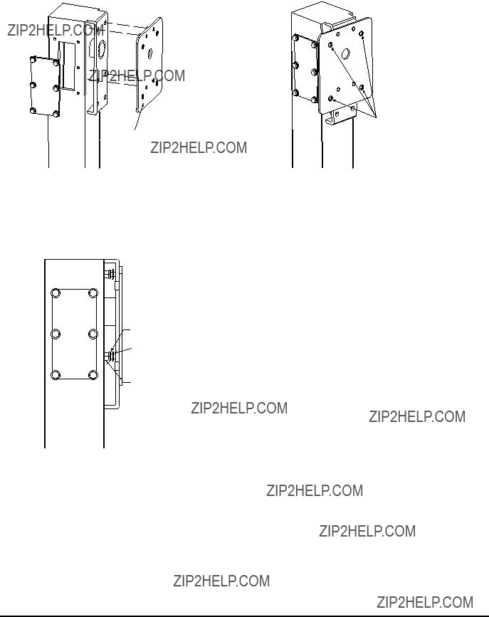
Mount the LTC 9540/xx
Adapter PlateWall Bracket Using
These Holes
Figure 9 Aligning Adapter Plate with Mounting Plate
2.Attach the LTC 9540/xx Wall Bracket adapter plate, using the provided hex head nuts and bolts, flat washers, and lockwashers (see Figure 10).
Figure 11 Mounting the LTC 9540/xx Wall Bracket
5 SPARE PARTS
Lockwashers
Flat Washers
Figure 10 Attaching the Adapter Plate
3.Attach the LTC 9540/xx Wall Bracket to the adapter plate using recommended 8 mm

?? 2005 Bosch Security Systems GmbH