Divar MR Digital Video Recorder
Type numbers
en Operation Manual_en
Divar MR Digital Video Recorder
Type numbers
en Operation Manual_en

Table of contents


1 Safety
1.1Important safety instructions
Read, follow, and retain for future reference all of the following safety instructions. Heed all warnings on the unit and in the operating instructions before operating the unit.
1.Cleaning - Unplug the unit from the outlet before cleaning. Follow any instructions provided with the unit. Generally, using a dry cloth for cleaning is sufficient, but a moist
2.Heat Sources - Do not install the unit near any heat sources such as radiators, heaters, stoves, or other equipment (including amplifiers) that produce heat.
3.Ventilation - Any openings in the unit enclosure are provided for ventilation to prevent over- heating and ensure reliable operation. Do not block or cover these openings. Do not place the unit in an enclosure unless proper ventilation is provided, or the manufacturer???s instructions have been adhered to.
4.Water - Do not use this unit near water, for example near a bathtub, washbowl, sink, laun- dry basket, in a damp or wet basement, near a swimming pool, in an outdoor installation, or in any area classified as a wet location. To reduce the risk of fire or electrical shock, do not expose this unit to rain or moisture.
5.Object and liquid entry - Never push objects of any kind into this unit through openings as they may touch dangerous voltage points or
6.Lightning - For added protection during a lightning storm, or when leaving this unit unattend- ed and unused for long periods, unplug the unit from the wall outlet and disconnect the cable system. This will prevent damage to the unit from lightning and power line surges.
7.Controls adjustment - Adjust only those controls specified in the operating instructions. Improper adjustment of other controls may cause damage to the unit. Use of controls or adjustments, or performance of procedures other than those specified, may result in hazard- ous radiation exposure.
8.Overloading - Do not overload outlets and extension cords. This can cause fire or electrical shock.
9.Power cord and plug protection - Protect the plug and power cord from foot traffic, being pinched by items placed upon or against them at electrical outlets, and its exit from the unit. For units intended to operate with 230 VAC, 50 Hz, the input and output power cord must comply with the latest versions of IEC Publication 227 or IEC Publication 245.
10.Power disconnect - Units with or without ON/OFF switches have power supplied to the unit whenever the power cord is inserted into the power source. The power cord is the main power disconnect device for switching off the voltage for all units.
11.Power sources - Operate the unit only from the type of power source indicated on the label. Before proceeding, be sure to disconnect the power from the cable to be installed into the unit.
12.Servicing - Do not attempt to service this unit yourself. Opening or removing covers may expose you to dangerous voltage or other hazards. Refer all servicing to qualified service per- sonnel.
13.Damage requiring service - Unplug the unit from the main AC power source and refer servic- ing to qualified service personnel when any damage to the equipment has occurred, such as:
???the power supply cord or plug is damaged;
???exposure to moisture, water, and/or inclement weather (rain, snow, etc.);
???liquid has been spilled in or on the equipment;
???an object has fallen into the unit;
???unit has been dropped or the unit cabinet is damaged;
???unit exhibits a distinct change in performance;

???unit does not operate normally when the user correctly follows the operating instruc- tions.
14.Replacement parts - Be sure the service technician uses replacement parts specified by the manufacturer, or that have the same characteristics as the original parts. Unauthorized substi- tutions could void the warranty and cause fire, electrical shock, or other hazards.
15.Safety check - Safety checks should be performed upon completion of service or repairs to the unit to ensure proper operating condition.
16.Installation - Install in accordance with the manufacturer???s instructions and in accordance with applicable local codes.
17.Attachments, changes or modifications - Only use attachments/accessories specified by the manufacturer. Any change or modification of the equipment, not expressly approved by Bosch, could void the warrantee or, in the case of an authorization agreement, authority to operate the equipment.
1.2Safety precautions
DANGER! High risk:
This symbol indicates an imminently hazardous situation such as ???Dangerous Voltage??? inside the product.
If not avoided, this will result in an electrical shock, serious bodily injury, or death.
WARNING! Medium risk:
Indicates a potentially hazardous situation.
If not avoided, this could result in serious bodily injury or death.
CAUTION! Medium risk:
Indicates a potentially hazardous situation.
If not avoided, this may result in minor or moderate injury.
Alerts the user to important instructions accompanying the unit.
CAUTION! Low risk: (without safety alert symbol) Indicates a potentially hazardous situation.
if not avoided, this may result in property damage or risk of damage to the unit.
NOTICE!
This symbol indicates information or a company policy that relates directly or
indirectly to the safety of personnel or protection of property.
1.3Important Notices
Accessories - Do not place this unit on an unstable stand, tripod, bracket, or mount. The unit may fall, causing serious injury and/or serious damage to the unit. Use only with the cart, stand, tripod, bracket, or table specified by the manufacturer. When a cart is used, use caution and care when moving the cart/apparatus combination to avoid injury from

Battery replacement - A lithium battery is located inside the unit enclosure. To avoid danger of explosion, replace the battery as per instructions. Replace only with the same or equivalent type rec- ommended by the manufacturer. Dispose of the replaced battery in an environmentally friendly way. Refer all servicing to qualified service personnel.
CAUTION!
Class I Laser Product
Invisible laser radiation when open. Avoid exposure to beam.
This warning is applicable only to those models that contain an internal DVD burner which uses a certified Class I laser.
Coax grounding:
???Ground the cable system if connecting an outside cable system to the unit.
???Connect outdoor equipment to the unit???s inputs only after this unit has had its grounding plug connected to a grounded outlet or its ground terminal is properly connected to a ground source.
???Disconnect the unit???s input connectors from outdoor equipment before disconnecting the grounding plug or grounding terminal.
???Follow proper safety precautions such as grounding for any outdoor device connected to this unit.
U.S.A. models only - Section 810 of the National Electrical Code, ANSI/NFPA No.70, provides informa- tion regarding proper grounding of the mount and supporting structure, grounding of the coax to
a discharge unit, size of grounding conductors, location of discharge unit, connection to grounding electrodes, and requirements for the grounding electrode.
NOTICE!
This device is intended for use in public areas only.
U.S. federal law strictly prohibits surreptitious recording of oral communications.
Disposal - Your Bosch product was developed and manufactured with
Environmental statement - Bosch has a strong commitment towards the environment. This unit has been designed to respect the environment as much as possible.
NOTE: Wear required grounded wrist straps and observe proper ESD safety precautions when han- dling the
Fuse rating - For security protection of the device, the branch circuit protection must be secured with a maximum fuse rating of 16A. This must be in accordance with NEC800 (CEC Section 60).
Grounding and polarization - This unit may be equipped with a polarized alternating current line plug (a plug with one blade wider than the other blade). This safety feature allows the plug to fit into
the power outlet in only one way. If unable to insert the plug fully into the outlet, contact a locally certified electrician to replace the obsolete outlet. Do not defeat the safety purpose of the polarized plug.
Alternately, this unit may be equipped with a

Moving - Disconnect the power before moving the unit. Move the unit with care. Excessive force or shock may damage the unit and the hard disk drives.
Outdoor signals - The installation for outdoor signals, especially regarding clearance from power and lightning conductors and transient protection, must be in accordance with NEC725 and NEC800
(CEC Rule
Permanently connected equipment - Incorporate a readily accessible disconnect device in the build- ing installation wiring.
Pluggable equipment - Install the socket outlet near the equipment so it is easily accessible.
Power disconnect - Units have power supplied whenever the power cord is inserted into the power source. The power cord is the main power disconnect for all units.
???Ventilation - Do not place this unit in a
???Mechanical loading - Properly mount the equipment in a rack to prevent a hazardous condi- tion due to uneven mechanical loading.
SELV - All the input/output ports are Safety Extra Low Voltage (SELV) circuits. SELV circuits should only be connected to other SELV circuits.
Video loss - Video loss is inherent to digital video recording; therefore, Bosch Security Systems can- not be held liable for any damage that results from missing video information. To minimize the risk of lost digital information, Bosch Security Systems recommends multiple, redundant recording sys- tems, and a procedure to back up all analog and digital information.
FCC & ICES Information (residential applications)
(U.S.A. and Canadian Models Only)
This equipment has been tested and found to comply with the limits for a Class B digital device, pursuant to part 15 of the FCC Rules. These limits are designed to provide reasonable protection against harmful interference in a residential installation. This equipment generates, uses, and can radiate radio frequency energy and, if not installed and used in accordance with the instructions, may cause harmful interference to radio communications. However, there is no guarantee that inter- ference will not occur in a particular installation. If this equipment does cause harmful interference to radio or television reception, which can be determined by turning the equipment off and on, the user is encouraged to try to correct the interference by one or more of the following measures:
???reorient or relocate the receiving antenna;
???increase the separation between the equipment and receiver;
???connect the equipment into an outlet on a circuit different from that to which the receiver is connected;
???consult the dealer or an experienced radio/TV technician for help.
Intentional or unintentional modifications, not expressly approved by the party responsible for com- pliance, shall not be made. Any such modifications could void the user???s authority to operate the equipment. If necessary, the user should consult the dealer or an experienced radio/television tech- nician for corrective action.
The user may find the following booklet, prepared by the Federal Communications Commission, helpful: How to Identify and Resolve
Disclaimer
Underwriter Laboratories Inc. (???UL???) has not tested the performance or reliability of the security or signaling aspects of this product. UL has only tested fire, shock and/or casualty hazards as outlined in UL???s Standard(s) for Safety for Information Technology Equipment, UL
UL MAKES NO REPRESENTATIONS, WARRANTIES, OR CERTIFICATIONS WHATSOEVER REGARDING
THE PERFORMANCE OR RELIABILITY OF ANY SECURITY OR
THIS PRODUCT.
Copyright
This user guide is the intellectual property of Bosch Security Systems and is protected by copyright. All rights reserved.

Trademarks
All hardware and software product names used in this document are likely to be registered trade- marks and must be treated accordingly.
NOTICE!
This operation manual has been compiled with great care and the information it contains has been thoroughly verified. The text was complete and correct at the time of printing. The ongoing development of the products may mean that the content of the user guide can change without notice. Bosch Security Systems accepts no liability for damage resulting directly or indirectly from faults, incompleteness or discrepancies between the user guide and the product described.
More information
For additional information, please contact the Bosch Security Systems location nearest you or visit our web site at www.boschsecurity.com

2 Introduction
2.1Features
???Stable embedded operating system.
???Small ???le sizes with
???Internal storage capacity to 2TB.
???NTSC and PAL selectable video format.
???Full realtime recording:
-Up to 480IPS@352 X 240:
-Up to 400IPS@352 X 288:
-Up to 240IPS@352 X 240:
-Up to 200IPS@352 X 288:
???Various recording resolutions and quality levels:
-4CIF (704x480), 2CIF (704x240), CIF(352x240) : NTSC
-4CIF (704x576), 2CIF (704x288), CIF(352x288) : PAL.
-5 step quality level (Lowest, Low, Normal, High, Best).
???Easy operation using various user interface & user friendly GUI:
-Optical mouse, Full function IR remote controller, Jog/Shuttle
???Powerful multiplex functions:
-Simultaneous live display, recording, playback, network transmission,
???Various search functions:
-Date/time search, event search, bookmark search, smart search.
???Event data protection by event partition recording.
???
???Motion event recording and preview test function of motion sensitivity.
???Recording image rate & quality adjustment per individual camera.
???Powerful record scheduling.
???Instant playback in live mode.
???Perfect audio/video synchronization.
???Automatic backup by schedule.
???Image authentication (Watermark).
???Three USB 2.0 ports for backup interface.
???Setup con???guration export/import with USB memory stick or network.
???Easy system software update with USB memory stick or network.
???Control Center PC software can manage max 100 DVR.
???Max ???ve clients can access one DVR server simultaneously.
???Network bandwidth throttle:
-Automatically adjust a bandwidth according to network speed status of unit.
???Remote alarm noti???cation via PC software or
???Time and date sync from NTP server.
???Daylight saving mode.
???Covert camera protection.
???User management (User level control).
???PTZ Control:
-For more details see "8.2.4 Supported PTZ camera list".
-Dome camera telemetry control (Dome OSD control).
Note:
Model
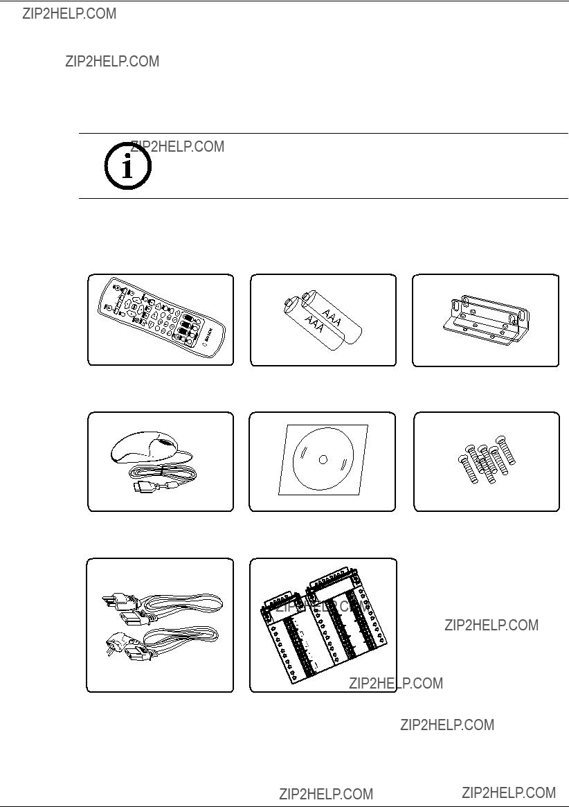
2.2Accessories
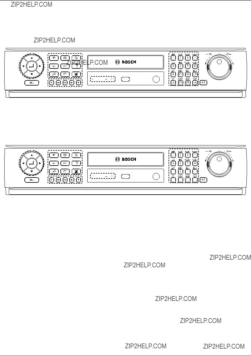
2.3Front panel
Figure 2.2 Front panel
aArrow Buttons (b B v V): Select or move between the menu options.  (ENTER): Con???rms menu selections.
bFunction Buttons
 : Displays the setup menu.
 : Display the monitor A control menu to set the screen mode to full, 4, 6, 8, 9 or 16 screens. Set the video output signal to VGA mode.
 : Display the monitor B control menu. Set the video output signal to MON A mode.
 : Switches the unit to PTZ mode to control the connected PTZ camera.
 : Press to see different multiscreen modes.
 : View all channels in sequence.
 : Displays the search menu.
 : Starts or stops instant recording of the selected camera (yellow border).
 : Cancels alarm activation and returns the system to the condition before the alarm was activated.

cDisc Tray
dChannel Buttons
You can input a number with the channel buttons. You can also use the channel buttons for
???The LED in the button indicates the status as follows:
-Off: The current status is for live mode.
-Red: Recording mode.
Blinks when an event occurs.
???(1) OPEN: Opens or closes the disc tray
???(2) LOCK: Displays the lock menu to change the user type or disable the system
operation.
???(3) ZOOM
???(5) LOG: Displays or removes the System Log List.
???(6) INFO: Displays or removes system information.
???(7) FOCUS
???(9) COPY: Copies the recording data to an external device.
???(10) MARK: Sets the mark point for recording search. You can set the mark point during the single channel playback of recorded data.
???(11) IRIS
???(13) SET: Registers the PTZ camera's preset position.
???(14) CLEAR: Deletes a memorized preset position of the PTZ camera.
???(15) MOVE: Moves the PTZ camera to the preset position.
???(16) TOUR: Tours all registered preset positions in the PTZ camera.
eShuttle Ring: Fast forward or reverse picture search when the dial is rotated.
fJOG Dial: Allows a forward or reverse frame search.
In pause mode, plays recorded images frame by frame through rotation. Increases or decreases the options value.
gESC: Use to return to previous level or to exit menu system without saving.
hPlayback Control Buttons
-X: Pauses playback.
-m: Reverse search the recorded images.
-bB: Playback or reverse playback of recorded images.
-M: Forward search the recorded images.
-x: Stops playback.
iIndicators
 : Lights when the DVR is powered.
 : Blinks when the HDD is accessed.
 : Lights when the alarm is active.
 : Lights when a network cable is connected.
jUSB Port
Connect an external USB device for back up or playback.
kRemote Sensor
Point the remote control here.
lALT
Activate if you use the

2.4Back panel
Figure 2.3 Back panel
aVIDEO INPUT: Connect the camera???s video output to these BNC connectors.
bLOOP OUT: The signal from VIDEO INPUT connector is looped out to this connector.
cPower Cord Inlet (AC IN): Connect the power plug.
dAUDIO OUT: Connect the audio input signal of an external device.
eBIPHASE: Connect a pan/tilt/zoom control unit via the supplied
fAUDIO IN: Connect the audio output of an external device.
gALARM I/O: Connect up to 16 alarm inputs via the supplied
h
iKBD IN: Connect a Bosch CCTV keyboard unit to the KBD IN socket.
jCOM1: Use to connect to a host device equipped with
kETHERNET Port: Connect the ethernet 10/100Mbps network cable for controlling this unit via a PC network.
lMON B (BNC Type Connector): Connect to spot monitor or display device.

mMON A (BNC Type Connector): Connect to main monitor or display device.
nVGA: Connect a VGA monitor.
oUSB Ports: Connect optional extension USB devices (e.g. mouse, memory stick).
2.5Remote Control
Figure 2.4 Remote control.
???LOCK: Displays the lock menu to change user type or disable system operation.
???ACK: Cancels alarm activation and returns the system to the condition before the alarm was activated.
??? : Display the monitor A control menu to set the screen mode to full, 4, 6, 8, 9 or 16 screens.
??? : Display the monitor B control menu to allow spot monitor control.
??? : Press to see different multiscreen modes.
??? : View all channels in sequence.
???ESC: Use to return to previous level or to exit menu system without saving.
???MENU: Displays the setup menu.
???Arrow Buttons (b B v V): Selects or moves between the menu options.

???ENTER: Con???rms menu selections or go to full screen of a selected camera in multiscreen. Pressing this key again to return from full screen to multiscreen.
???COPY: Copies the recorded data to an external device.
???SEARCH: Displays the search menu.
???MARK: Sets the mark point for recording search. You can set the mark point during the single channel playback of recorded data.
???PAUSE (X): Pauses playback.
???STOP(x): Stops playback.
???REC (z): Starts or stops recording.
???m / c: Reverse search; Searches the recorded images in reverse sequence.
???bB: Playback or reverse playback of recorded images.
???M / C: Forward search; Searches the recorded images in forward sequence.
???Number Buttons (0,
???INFO: Displays or removes the system information window.
???LOG: Displays or removes the System Log List window.
???PTZ: Switches this unit to PTZ mode to control the connected PTZ camera.
???TOUR: Tours all registered preset positions in the PTZ camera.
???ZOOM + /
???FOCUS + /
???IRIS + /
???PRESET
-SET: Registers the PTZ camera???s preset positions.
-CLEAR: Deletes a memorized preset position.
-MOVE: Moves the camera to the preset position.
???ID: Set the appropriate DVR system ID to operate via the IR Remote Controller when using multiple DVRs. Press the ID button, then press the number button within 2 seconds to select the system ID of the DVR. If you set the system ID to ???0???, you can control multiple DVR at the same time.


3 Connections and settings
Precautions
???There are various ways to connect the unit, depending on the camera and other equipment. Please refer to the camera manual or the manuals for other devices as necessary for additional connection information.
???Be sure to switch off the camera before installation and connection.
???Default the main monitor (MON A) will start up in VGA mode. See section 3.12 for selection of the main monitor type.
3.1Basic connection overview
c
Figure 3.1 Basic connection overview

aConnect the cameras to the BNC
bConnect the Monitor, DVR, VCR, or others to the video out BNC.
cConnect the power cord to the unit.
dConnect an audio ampli???er.
eConnect a pan/tilt/zoom control unit via the supplied
fConnect up to 16 (alarm) inputs or connect up to 8 alarm output relays via the supplied
gConnect PTZ cameras or DVRs.
hConnect a Bosch CCTV keyboard unit to the KBD IN socket.
iConnect audio (line input).
jConnect to your network via the Ethernet port or use the RS232 connector to connect directly to a PC serial port (for service purposes).
kConnect monitor B to the BNC output MON B.
lConnect monitor A to the BNC output MON A.
mConnect a VGA monitor.
nConnect optional extension USB devices (e.g. mouse, memory stick).
3.2Camera connections
Connect cameras to the unit using
signal to other equipment. The camera input connectors are
If the camera signal is
3.3Monitor connections
Connect the unit to the monitors via
If the monitor has a
3.4Connecting the
The serial RS232 console port connector is used to connect a PC to the unit for service purposes. Use a
This terminal is compliant with the
3.5CCTV keyboard connections
The keyboard input connector is used to connect an external CCTV keyboard to the unit. Connect the keyboard to the KBD IN connector.
For short distances (up to 30m), standard
For distances over 30m between keyboard and Divar MR, the Keyboard Extension Kit (LTC 8557) must be used. This kit provides junction boxes, cables and the appropriate power supply for the external keyboards. The recommended cable type is Belden 9841 or equivalent.
3.6Network connection
3.6.1LAN connection
Connect the LAN port to an available 10/100
3.6.2Automatic network configuration
The DVR can automatically obtain and configure the network interface via DHCP.
3.6.3Manually configure network
The DVR may be manually configured by assigning an IP address, subnet mask, gateway and DNS.
3.7Connecting the USB device
3.7.1USB memory device
Insert the memory device into the USB port. The system automatically recognizes the device.
Using a USB memory device the system software can be easily upgraded.
3.7.2USB backup device
Connect the USB cable of the USB backup device to the USB port on the rear panel of the unit.
(Example: HDD or other external storage).
3.7.3Mouse
Connect the USB mouse for function control of the unit.
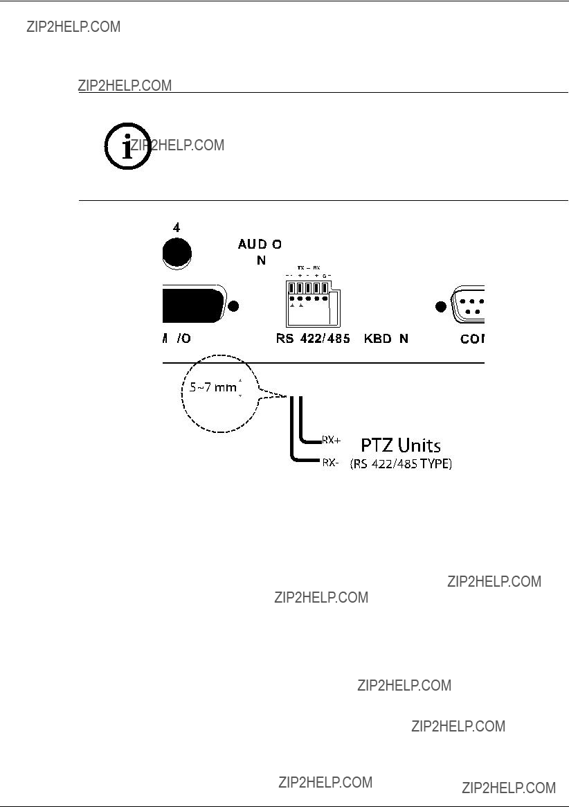
3.8Connecting a
Use this port to connect PTZ cameras.
Connect the PTZ serial communication lines to the
Notes:
???When connecting lines, connect the TX- of the DVR to RX- of the PTZ unit and TX+ of the DVR to RX+ of the PTZ unit correctly.
???Recommended initial data are 9600 Baud Rate, 8 Data bits, 1 Stop bit and No parity.
???When connecting PTZ cameras to DVRs it is necessary to set the setup menu for this unit according to the
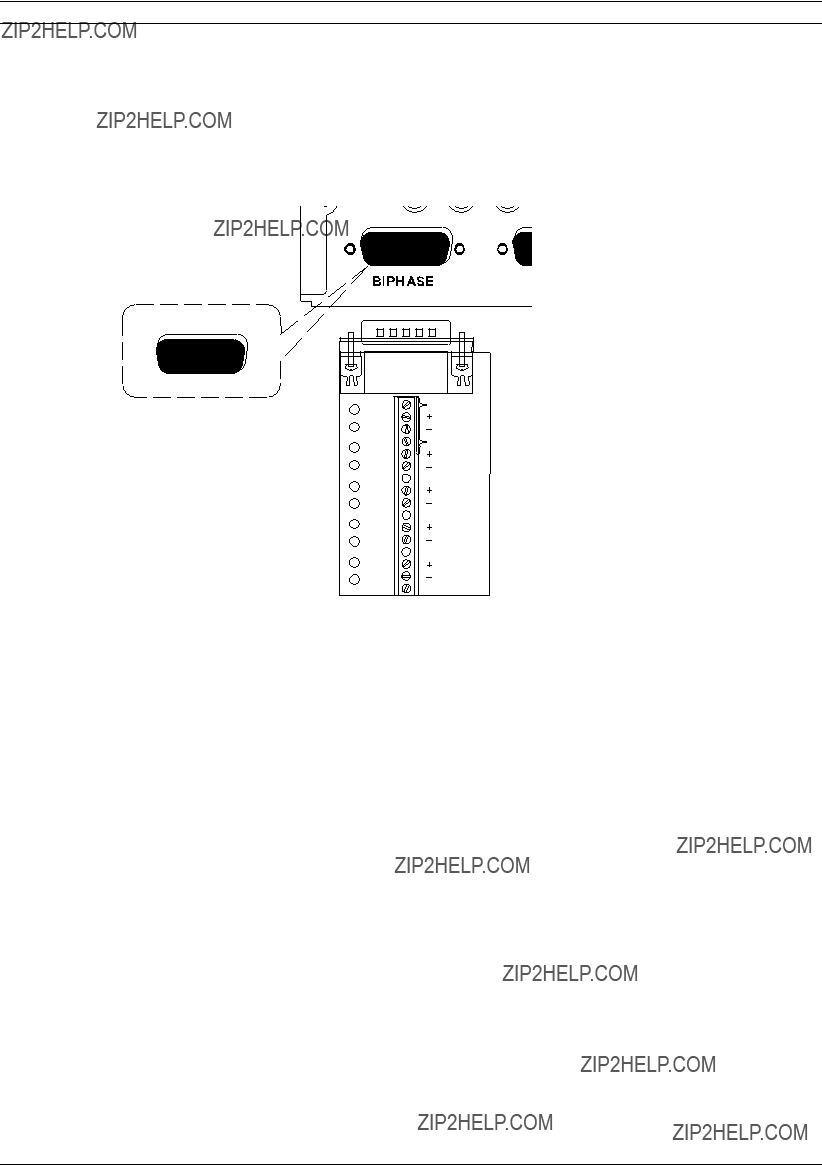
3.9Connecting the BIPHASE port
The Biphase port is used for connecting cameras that use Bosch Biphase communications to control camera positioning. Five Biphase outputs are provided for dome camera and pan, tilt and zoom control. The screw terminal connection board supplied with the unit simplifies all Biphase connections to the unit.
Maximum cable length per Biphase output is 1.5 kilometers (0.9 miles). Maximum number of controllable cameras is 4 per Biphase output.
8 1
15 9
SHIELD
 CTRL 1
SHIELD
 CTRL 2

 SHIELD
 CTRL 3

 SHIELD
 CTRL 4

 SHIELD
 CTRL 5
 SHIELD
Figure 3.3 Biphase port connector
BIPHASE port -
Table 3.2 Biphase pin configuration
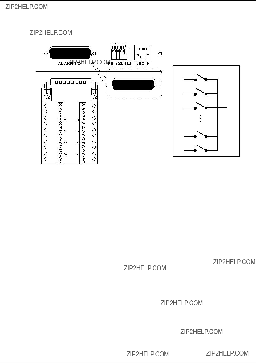
3.10Connecting the ALARM I/O port
Alarm inputs and outputs are supplied via a
Figure 3.4 Alarm I/O port connector
3.10.1Connecting the Inputs
Each (alarm) input line can be switched by a relay contact from devices such as pressure pads, passive infra red detectors, smoke detectors and similar devices.
Wire them as either N/O (Normally Open) or N/C (Normally Closed). You can configure the alarm inputs as N/O or N/C in the menu system. The default is N/O.
3.10.2Connecting the Alarm Outputs
The eight alarm output relays respond to input alarms and triggers. You can configure the alarm outputs as N/O or N/C in the menu system. The relays are active for the duration of the driving event. Connect the application to the alarm output relays (resistive loads only). Do not exceed 1A 30V DC, 0.3A 125V AC on an alarm output relay???s contacts. The contacts must not be used at AC line voltages.
ALARM I/O -
3.11 System operation
Default monitor setting is VGA.
1.Turn on the unit. System booting will commence. The BOSCH logo image will be displayed on the main monitor during the system booting.
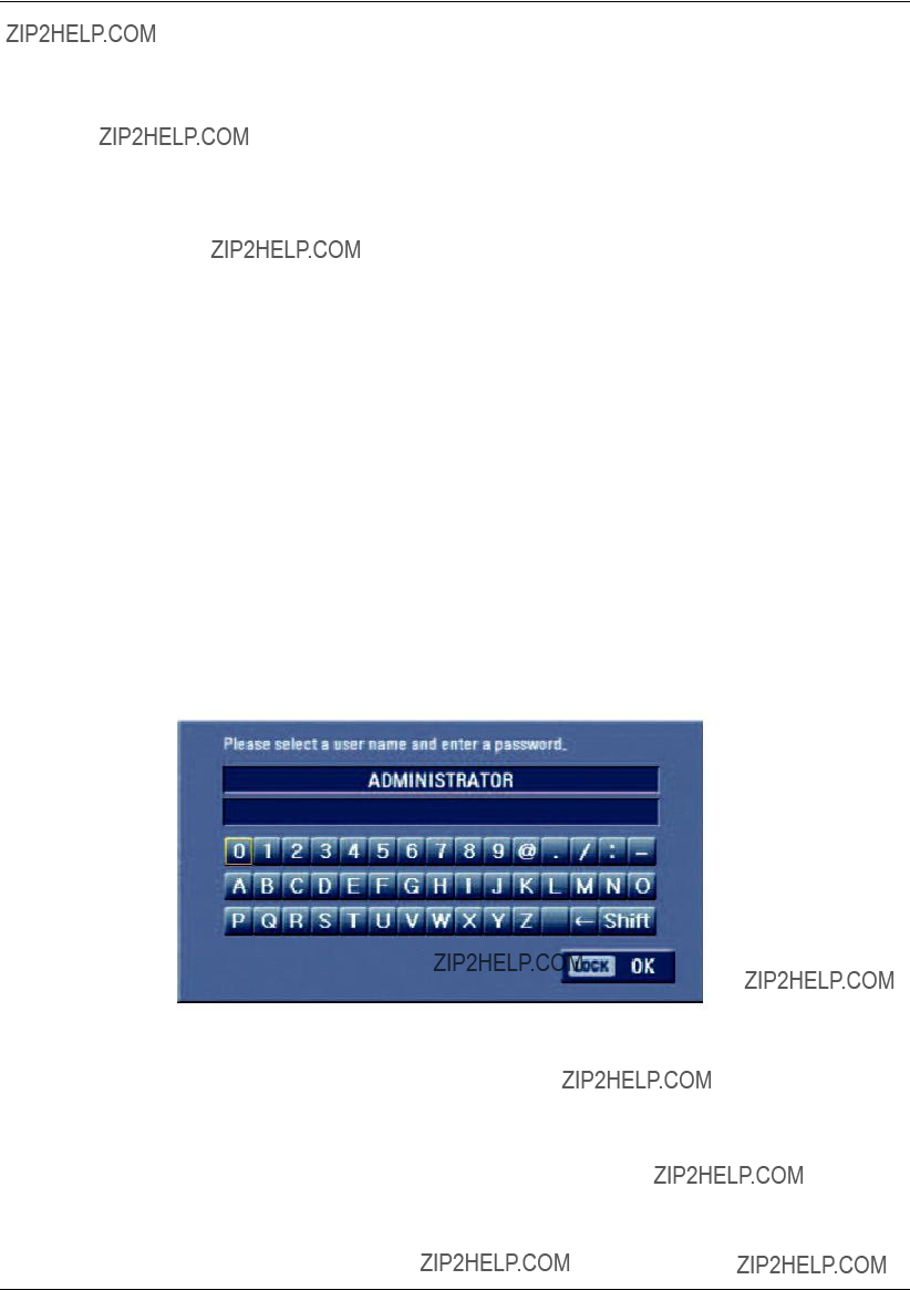
2.When booting is complete, the login window will be displayed.
Select a user ID by using the mouse or arrow, then the ENTER button on the remote control or front panel.
Figure 3.5 Login window
-ADMINISTRATOR: Unlimited operation of the unit.
-Advanced User: Use of the limited functions of the system (the setup con???guration is not allowed to change).
-Normal User: Use of the limited functions of the system (multiscreen monitor and live image view are available).
3.Enter the password by using the virtual keyboard. (Initial password is ???000000???.)
4.Press LOCK or click the OK (LOCK) icon.
You can see the live screen and operate the system.
???It is not possible to connect the VGA monitor and the composite monitor simultaneously. Consequently, the user is obliged to choose either the composite monitor or the VGA monitor. When set to composite monitor there is no VGA output. When set to VGA monitor there is no composite output. Monitor B is unaffected by the monitor setting.
???This DVR is based on a VGA monitor using OSD. We recommend using the VGA monitor with this unit. If you use a composite monitor, the OSD quality may lower to read it.
???User access rights:
3.12Selecting the main monitor type
You can select the main monitor type to display the main screen during power on.
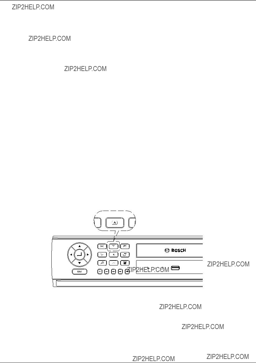
3.12.1Using the VGA monitor
1.Connect the VGA monitor to the VGA connector on the back of the DVR.
2.Turn on the VGA monitor.
3.Press and hold the A ( ) button on the front panel until the beep sounds to display the main screen. The DVR will restart and then the VGA monitor is set as a main monitor.
Figure 3.6 The A button on the front panel
3.12.2CCTV (composite video type) monitor
1.Connect the CCTV monitor to the MON A connector on the back of the DVR.
2.Turn on the CCTV monitor.
3.Press and hold the B ( ) button on the front panel until the beep sounds to display the main screen. The DVR will restart and the CCTV monitor is then set as main monitor.
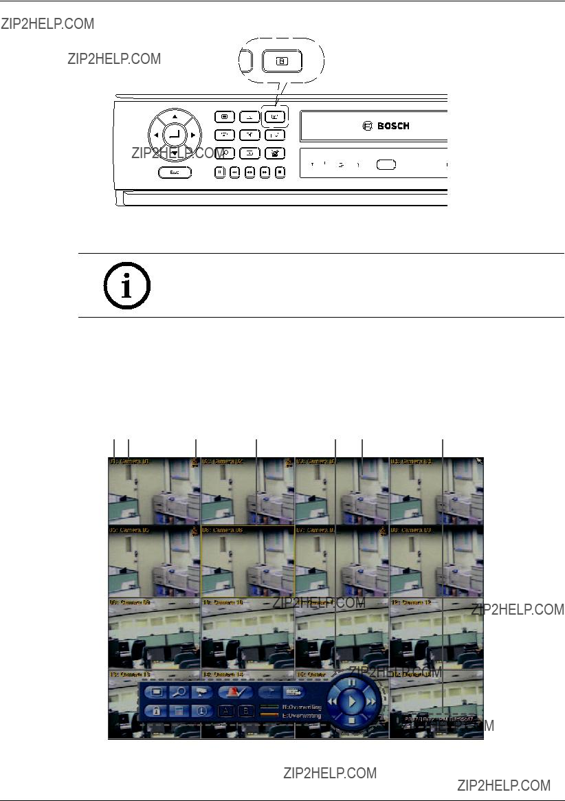
Figure 3.7 The B button on the front panel
Note:
You can select the monitor type by using the A ( ) or B (
 ) button at any time. If you change the monitor type, the system will be rebooted automatically.
3.13General explanation of the live screen on the main monitor
Main monitor screen
Figure 3.8 Main monitor screen

aChannel Number: Displays the channel number.
bCamera Name: Displays the edited camera name.
cRecording status icon: Displays the recording status.
???Red ???Dot icon??? indicates Instant recording.
???Yellow ???Running man icon??? indicates motion detection recording.
???Red ???Alarm bell icon??? indicates input triggered recording.
dSelected Channel: Displays the selected channel with yellow box.
eSystem Control Bar
??? : Displays the setup menu.
??? : Displays the search menu.
??? : Displays the PTZ remote control window.
??? : Displays the lock menu to change the user type or disable system operation.
??? : Displays the system log list window.
??? : Displays the system information window.
??? : Turns the alarm off.
??? : Displays the screen division selection window for the monitor A.
??? : Displays the screen division selection window for the monitor B.
??? : Click at a desired point to be marked during playback. Up to 15 points can be marked.
??? : Display copy (export) menu.
??? :Displays the remaining HDD status.
-N (Normal partition): Used size/total size.
-E (Event partition): Used size/total size.
??? : Pause playback.
??? : Select the required scanning speed.
??? : Starts instant playback in selected channel.
??? : Stop playback.
fLive Screen: Displays the current surveillance live screen.
gDisplays the current date and time.
Note:
Click the right button on the mouse to display / remove the system control bar displayed
3.14Selecting live screen mode
3.14.1Monitor A
You can select the live screen mode to display a full,
1.Press A ( ) button or click the
  icon in the system control bar. The screen mode select menu of monitor A is displayed on the monitor A.
2.Select screen mode.
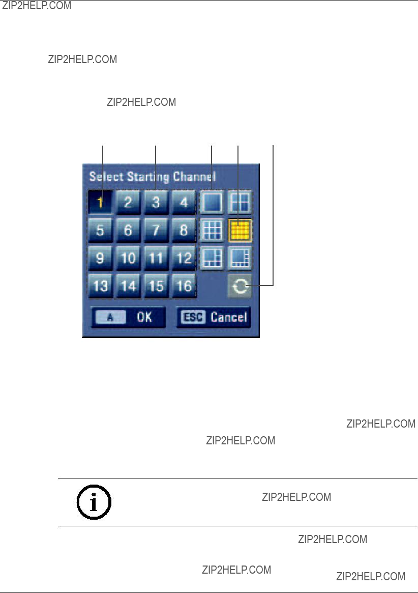
Figure 3.9 The screen mode select menu of monitor A.
a Selected channel of the monitor A.
b Channel buttons: Press the 1 to 16 channel button to see the current camera images in selected live screens on the monitor A.
c Screen mode
???Full Screen Mode: When you see the selected channel on the full screen.
???4, 6, 8, 9 and 16 view Mode: Displays selected multi screens on the monitor A. d Selected view mode.
e Sequence: Views the all channels in sequence.
3.Select [OK (A)] and press ENTER to con???rm your selection.
Note:
To display the screen you desire to watch in full screen mode, double click the desired channel.

3.14.2Monitor B
You can select the live screen mode to full or
1. Press B ( ) button or click the
  icon in the system control bar. The screen mode select menu of monitor B is displayed on the monitor A.
2.Select screen mode.
Figure 3.10 The screen mode select menu of monitor B.
a Selected channel of the monitor B.
b Channel buttons: Press a 1 to 16 channel button to see the current camera image on the monitor B.
c Screen mode
???Full Screen Mode: When you see the selected channel on the full screen.
???4 view Mode: Displays 4 view screens on the monitor B.
d Selected view mode.
e Sequence: View all channels in sequence.
3.Select [OK (B)] and press ENTER to con???rm your selection.
Note:
On Monitor B output always the channel number (CH01 ... CH16) is displayed. Camera name can only be displayed on Monitor A output.
3.15PTZ camera control
You can control the cameras connected via the biphase port and data port
1.Select the PTZ camera channel on monitor A you want to control.
2.Press PTZ or click the PTZ icon in the system control bar. PTZ virtual remote control is displayed on monitor A.
3.Use each item to control the PTZ camera.
a
b c
Figure 3.11 The PTZ virtual remote control.
3.15.1Preset settings
Preset position is the function to program camera monitoring positions (preset positions) associated with position numbers.
By entering the position numbers, you can move cameras to the preset positions.
Note:
To activate this function, you need to register the preset positions of the
PTZ camera.
3.15.2To program preset positions
1.Move the camera to a point you wish by using the v/V/b/B.
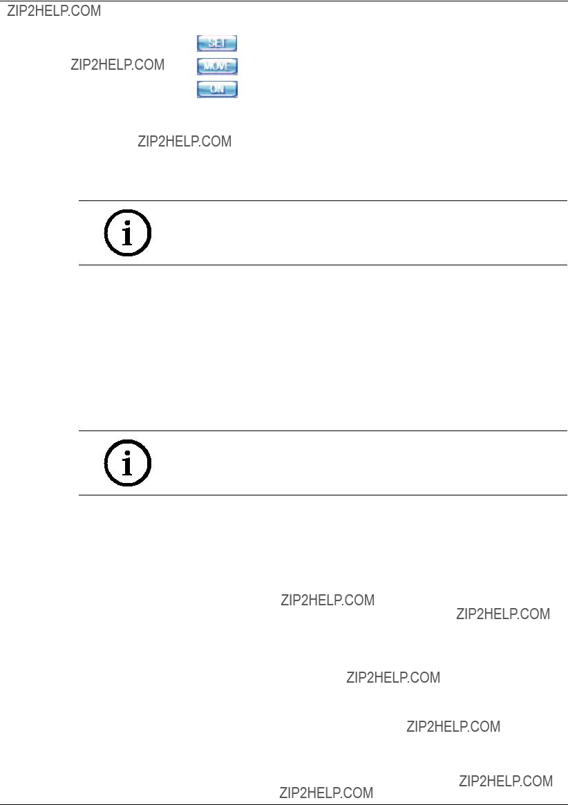
2.Press SET or click the [SET] icon.
3.Select the preset number you wish to register.
4.Press ENTER or click the  icon.
icon.
The position and its number are memorized.
5.Repeat steps
Note:
Preset numbers from 0 to 255 are available on this unit but the actual preset range differs depending on PTZ cameras.
3.15.3Changing to a preset position
The following function is available only with cameras provided with the preset function. The preset function makes the PTZ camera move to the programmed preset position. It is necessary to program preset positions for the PTZ camera beforehand.
1.Press the MOVE button or click the [MOVE] icon.
2.Use number buttons to enter the memorized preset position???s index number then press ENTER or click the  icon. The camera moves to the preset position and the picture of the camera in that position appears on the monitor.
3.15.4To clear the preset position
You can clear a memorized preset position.
1.Press the CLEAR button or Click the [CLEAR] icon.
2.Use number buttons to enter the memorized preset index number, then press ENTER or Click the  icon to clear the preset positions.
Note:
This function may not be available depending on PTZ cameras.
3.15.5To tour the preset positions
You can tour all preset positions.
1.Press the TOUR button or Click the [TOUR] icon.
All registered preset positions in the camera will be selected. The camera position image will be switched on the active monitor.
2.You can stop the tour by pressing the TOUR button or clicking the [TOUR] icon.
3.15.6Setup for PTZ cameras
You can adapt the camera to your requirements by setting up the respective items in menus.
1.Click the [SETUP] icon.
The setup menu appears in the selected window of the main monitor.
2.Use arrows, ZOOM +/- and ENTER buttons to set the options.
Notes:
???Refer to the manuals of the PTZ camera for more details.
???Some PTZ cameras may not operate correctly with this unit.
???You cannot control the other functions when the PTZ virtual remote con- trol is displayed.
???If you use the BOSCH PTZ camera that use the Bosch protocol, the SETUP icon is not displayed on the PTZ virtual remote control.
3.15.7To send the Aux On/Off commnd
1.Click the [ON] or [OFF] icon.
2.Enter the Aux command number of the BOSCH Auto Dome camera.
3.Click the  icon to send the Aux commend.
3.16Viewing System Information
To view system information:
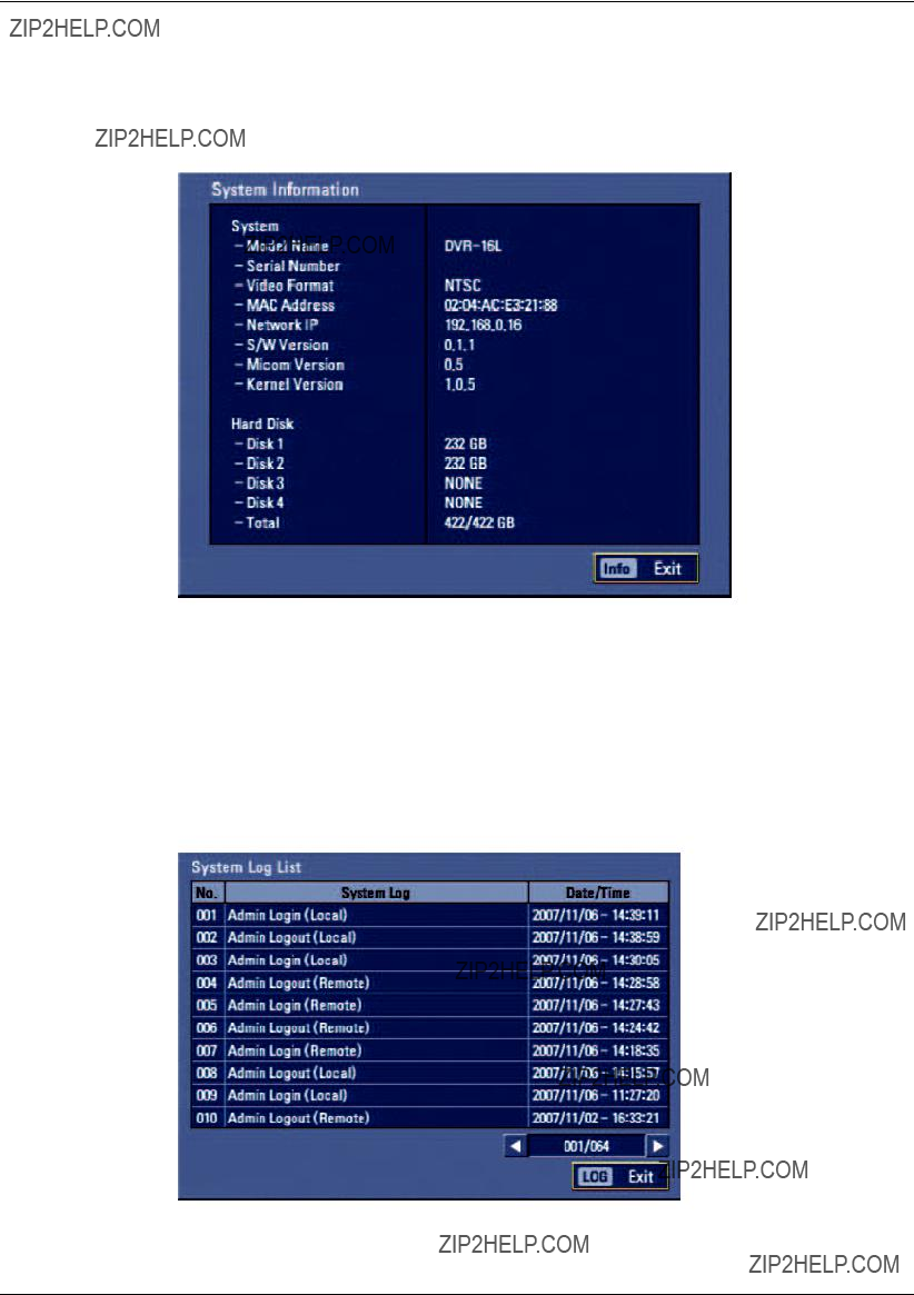
1.Press INFO or click the INFO icon in the system control bar. The system information window is displayed on the main monitor.
Figure 3.12 System information window
2. Press INFO or click the [Exit(Info)]button to exit the window.
3.17Viewing the System Log List
To view the system log list:
1.Press LOG or click the LOG icon in the system control bar. The system log list window is displayed on the main monitor.
Figure 3.13 System log window
2.Use b / B to see the previous or next log list.

3.Press LOG or click the [Exit(LOG)]button to exit the window.
??? The system log list:
Table 3.6 System log list

3.18Configuration Menu
The features and options of the DVR are configured through the menu. The operations of this unit can be set via a menu displayed on the main monitor. You can select and set the operational conditions by using the buttons on the front panel, the remote control, or using a USB Mouse connected to the unit.
Only
e f
Figure 3.14 DVR setup menu
aDisplays the selected main menu title.
bDisplays the main menu icons.
cDisplays the submenu options.
dDisplays the help menu.
eDisplays the selected submenu title.
fDisplays the detail options for selected submenu.
3.18.1Using a mouse to set a menu
Use the left and right mouse buttons to set the menu.
???Left button: Use to select a required item or decrease the options value.
???Right button: Use to increase the options value.
1.Click the  icon on the bottom of the
2.Click the desired menu icon with the left mouse button to display the submenu.
3.Click the desired submenu item with the left mouse button.
4.Set the selected options value.
5.Click the Exit icon to exit setup menu. If the save message appears, click [OK] with the left mouse button to save the settings.
3.18.2Setting the menu using the front panel buttons or remote control but- tons
???Arrow Buttons (v/V/b/B): Use these buttons to select the menu options or adjust the options value.
???ENTER: Select the option or con???rm the setting.
???ESC: Return to the previous menu or level.
1.Press SETUP( ) to display the setup menu.
2.Use b/B to select the desired menu icon.
3.Use v/V to select the desired submenu item, then press ENTER to display the setting options.
4.Use v/V/b/B to select the desired option, then press ENTER to set the value.
5.Use b/B to select the desired setting then press ENTER to con???rm your selection.
6.Press ESC to exit the Setup menu. If the Save message appears, press ENTER to save the settings.
Note:
When you operate the function menu by using the remote control and front panel buttons, both buttons are operated in the same way to control the function menu.
To use other functions of number buttons on the front panel as shown below:
1.Press ALT. The button indicator turns green.
2.Select the function button you want.
All the operation explanations are based on using the remote control.

3.19Camera settings
3.19.1Camera
The camera name, covert and input audio channel settings are configured.
Figure 3.15 Camera setup menu
???Ch: Displays the channel number.
???Name: Enter the camera name using up to 12 characters.
-b/B/v/V: Select a character.
-ENTER: Con???rms your selection.
-ESC: Exits the virtual keyboard menu.
???Covert: You can set the camera conditions to prevent operation by other users.
???Audio: You can hear from the selected input audio channel.

3.19.2Video adjustment
Adjust the brightness, contrast and color settings of each camera channel. You can see the settings screen from the preview windows.
Figure 3.16 Video adjustment setup menu
???Channel: Selects the desired channel to adjust.
???Brightness: Adjust the brightness value from 00 to 100 for the selected channel.
???Contrast: Adjust the contrast value from 00 to 100 for the selected channel.
???Color: Adjust the color value from 00 to 100 for the selected channel.
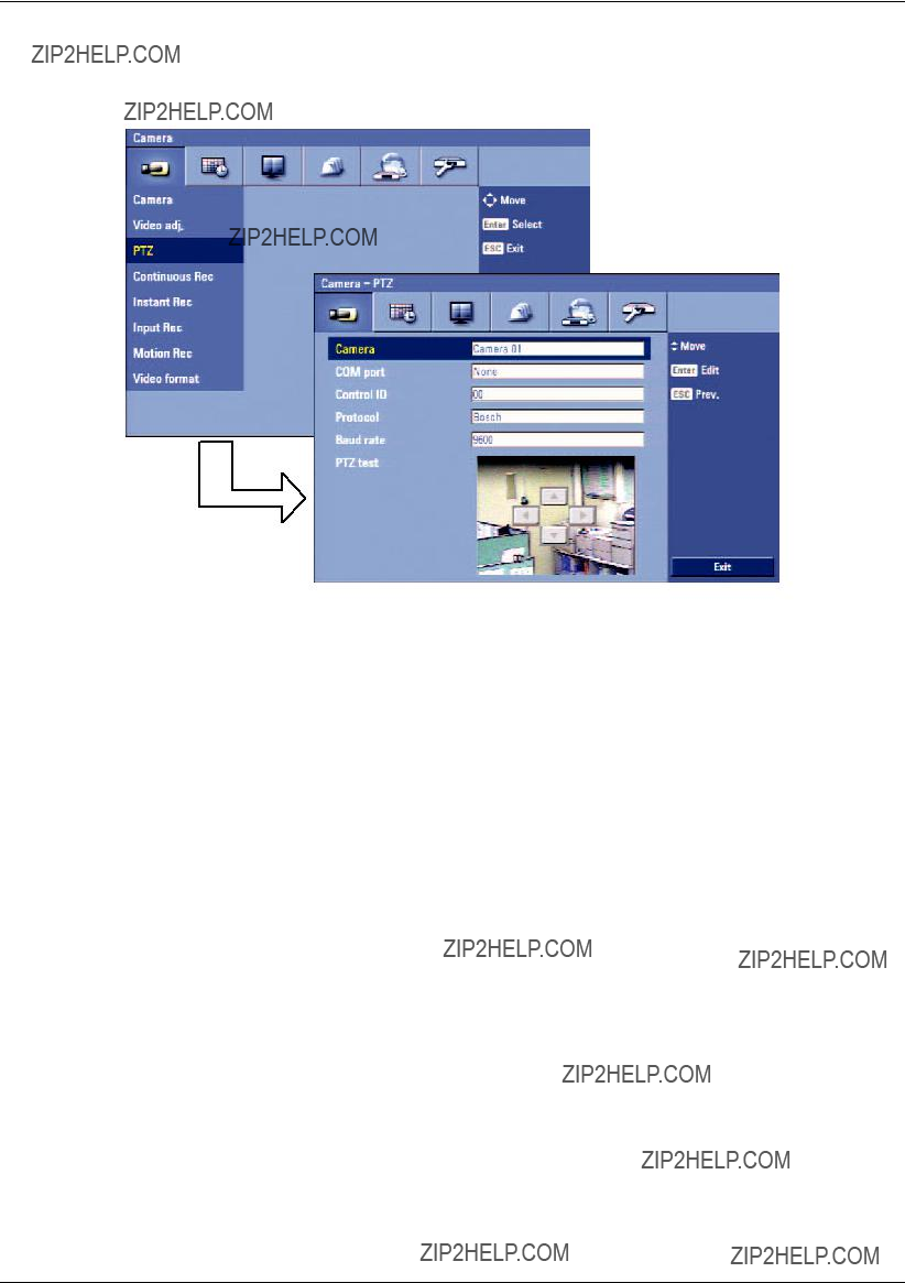
3.19.3PTZ
Settings for the PTZ cameras connected via the data port of the biphase connecter or
Figure 3.17 PTZ setup menu.
???Camera: Selects the desired camera to set the connected PTZ camera.
???COM port: Selects the connected data port of the biphase connecter, or
???Control ID: Selects the PTZ camera ID from 00 to 255. Make the same settings as the PTZ camera.
???Protocol: Selects the protocol supported by PTZ camera.
???Baud rate: Selects the communication speed (1200, 2400,4800,9600,19200 or 38400).
???PTZ test: After the PTZ setting, you can test the pan/tilt function for the selected PTZ camera. You can see the test screen from the preview windows on the right side of the PTZ test option.
-b/B: Test the pan direction.
-v/V: Test the tilt direction.
3.19.4Continuous recording
Settings concerning continues recording.
Figure 3.18 Continuous recording setup menu
???Ch: Displays the channel number.
???Resolution: Selects the recording resolution.
???Quality: Selects the recording picture quality (Lowest, Low, Normal, High or Best).
???Frame rate: Selects the frame rate. The frame rate is the number of recorded frames per second. According to resolution, the frame rate is set automatically. If you wish to set manually, refer to the below table.
Table 3.7 Frame rate table
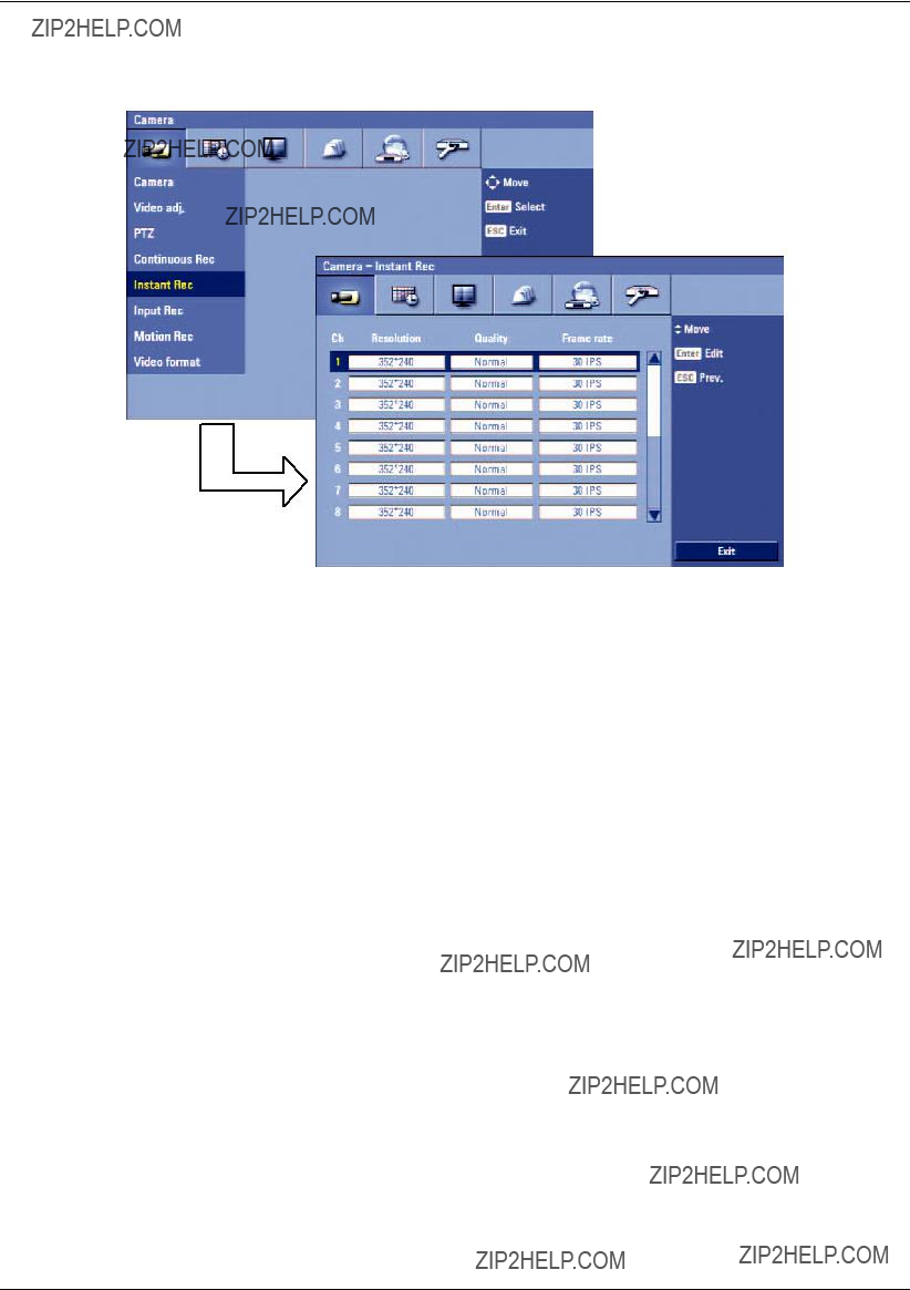
3.19.5Instant recording
Settings concerning instant recording.
Figure 3.19 Instant recording setup menu
???Ch: Displays the channel number.
???Resolution: Selects the recording resolution.
???Quality: Selects the recording picture quality (Lowest, Low, Normal, High or Best).
???Frame rate: Selects the frame rate. The frame rate is the number of recorded frames per second. According to resolution, the frame rate is set automatically. If you wish to set manually, refer to the below table.
Table 3.8 Frame rate table
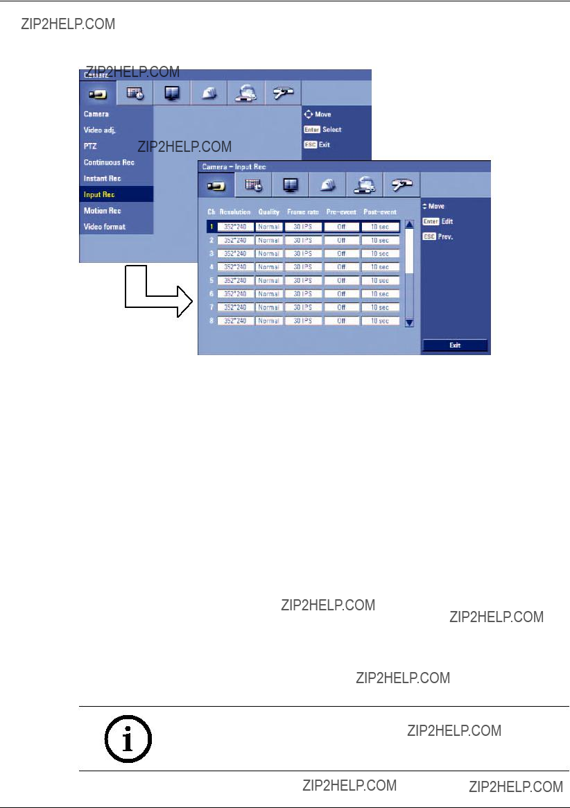
3.19.6Input recording
Settings concerning input recording.
Figure 3.20 Input recording setup menu
???Ch: Displays the channel number.
???Resolution: Selects the recording resolution.
???Quality: Selects the recording picture quality (Lowest, Low, Normal, High or Best).
???Frame rate: Selects the frame rate. The frame rate is the number of recorded frames per second. According to resolution, the frame rate is set automatically. If you wish to set manually, refer to the below table.
Table 3.9 Frame rate table
???
???
Note:
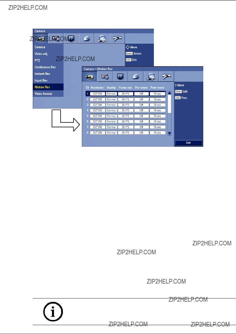
3.19.7Motion recording
Settings concerning motion recording.
Figure 3.21 Motion recording setup menu
???Ch: Displays the channel number.
???Resolution: Selects the recording resolution.
???Quality: Selects the recording picture quality (Lowest, Low, Normal, High or Best).
???Frame rate: Selects the frame rate. The frame rate is the number of recorded frames per second. According to resolution, the frame rate is set automatically. If you wish to set manually, refer to the below table.
Table 3.10 Frame rate table
???
???
Note:
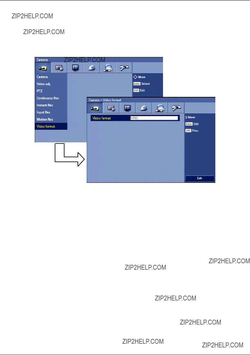
3.19.8Video format
Selects the video format to NTSC or PAL according to your video system format.
1.Select the video format.
The con???rmation message is displayed.
2.Select [OK] and press ENTER.
After the HDD has been formatted, the system will reboot.
Figure 3.22 Video format setup menu
3.20Schedule settings
The DVR can record according to a schedule set by the user. It can also record manually regardless of date and time. The recording can be made either continuously or triggered by events (input and motion detection).
The recording schedule screen displays one day of the week showing the schedule of all channels over a
For each

Figure 3.23 Schedule setup menu
3.20.1To set the Recording Schedule for a typical day of the week
1.Select a day of the week. (Sun, Mon, Tue, Wed, Thu, Fri or Sat)
2.Select the desired channel to schedule recording.
3.Select the time cell block for the start time.
Figure 3.24 Schedule setup menu
4.Press ENTER or click the left mouse button to select a recording mode. The color of the cell blocks will change automatically.
-Gray: No scheduled recording
-Blue (Continuous recording): Recording starts automatically from the preset time.
-Red (Input event recording): Recording starts automatically when the input is activated within a designated time.
-Yellow (Motion event recording): Recording starts automatically when motion is detected within a designated time.

-Green (Input+Motion recording): Recording starts automatically when the input is activated or motion has been detected.
-Blue+Red (Continuous+Input event recording): Recording starts automatically from the preset time. When the input is activated within a designated time, change the continuous recording mode to input event recording mode and recording starts automatically.
-Blue+Yellow (Continuous+Motion event recording): Recording starts automatically from the preset time. When the motion is detected within a designated time, change the continuous recording mode to motion event recording mode and recording starts automatically.
-Blue+Green (Continuous+Input+Motion event recording): Recording starts automatically from the preset time. When the input is activated or motion has been detected, change the continuous recording mode to motion event recording mode and recording starts automatically.
5.Select the next time cell block of schedule time cell blocks to con???rm the schedule time.
Figure 3.25 Schedule setup menu
6.Press ENTER or click the left mouse button repeatedly to select gray to set the time for the end of the schedule. The settings cell block is highlighted.
Figure 3.26 Schedule setup menu
7.Press MENU to con???rm your settings. The con???rmation window is displayed.
8.Select OK and press ENTER to save the new settings.
??? Press ESC to exit the speci???c date selection menu.
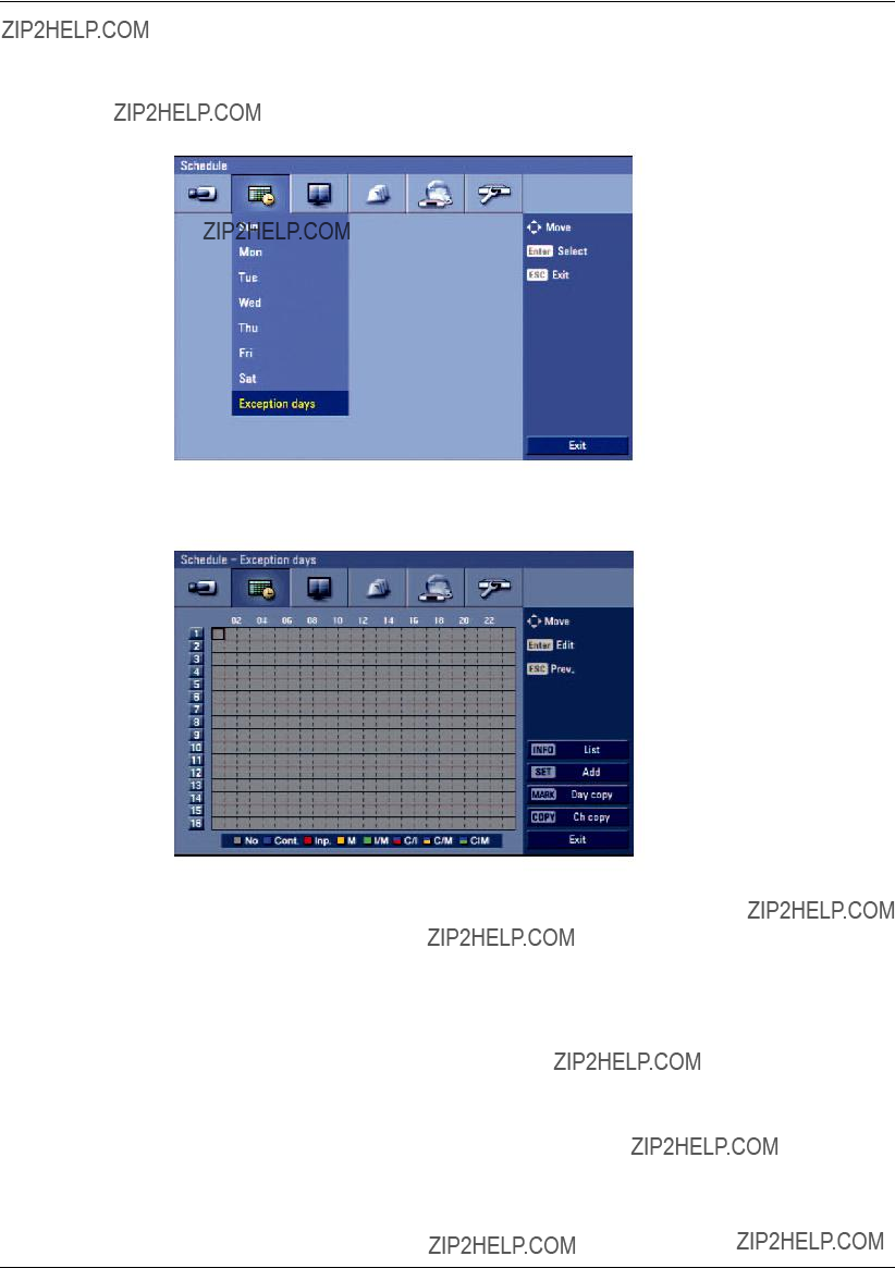
3.20.2To set a recording schedule for an Exception days
In addition to the weekly schedule, up to 10 specific date/time periods can be defined. To configure the specific recording schedule select Specific Dates.
1.Select the [Exception days] option.
Figure 3.27 Exception days setup menu
2.Select a cell block.
Figure 3.28 Exception days setup menu
3.Press the SET button or click the  icon on the exception days setting menu. The speci???c date selection menu appears.

Figure 3.29 Exception days setup menu
4.Enter the necessary information for year, month and date.
???b/B/v/V: Press to move the columns, [OK] or [Cancel] buttons.
???b/B (or left/right mouse button): Changes the value at the current position.
5.Use b/B/v/V to select [OK] button and press ENTER. The virtual keyboard menu appears.
Figure 3.30 Exception days setup menu
6.Enter the name of the exception day. Use v/V/b/B to select a character then press ENTER to con???rm your selection.
7.Use v / V to select the [OK] icon then press ENTER to ???x the date of the special day and return to the special day menu screen.
8.Select the schedule time and set the recording method for each channel.
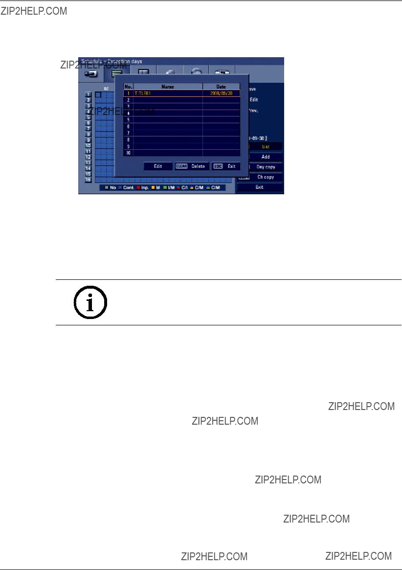
3.20.3Checking the Exception days schedule list
1.Press INFO when the ???Exception days??? option is selected. The exception days scheduled list appears.
Figure 3.31 Exception days scheduled list
2.Select a exception day title on the list and press ENTER. The title color turns orange.
3.Select the [Edit] icon, press ENTER to edit the exception day or press CLEAR to delete the exception day schedule.
4.Press ESC to exit the exception day schedule list.
Note:
If the exception day recording schedule is duplicated with the other recordings, only the exception day recording is possible.
3.20.4Copying the recording schedule
Copying from the scheduled data of the channel
You can copy the schedule data of the channel to the other channel(s) within the selected day of the week.
1.Select the day of the week and press ENTER.
2.Select channel that you want to copy.
3.Press COPY then the channel selection menu appears.
Figure 3.32 Channel copy menu
4.Use b/B to move to the left or right column then press ENTER to select the target channel(s). You can cancel the selected channel by pressing ENTER.
5.Use v/V to select [OK] then press ENTER to con???rm your selection.
Copying from the Scheduled Data of the day
You can copy the scheduled day of the week to another day of the week, weekday and weekend using the MARK button.
1.Select the day of week that you want to copy.
2.Press MARK then the select date(s) menu appears.
Figure 3.33 Day copy menu
3.Use b/B to select the target date(s).
4.Use v/V to select [OK] then press ENTER to confirm your selection.
3.21Display settings
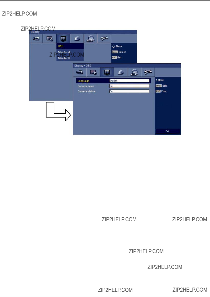
3.21.1OSD
Figure 3.34 OSD setup menu
???Language: Select a language for the setup menu and information display.
???Camera name
-On: Displays the title of the camera.
-Off: Displays the live picture without the title of the camera.
???Camera status
-On: The current camera recording status is displayed.
-Off: Remove the current camera recording status.
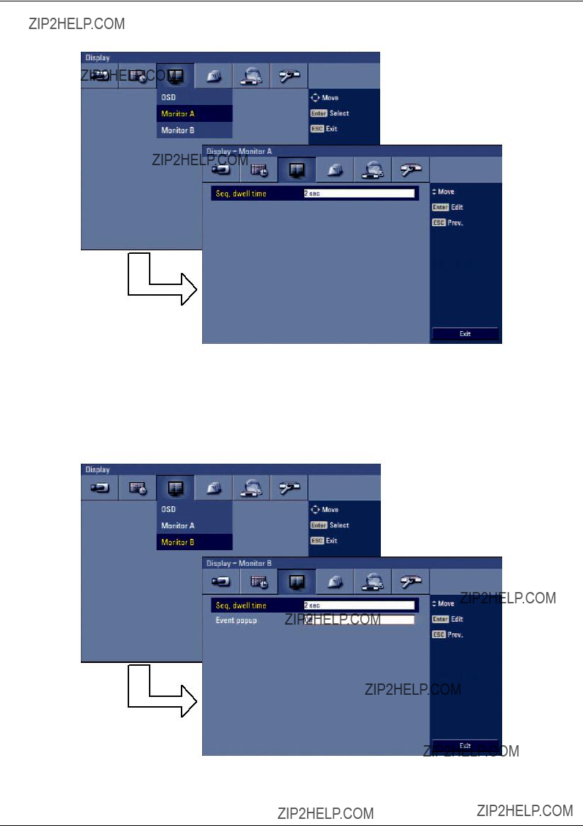
3.21.2Monitor A
Figure 3.35 Monitor A setup menu
???Seq. dwell time: You can set the camera sequence time to 2 sec, 5 sec, 10 sec, 20 sec, 30 sec, 40 sec, 50 sec, 60 sec, 70 sec, 80 sec or 90 sec.
3.21.3Monitor B
Figure 3.36 Monitor B setup menu

???Seq. dwell time: You can set the camera sequence time to 2 sec, 5 sec, 10 sec, 20 sec, 30 sec, 40 sec, 50 sec, 60 sec, 70 sec, 80 sec or 90 sec.
???Event popup: Displays an event popup on the monitor B if motion, input or all (motion or input) occur.
3.22Event settings
3.22.1Input
Figure 3.37 Input setup menu
???In: Displays the number of inputs.
???Input type: The input state can be set to either N.O. (Normally Open) or N.C. (Normally Closed).
???Camera: Select the connected camera channel to the input.
???Relay output: Select the relay output number for the selected input.
???Preset: Select the preset number. When the input is activated, the camera moves to the selected preset position and the picture of the camera in that position appears on the monitor.

3.22.2Motion
Figure 3.38 Motion setup menu
???Camera: Select the camera to set motion detection.
???Sensitivity: Set the level of sensitivity for the created motion detection area. Sensitivity can be set from level 01 to 10 or Off.
???Relay output: Select the number of the output relay when motion is detected.
???Area: Select the desired motion detection area on the preview window screen.
-b / B / v / V: Moves the yellow cell box to another cell zone.
-ENTER: Selects or cancels the motion detection area at the current cell position.
-Press ESC to exit the settings.
???You can select the motion detection area by using the mouse.
-To select the area: Drag & drop a cell to the right to select the motion detection area.
-To cancel area: Drag & drop a cell point of a selected cell area to the left to cancel the motion detection area.
Note:
In situations where illumination is low and the outline of object is not clear enough to see, regardless of sensitivity, Motion Event might not activate. You must check Motion Event before setting.
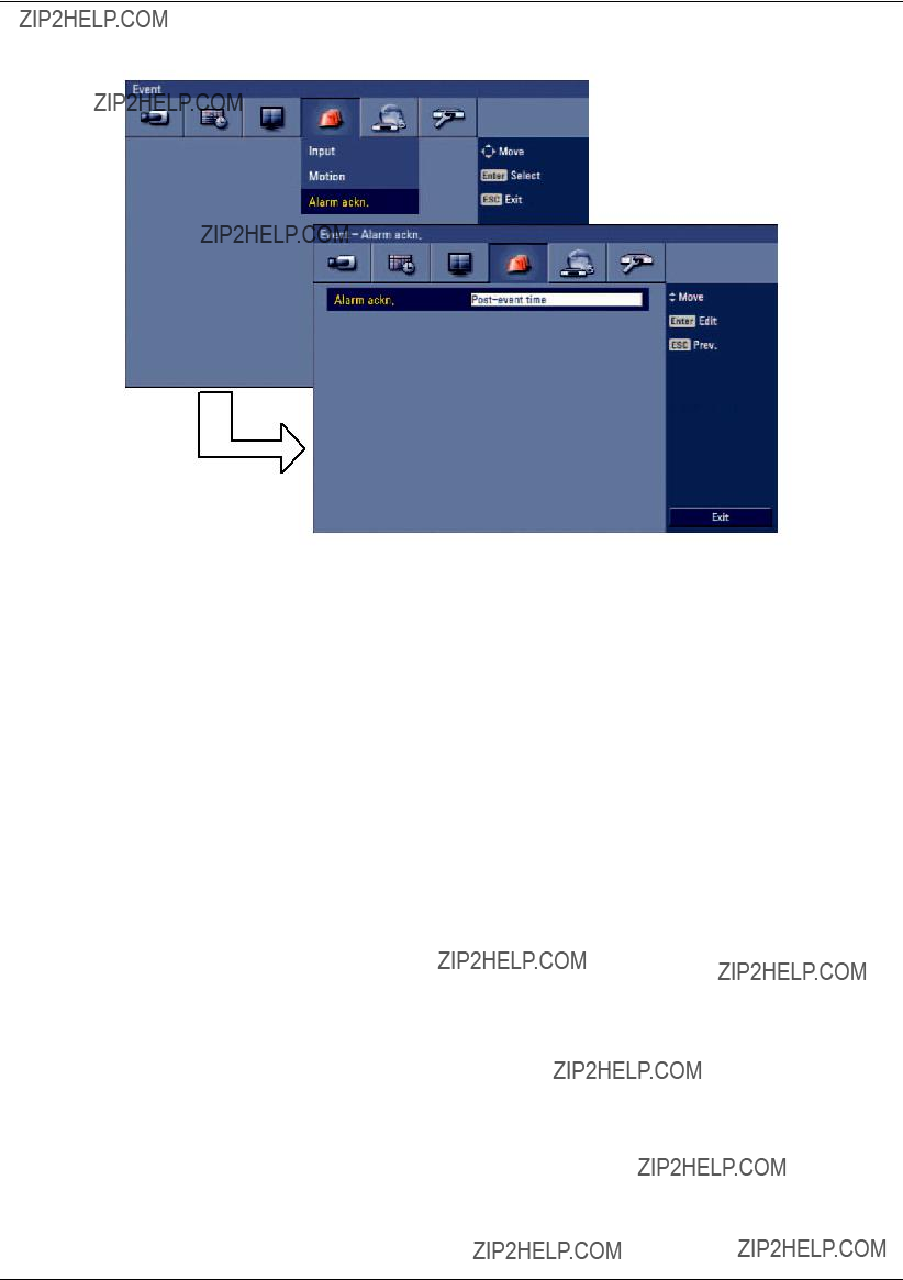
3.22.3Alarm acknowledgement
Figure 3.39 Alarm acknowledgement setup menu
???Alarm ackn.
-Manual: Use the ACK button on the remote control or  button on the front panel to stop alarm.
-

3.23Network settings
3.23.1TCP/IP
Figure 3.40 TCP/IP setup menu
???DHCP: DHCP stands for Dynamic Host Con???guration Protocol.
-On: Network settings of this unit are con???gured automatically by the DHCP server. If you set to ON, the [IP Address], [Subnet Mask], [Gateway], [Primary DNS] and [Secondary DNS] options are dimmed and these options can not be set.
-Off: Enter the network settings manually.
???IP address: Enter an IP address using the virtual keyboard.
???Subnet mask: Enter a subnet mask address using the virtual keyboard.
???Gateway: Enter the gateway address using the virtual keyboard.
???Primary DNS: Enter the Main DNS server address using the virtual keyboard.
???Secondary DNS: Enter the Sub DNS server address using the virtual keyboard.
???Remote client port no.: Enter the remote client port number using the virtual keyboard. You can watch the live surveillance image over the network with the Control Center program. The factory default port for transmission of video and audio data is 9001. However in some cases it is better to change this port number for added ???exibility or security. If desired change the port number (1025 ~ 65535).
???HTTP port no.: Enter the HTTP port number using the virtual keyboard. You can watch the live surveillance image over the network with a web browser. Typically the TCP port used by HTTP is 80. However in some cases it is better to change this port number for added ???exibility or security. If desired change the port number (80 or 1025~ 65535).
???Bandwidth limit: Enter the Bandwidth to adjust the data traf???c.
Note:
When you change the Remote client port or HTTP port number, all connections with the Control Center programs or web browser will be disconnected.

3.23.2DDNS (Dynamic Domain Name System)
Figure 3.41 DDNS setup menu
???User name: Enter the DDNS registered user name using the virtual keyboard.
???Password: Enter the user password in [User name] using the virtual keyboard.
Note:
The DDNS function is serviced using a TCP 8245 port by
In case the DVR is used in the network system with a firewall, open the TCP 8245 port so that DDNS data can get into firewall. For more detail on firewall setup, ask your network administrator and/or network service provider.

3.23.3Notification
Figure 3.42 Notification setup menu
???Alarm on:
-On: Sends an
-Off: Not used.
???Motion detect:
-On: Sends an
-Off: Not used.
???Disk full:
-On: Sends an
-Off: Not used.
???Admin PW changed:
-On: Sends an
-Off: Not used.
???Video loss:
-On: Sends an
-Off: Not used.
???Power on/off:
-On: Sends an
-Off: Not used.
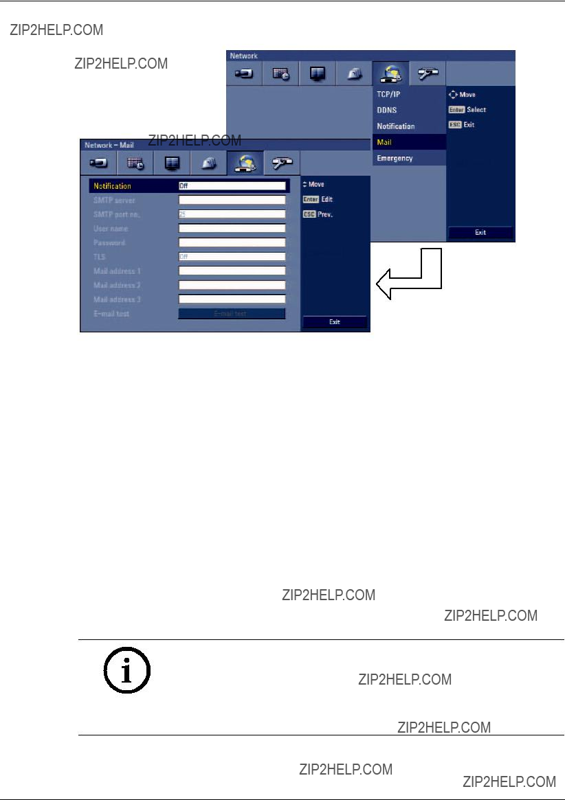
3.23.4Mail
Figure 3.43 Mail setup menu
???Noti???cation
-On: Noti???es the user by
-Off: The noti???cation function is not used. The mail options are dimmed.
???SMTP server: Enter the SMTP Server address using the virtual keyboard.
If noti???cation is set to On and the SMTP server option is empty, the SMTP port no., user name, and password options are dimmed and the options are not set.
???SMTP port no.: Enter the SMTP port number using the virtual keyboard. Typically the port used for SMTP is 25. However, in some cases it is better to change this port number for added ???exibility or security. If desired change the port number (1 ~ 65535).
???User name: Enter the user name using the virtual keyboard.
???Password: Enter the password using the virtual keyboard.
???TLS: Set to On when using the TLS (Transport Layer Security) function. By default, TLS is Off.
???Mail address
???
Note:
The SMTP server, SMTP port no., user name or password settings are optional. The DVR can send
3.23.5Emergency
Figure 3.44 Emergency setup menu
???Noti???cation:
-On: Noti???es the Alarm noti???er program about unit operating information according to your noti???cation settings.
-Off: Noti???cation function is not used.
???IP address/Port no.: Enter the IP address/port number of the Alarm noti???er program using the virtual keyboard. The factory default port for this function is 9002. However, in some cases it is better to change this port number for added ???exibility or security. If desired, change the port number (1025 ~ 65535). You can set up to 9 IP address/port numbers.
3.24System settings
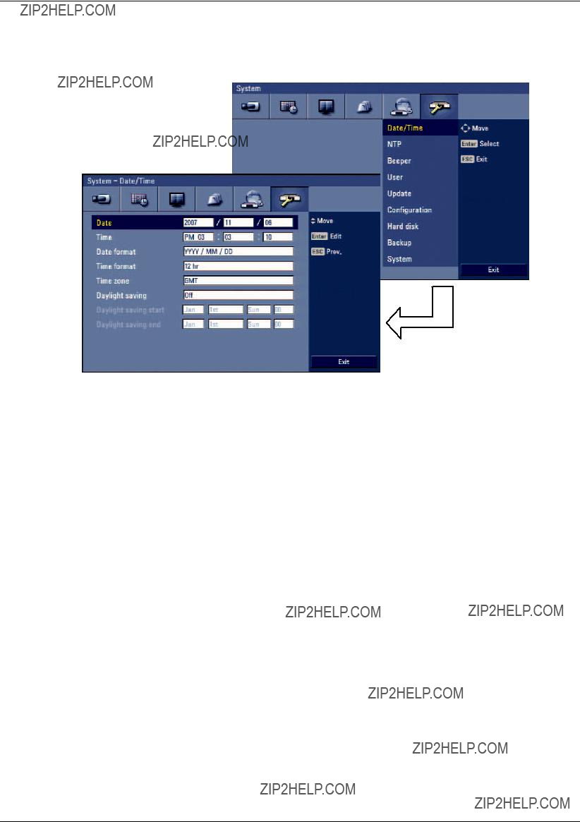
3.24.1Date/Time
Figure 3.45 Date/Time setup menu
???Date: Enter the current date.
???Time: Enter the current time. (24 HR or 12 HR)
???Date format: Select the date display format.
???Time format: Select the time display format.
???Time zone: Select your Time zone (for more details see "8.3 Time zones").
???Daylight saving: Set to On to use the daylight saving function.
???Daylight saving start: Select the Daylight saving start time.
???Daylight saving end: Select the Daylight saving end time.

3.24.2NTP
Figure 3.46 NTP setup menu
???NTP: Set to On when using the NTP (Network Time Protocol) server for time adjustment. If the NTP is set to Off, the time settings should be entered manually and the [Time server], [Private time server], [Sync. interval] and [NTP test] options are deactivated.
???Time server: For most cases select public. The DVR will obtain the average time among 5 public servers (time.nist.gov,
???Private time server: Enter the private time server???s IP address or host name using the virtual keyboard.
???Sync. interval: You can set synchronized intervals with the NTP time server to 1 day, 1 hour, 1 month and 1 week.
???NTP test: Select [NTP test] to test the NTP server.

3.24.3Beeper
Figure 3.47 Beeper setup menu
???Button beeper
-On: Makes a sound when using the buttons.
-Off: Turns off the button beep.
???Input beeper
-On: Makes a sound when a input is activated.
-Off: Turns off the input beeper.
???Motion beeper
-On: Makes a sound when a motion is detected.
-Off: Turns off the motion beeper.
???System beeper
-On: Makes a sound when a cooling fan is not activated or the HDD has a bad sector.
-Off: Turns off the system beeper.
Note:
The beeper is a low sound on this unit. If you want to make a loud sound, connect an external alarming device to the output connecter (ext. siren).

3.24.4User
You can register a new user with various access rights to the DVR or Control Center.
Figure 3.48 User setup menu
???No.: Displays the user number.
???ID: Enter the new user ID using the virtual keyboard.
???Level: Select the level of the new user.
???Password: Enter or change the password for the user using the virtual keyboard. You can use the password with number, special character or characters. (minimum length 4, maximum length 8).
Note:
Remember the password. If you forget the password please contact an authorized service center or the dealer you purchased the system.
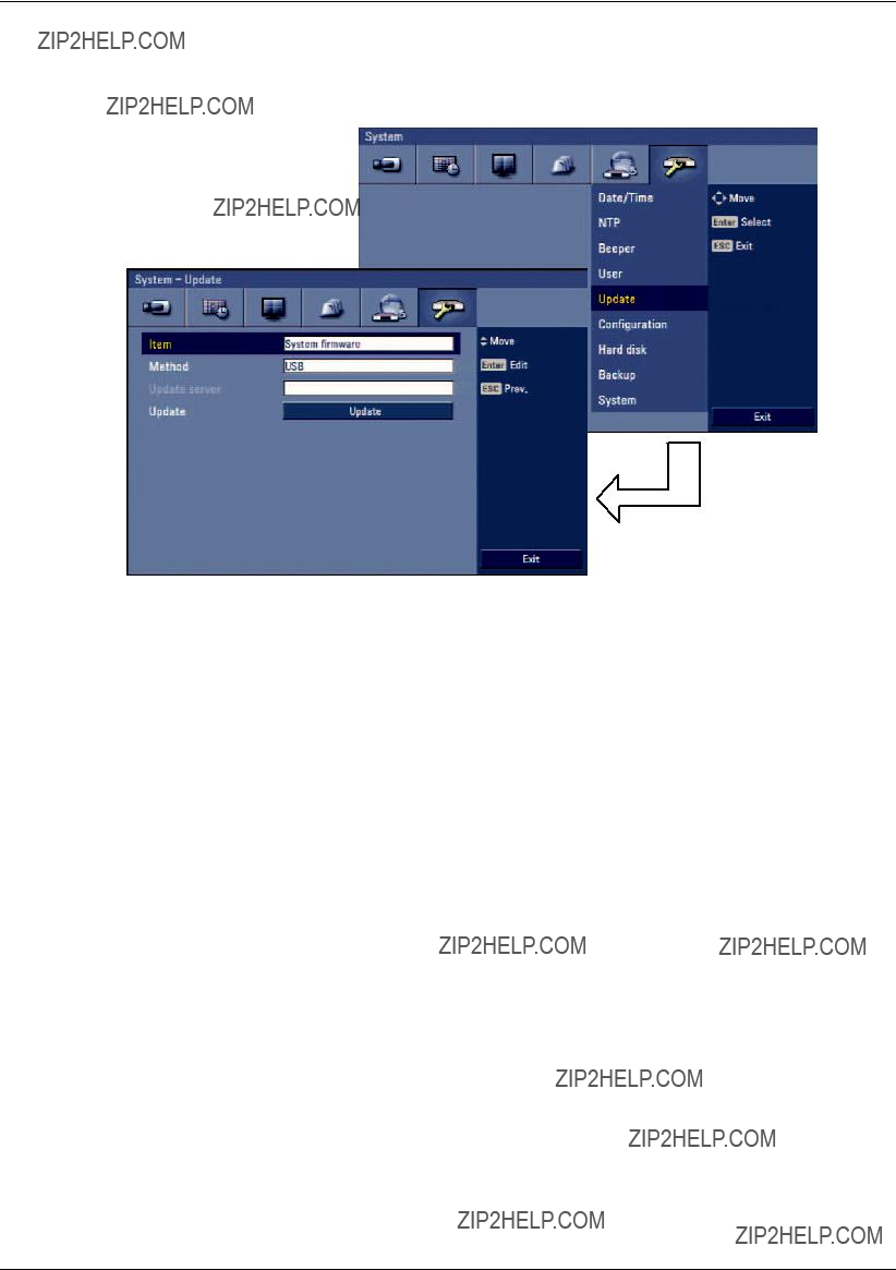
3.24.5Update
The update feature allows you to upgrade DVR software and add/upgrade PTZ protocols. In this case, the current DVR settings are not deleted or replaced during the update process.
Figure 3.49 Update setup menu
1.Select one of the following:
???Select System ???rmware to upgrade DVR system software.
???Select PTZ protocol to update the DVR protocols.
2.Choose the media from which to perform the update:
???USB: Select USB, and then insert the USB drive into the DVR. All USB devices must be disconnected before you can use the USB drive.
???Network: Select Network, and then do the following:
a.Select the update server settings box. The virtual keyboard is displayed.
b.Enter the update server IP address. The DVR network settings must be con???gured and you must know the update server???s IP address.
3.Select Update to start the update process.
4.Select OK to begin the update process or click Cancel to stop and exit. After the update process is completed, the system displays the Restart the system dialog box.
5.Click OK to restart the DVR.
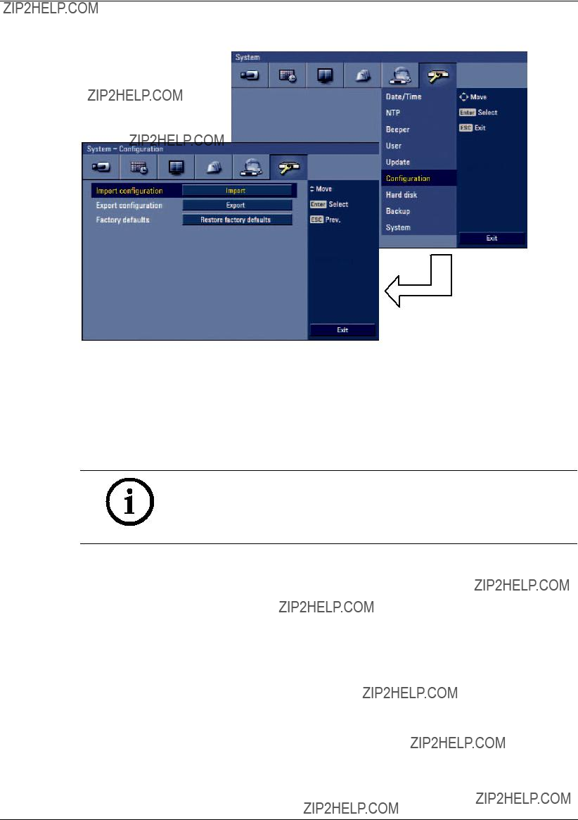
3.24.6Configuration
Figure 3.50 Configuration setup menu
???Import con???guration: Import the DVRs con???guration data from the USB memory stick.
???Export con???guration: Export the con???guration data from this DVR to the USB memory stick.
???Factory defaults: You can reset the DVR to its original factory settings. Some options cannot be reset (Video format, Date, Time, Time zone, Daylight saving, Daylight saving start, Daylight saving end, User settings, Event partition settings).
Notes:
???Configuration data import is available when the configuration data of a DVR is the same kind as this unit???s data.
???If you use a USB memory stick for configuration export, you must dis- connect the other external USB devices.

3.24.7Hard disk
Figure 3.51 Hard disk setup menu
???Overwrite:
-All: Overwrite recording is possible when the normal partition and event partition of HDD have fully recorded.
-Normal partition: Overwrite recording is possible for normal partition of HDD when the normal partition of HDD has fully recorded.
-Event partition: Overwrite recording is possible for event partition of HDD when the event partition of HDD has fully recorded.
-Off: Do not use overwriting.
???Disk full warning: When the HDD has over???owed a warning message is displayed.
???Event partition: Set the space of event partition for event recording.
???Auto delete: Set the auto delete date (Off, 1 day, 2 days, 5 days, 7 days, 10 days, 20 days, 30 days, 40 days, 50 days or 60 days). If you set the auto delete date, the recorded data will be deleted except the data within the selected date period of time. The Auto delete function is activated every 35 minutes.
???Format: Initializes the HDD (Hard Disk Drive). All data on the selected HDD will be erased. To format HDD(s) enter YES (all capitals) for all language settings.
Notes:
If you change the value of event partition, the current recorded data of HDD is deleted and the partition is reset. The partitions will be formatted automatically and the system will be restarted.

3.24.8Backup
Figure 3.52 Backup setup menu
???Partition selection: Select a backup partition.
???Schedule: You can set the backup schedule.
-Off: All options are disabled.
-Instant: The backup data is saved manually.
-Weekly or daily: The backup data will be automatically saved according to the setting.
???Device: Select a backup device.
???Schedule start: Set the schedule start date (a day of the week and time).
???Time range date: Enter the backup time range. Enter the date you want to backup.
???Time range start: Enter the start day of the week or time.
???Time range end: Enter the end day of the week or time.
???Estimate size: Displays the size of backup data and the free space of external devices.
???Start backup: To start backup.
???Erase media: To erase the media.

Notes:
???The backup function is not supported on the external USB
???Backup to external USB HDD is supported with maximum 250 GB.
???Use the recommended external USB devices for preventing malfunction (See ???8.2.1 Supported USB memory list???).
???The
???An external media has to be formatted on this unit to prevent malfunc- tion.
???DVD+RW and
???You cannot use the [Estimate size], [Start backup] and [Erase media] options in backup progressing.
???Do not remove the USB device while the backup is in progress, it may cause a malfunction. If you reuse the removed device, you must format the media by using Erase media options.
???If you format the external media by using a PC with FAT32, the media may not be used on this unit.
Instant Backup
1.Connect the backup USB device or insert a recordable disk to the disc driver for backup.
2.Select the partition you want to backup.
3.Select INSTANT from the schedule options.
4.Select the backup device.
5.Select the Time range date, Time range start time, and Time range end time for backup.
6.Select the [Estimate size] icon and press ENTER.
7.Check the size of the selected data and free space. If the device does not have enough space, create space on the device or erase the previously stored data.
8.Select the [Start backup] icon and press ENTER to start backup.
9.Exit the setup menu.
You can check the backup status on the system control bar in backup progress.
Note:
You cannot stop the backup while in progress.
???The warning message will appear for the conditions listed below.
-When the start time and end time are the same value.
-When the start time is later than the end time.
-A media does not have enough space.
-When you set the time for data that does not exist.
???The disc burning is carried out by a single session closed format.
???If you use the CD/DVD writer device for backup,the backup status will be displayed as shown below.
-1st. Status of making ISO image
-2nd. Status of writing
Daily/Weekly backup
1.Connect the USB device for backup.
You cannot use the CD or DVD writer for daily or weekly backup.
2.Select Weekly or Daily on the schedule options.
3.Select the backup device.
4.Enter the date and/or time to start backup on the schedule start option.
5.Enter the day of week and/or time on the Time Range Start option.
6.Enter the day of week and/or time on the Time Range End option.
7.Select [Estimation size] icon and press ENTER.
8.Check the size of selected data and free space of USB device. If the USB device does not have enough space, change the USB device of enough space or erase the connected USB device.
Note:
You cannot stop the backup while in progress.
???The warning message will appear for the conditions listed below.
-When the start time and end time setting are wrong.
-A media does not have enough space.
-When you set the time for data that does not exist.
-When the selected USB device is disconnected.
???The estimated size of backup data is only the approximate size. Be sure to allocate suf???cient space on the media to accommodate the backup task.
???You can check the backup status on the system control bar.
???The scheduled backup will not start if there is an export or a search of the external USB device in progress. After the export or backup search is ???nished, scheduled backup will be restarted.
???When you set the schedule backup, the backup data size is estimated from the recording settings of the Setup menu. If the actual recorded data size is larger than the estimated recording data size, the schedule backup may not be activated.

3.24.9System
Figure 3.53 System setup menu
???IR remote controller: Select the IR remote ID for this unit (01~09). If you use multi systems set the IR remote ID for each DVR unit.
???DVR ID: Select the DVR ID for this unit (01~16). If you use multi systems set the DVR ID for each DVR unit.
???Auto user logout: Logout is automatical at ???xed intervals. You can set auto logout time to 5 min, 10 min, 30 min, 60 min or Off.
4 Recording
Images from a camera will be recorded on the
Note:
External recording devices can be used as copy areas for images recorded on the hard disk. It is impossible to record images on the external recording devices directly.
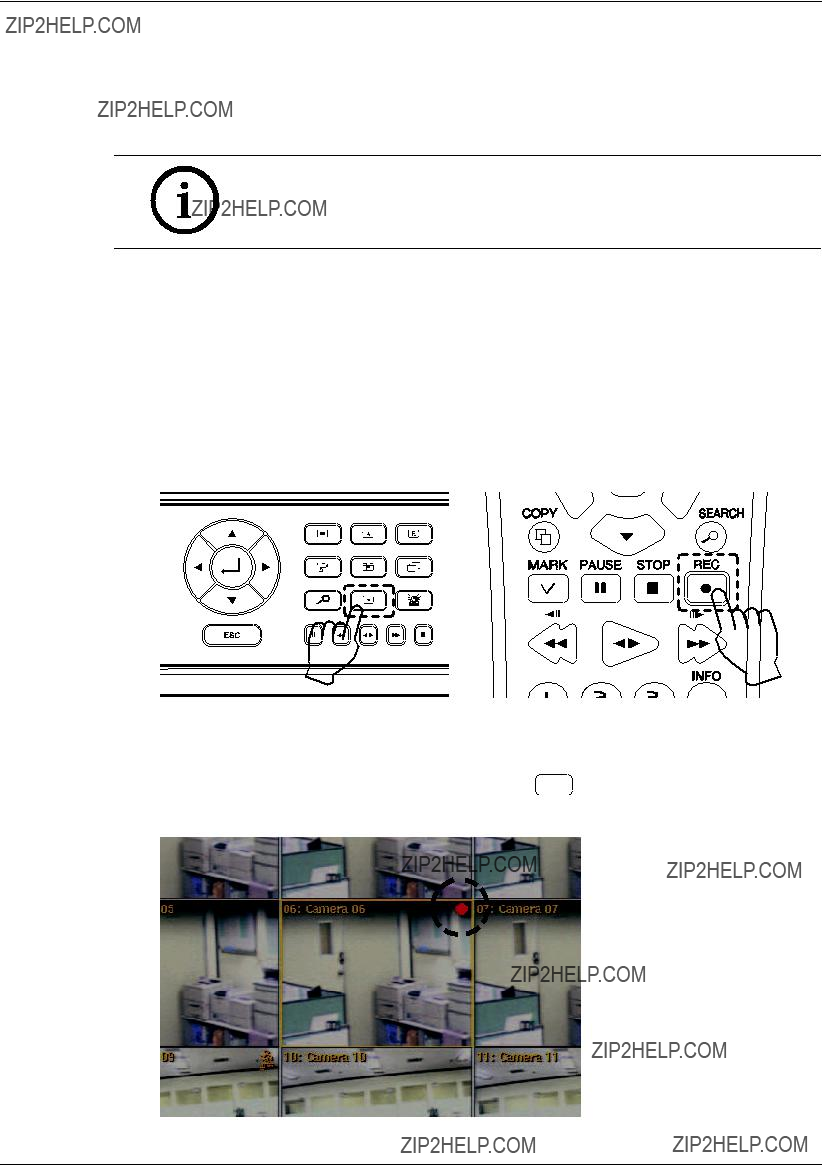
4.1Instant Recording
Ensure all the cameras are connected and that time and date have been set correctly.
Before you start recording, first SETUP the recording settings in the instant recording menu of the system setup.
1.Select the desired channel for instant recording.
2.Press the REC button on the remote control or press  button on the front panel to start record.
The red dot is blinking on the selected channel screen of the main monitor.
Figure 4.1 Rec buttons
3.Press the REC button on the remote control or press  button on the front panel to stop recording. If you stop instant recording, the recording mode will be changed into the scheduled recording mode and the red dot disappears.
Figure 4.2 Selected channel screen of the main monitor, showing the red dot.

Notes:
???You can not record the Instant and Continuous recording under the fol- lowing conditions.
-A HDD is not formatted.
-The channel has no video input for display.
-Overwrite is set to ???Off??? or ???Event Partition???, and normal partition is full.
-On the HDD setting, the event partition is set to 100%.
???You can not record the Input and Motion recording under the following conditions.
-A HDD is not formatted.
-The channel has no video input for display.
-Overwrite is set to ???Off??? or ???Normal Partition???, and event partition is full.
-On the HDD setting, the event partition is set to 0%.
-The schedule (Input/Motion) record is not set.
???HDD partition according to a recording type.
-Normal Partition: It is the space in the HDD that stores the continu- ous and instant recorded data. Once the normal partition is set to 0% (the event partition is 100%), you can not record the continuous or instant recordings.
-Event Partition: It is the space on the HDD that stores input and motion recorded data. Once the event partition is set to 0%, you can not record the alarm and motion recording.
???Priority of record.
Instant record > Input record > Motion record > Continuous record.

5 Search and playback
5.1Playback
It is possible to play a recorded image without stopping recording.
1.Select a channel you want to playback.
2.Press bB to play a recorded image of the previous 2 minutes of recording. The playback image will be displayed on the selected channel window.
Figure 5.1 Playback window
3.Press x (STOP) to stop the playback.
Note:
The playback window is ???xed and only in selected channel.
5.2Search
The various search functions of this unit can be used to go to the beginning of the desired picture. This unit is equipped with 4 search functions.
5.2.1Select source device
This item is used to set the playback or search device.
1.Press SEARCH button, the search menu is displayed.
2.Press ESC to move to the Title menu tab.
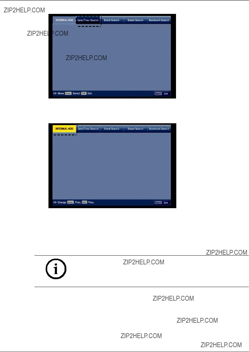
Figure 5.2 Search menu tab
3.Use b/B to select [INTERNAL HDD] then press ENTER.
Figure 5.3 Source device select menu
4.Use b/B to select the desired source device.
???INTERNAL HDD: Plays back or searches recorded contents of the internal HDD device.
???Source device: Plays back or searches backup contents of the source device.
5.Press ENTER to con???rm your selection.
Notes:
???While the backup is in progress, you can not search the data on the backup device.
???Do not remove the external USB device while the backup search is in progress from the USB device. It may cause a malfunction.
5.2.2Date/time search
Use to search recorded pictures by specifying date, hour and minute.

Figure 5.4 Date/time search menu
1.Select the [Date/time search] menu.
2.Use v/V/b/B to select the year, month, date, hour or minute column, then press ENTER.
3.Use b/B to input the date or time.
4.Press ENTER to con???rm it.
5.Select the [Update] icon then press ENTER.
The search result is displayed in the time table of the search menu.
6.Use the channel buttons on the front panel to select the channel(s) you want to play back.
7.Press bB or Click the [Play (B)] icon to start playback. The picture(s) is (are) displayed in the main monitor.
Figure 5.5 Playback showing system control bar
8.Press STOP (x) to stop playback and return to the search menu.
9.Press SEARCH or ESC to exit the menu.
Notes:
???Recorded data shown on the time graph will be displayed in different colors depending on the recording type.
-Blue: Continuous/Instant recording.
-Red: Input recording.
-Yellow:
-Gray: No recording.
???Use the ZOOM + button to view the detailed time by 6 hour intervals.
5.2.3Event Search
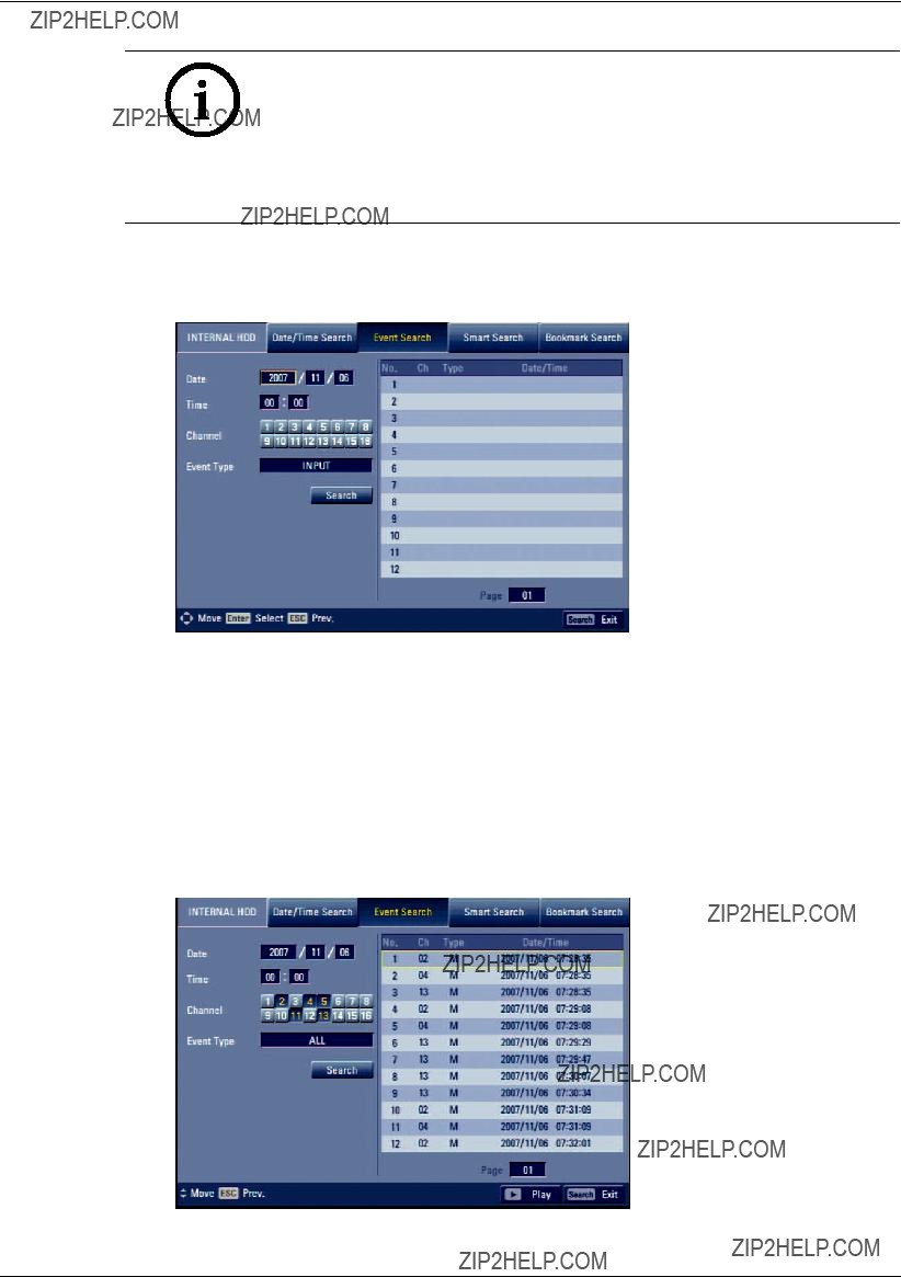
Search a recorded picture by date and type of event.
Figure 5.6 Event search menu
1.Select the [Event Search] menu.
2.Set the year, month, day and time.
-v/V/b/B: Moves to the previous or next column or changes the setting at the current position.
-ENTER: Selects the column or con???rms the setting.
3.Select the channel for event search using ENTER.
4.Use v/V/b/B to select the [Event type] then press ENTER.
5.Select the [Search] icon then press ENTER. The event list menu appears.
Figure 5.7 Event list
6.Select the recording data on the event list then press bB, click [Play (B)] or double click the selected data to start playback.
The picture is displayed on the monitor A.
7.Press STOP (x) to stop playback and return to the event list menu.
8.Press ESC repeatedly to exit the event search menu.
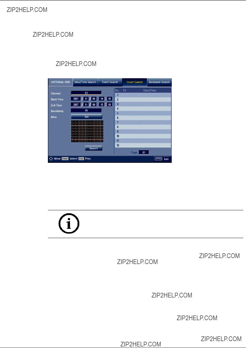
5.2.4Smart Search
Pictures recorded via motion detection can be searched by specifying the motion detection conditions.
Figure 5.8 Smart search menu
1.Select the [Smart search] menu.
2.Set the channel number, start time, end time and sensitivity options.
-b/B/v/V: Moves to the options or sets the selected option.
-ENTER: Selects option or con???rms the setting.
Note:
The time between the start time and the end time is automatically set at 1hour.
3.Select the [Set] in the [Area] option, then press ENTER. The picture from the selected camera is displayed.
4.Set the motion mask setting.
The area switches between active and inactive each time you press ENTER.
Click the one point and drag & drop the end point, to the right, to select the motion using the mouse. Click the one point and drag & drop the end point, to the left, to unselect the motion using the mouse.
The active areas are indicated in red.
5.Press ESC to exit the mask setting.
6.Select [Search] then press ENTER.
The motion detect list menu is displayed.
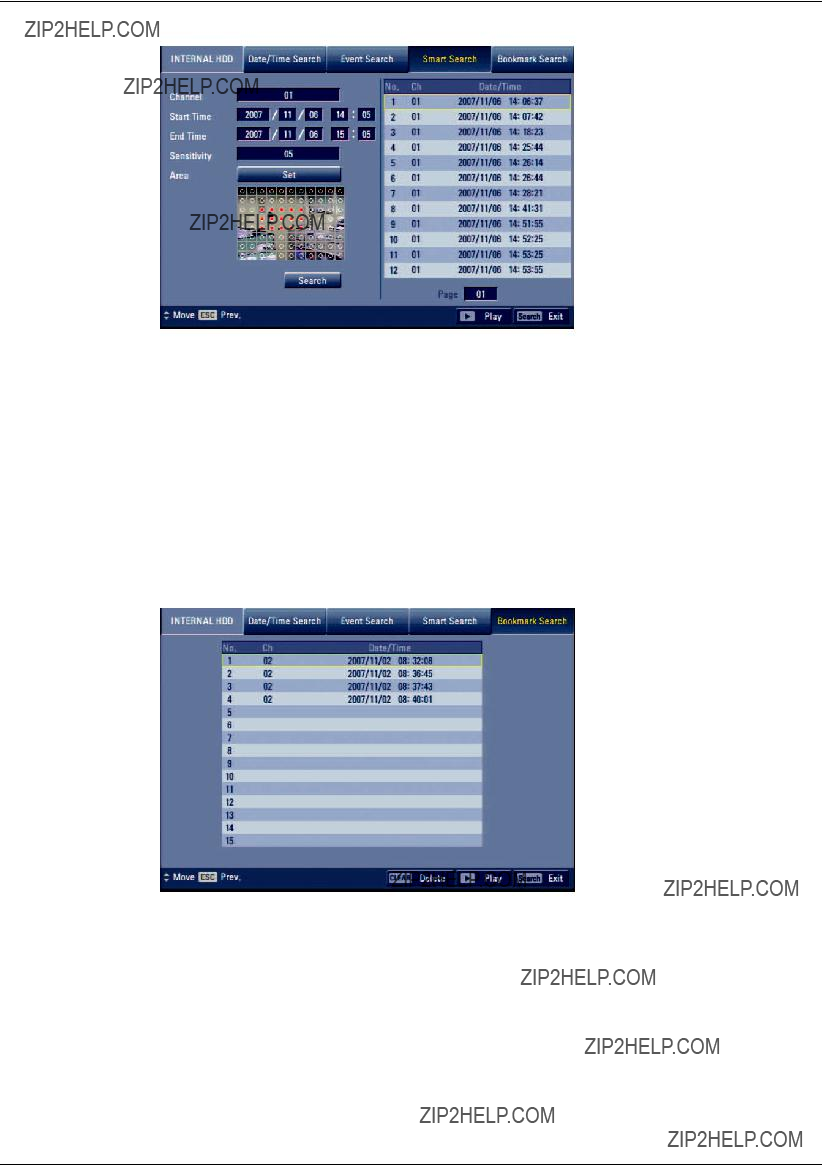
Figure 5.9 Motion detect list
7.Select the recording data on the motion detect list then press bB, click [Play (B)] or double click the selected data to start playback.
The picture is displayed in the main monitor.
8.Press STOP (x) to the stop playback and return to motion detect list menu.
9.Press ESC repeatedly to exit the smart search menu.
5.2.5Bookmark Search
Search the desired picture with a bookmark registered by the bookmark function.
1.Select [Bookmark Search] menu.
Figure 5.10 Bookmark search menu
2.Select the recording data on the list then press bB, click [Play (B)] or double click the selected data to start playback.
The picture is displayed in the main monitor.
3.Press STOP (x) to stop playback and return to the bookmark list menu.
4.Press ESC to exit the bookmark search menu.
Notes:
???If you want to delete the bookmark on the list, press the CLEAR button.
???Backup data can not be played back by a bookmark search.
???You can register a bookmark only in the single channel playback.
???You can not register a bookmark during instant playback
5.3Functions available during playback
Notes:
???You can play back the backup or export data in normal speed only.
???If you use the reverse frame skip function, a frame may be skipped.
???Multi channel play works only in the date/time search function.

5.4EXPORT
This unit can manually copy recorded images and audio from
1. Press COPY or click .
The export menu window appears.
Figure 5.11 Export menu window
2.Select a target device to export.
3.Select the channel number(s).
4.Set the start date/time and end date/time to copy.
5.Press COPY or Click  icon to start exporting.
The exported data will be authorized by the unit before saving and it can only be played back with the Archive player.
Notes:
???You can also use the COPY button on the front panel for export function.
-
-
???You can export the recorded data only in the live mode.
???If you use the external USB memory device, the external USB memory device has to be formatted on this unit. To format the USB memory device on the unit, refer to 3.24.8 Backup. In the backup menu you have to select device to be formatted and press ???Erase media???.
???Check the export device before you proceed.
???Export can not be executed while the backup is in progress.
???You can view the exported data with the supplied Archive player software.
???When you export the recorded data, the audio data will also be exported.
???When you export the recorded data the Archive player program will also be exported in the [ArchivePlayer] folder of the device. The exported data file name is made automatically as the [Channel name_export date_export time.exp] type.
???Do not remove the USB device while the export is in progress, it may cause a malfunction. If you reuse the removed device, you must format the media by using erase media options.
???The warning message appears for the conditions listed below.
-When the start date/time and end date/time are the same value.
-When the start date/time is later than the end date/time.
-The export media does not have enough space.
-When you set the time for data that does not exist.
???An external media has to be formatted on this unit to prevent a malfunc- tion.
???DVD+RW and
???You can format the external media with the backup tab in the setup menu.
???Export time is limited for 16 hours for 1 channel. For 2 channels is this 8 hours, 4 channels 4 hours and so on. If you want to archive 16 channels simultaneously you have a limit of 1 hour. When attempting more than 16 hours, the message ???Invalid export time range??? is displayed.
???You can export the customer log file to the USB device using the [File(Log)] button. The customer log file name is
The customer log file contains the following information.
-DVR information.
-Start date and time when the operator made the export.
-Start date and time of the export clip.
-End date and time of the export clip.
-Destination on which media the operator saved the export (USB or DVD/CD or IP [via network])
-Exported channel number(s)
-User ID that is logged on the system when an export was made.

6 Control Center
Control Center is the network program of the
The description pictures may differ from your OS (Operating System) type. The pictures used in this manual are based on Windows XP.
Note:
Do not use other applications with this Control Center program. This can cause memory shortage and Client program malfunction.
6.1PC minimum Requirements
x OS (Operating System): Windows 2000 or above, DirectX 8.1 or above.
x CPU: Intel Pentium III or above, AMD Athlon with 800 MHz or above.
x RAM: 512 MB or above.
x Graphics Card: AGP VGA with 64 MB Video RAM or above.
Recommended PC Requirements
???OS: Windows XP
???CPU: Intel Pentium IV
???RAM: 512 MB
???Graphics Card: AGP VGA with 128 MB Video RAM
6.2Control Center installation
1.Insert the Divar MR PC software CD which will be started automatically.
If the disc does not run automatically on your PC, open the Divar MR PC software CD and install the program manually.
2.Run the install ???le and install the programs to your computer following the InstallShield Wizard displayed.
3.After installation ???nishes you will ???nd the programs in the start menu of the computer.
Note:
The [Divar MR Alarm Noti???er] and [Divar MR Archive player] programs will be installed with the Control Center installation.
6.3Connecting to the DVR
6.3.1Register the Site Name
You should register a site name to control DVR by the Control Center.
1.
2.Select [Tools] > [Connection Information].

Figure 6.1 Connection list window
3.Select [Add] and the connection setup menu is displayed.
Figure 6.2 Connection setup window
4.Enter the site name, IP address and port.
-Site Name: Enter the description of the site.
-IP Address: Enter the IP Address or URL of the DVR.
-Port: Enter the Port number of the DVR. If it isn???t entered, the port number is set by default.
5.Select [OK].
Figure 6.3 Connection list window
6.Select [OK] to con???rm the settings. The registered site name is displayed.

Note:
In the case of entering the server name instead of the IP Address, set up the
DDNS con???guration properly in the server.
6.3.2User log on
1.Select the registered site name and right click the mouse.
2.Select [User Log on].
3.Enter the user ID and enter the password.
-ADMINISTRATOR: Operates the unit without limitations.
-Advanced User: Uses the live and search mode functions.
-Normal User: Shows the live image only.
Figure 6.4 Remote log on window
4.Select [OK] and the [Divar MR Control Center] main window is activated.
???If someone is logged on to the DVR using the Admin ID, you can not log on using the Admin ID.
???If you want to log off, right click the mouse on the site name and select [User log off].
???Up to 5 users can connect to the DVR system using the Control Center program as shown below.

6.4Main screen of DVR Control Center Program
Figure 6.5 Main screen of DVR Control Center Program
1.Program Menu
???File
-Exit: Exit the program.
???View
-OSD
>Channel Number: Displays or removes the channel number in the channel window.
>Site Name: Displays or removes the site name in the channel window.
>Camera Name: Displays or removes the camera name in the channel window.
>Playback Time: Displays or removes the date/time of playback data in the channel window.
>Select All: Displays all OSD options in the channel window.
-Sequence (Dwell Time): Select the sequence to 5 seconds, 10 seconds, 15 seconds or 20 seconds.
-Video Size: Select the video size from 100%, 150% or 200%.
-Language: Select the language for Control Center program.
???Tools
-Connection Infomation: To register a site name.
???Help
-Control Center Information: Displays Control Center Version Information.
2.Mode Selection Icons
???Live Mode
-Camera View: You can see the surveillance camera???s images in the window(s) and the camera information.
-Pan/Tilt/Zoom: You can control the PTZ cameras.
-Log View: Displays system log list.
???Search Mode
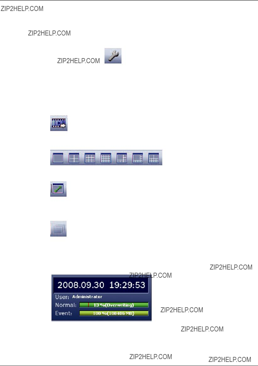
You can search the recorded data as shown below.
-Date/Time Search (See "6.6.1 Using the Date/Time Search function")
???Remote Setup Mode
You can set the con???guration of the unit.
- Camera / Display (See "6.7.1 Camera/Display setup")
-Schedule (See "6.7.2 Schedule setup")
- Event (See "6.7.3 Event setup")
-Network (See "6.7.4 Network setup")
-System (See "6.7.5 System setup")
3.Remote Export Icon
Click to display the Export
4.Screen Mode Selection Icons
When the icon is clicked, the screen will be changed to multiscreen view. If the icon is clicked again, the screen will be changed by sequence.
You can view the live window(s) in full screen view. To return to the normal screen, right click the mouse.
5.Sequence Icon
View all the channels in sequence. You cannot use sequence mode with the 16 multiscreen view.
6.Information Display Window
Displays current date and time, user information, and the remaining HDD status of the selected site name.
Figure 6.6 Information Display Window

6.5Live Mode
6.5.1Using the Camera View
1.Select the [Camera View] tab in the live mode.
2.Select the registered site name and double click the left mouse button or click the plus mark of the registered site name.
3.Select [Cameras] and double click the left mouse button or click the plus mark.
Figure 6.7 Divar MR Control Center Window
4.Select the channel number you want to view.
5.Click the channel number and drag and drop to live window position.
If you select [Cameras] and drag and drop to a live window then all channels are displayed.
6.Live image is displayed in the selected window.
Figure 6.8 Camera View window
7.Repeat steps
Notes:
???Configuration of camera view is set the first time only. This configura- tion setup is memorized for the next time and displayed as it is.
???No audio available in live mode only in playback.
6.5.2Using the live window
Playback of Recorded Data
A
B C
E

 D
D


Figure 6.9 Camera View window
1.Select the camera???s display window.
2.Select the date.
The day is displayed in a blue text when recorded data exists.
3.Select playback start time.
When using timeline to search a start time, use the zoom in/out icons for more detailed searches (4 step).
4.Select playback speed and mute speaker icon.
5.Start playback using these control buttons.
Notes:
???If you don???t want to play with sound click the speaker icon to mute.
???You can not use the playback function when you log in with the Normal User ID.
6.5.3Using the Pan/Tilt/Zoom function
You can control the PTZ cameras via the network.
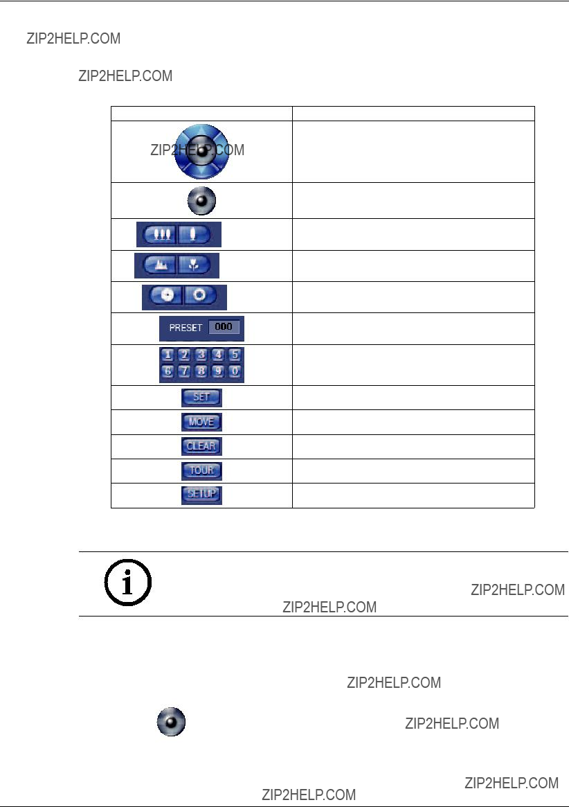
1.Select the PTZ camera channel window in the camera view mode.
2.Select Pan/Tilt/Zoom tab.
3.Use virtual remote control buttons to control the PTZ camera.
Use to Pan/Tilt the camera.
To confirm the preset position and set a menu option in the PTZ camera.
To adjust the camera zoom.
(ZOOM)
To manually adjust the focus of a camera.
(FOCUS)
To manually adjust the iris of a camera.
(IRIS)
Displays selected preset numbers
To input the preset number.
To register preset positions.
To move the camera to the preset position.
To delete a memorized preset position.
To start a preset tour.
To displays the setup menu of the PTZ camera.
Table 6.1 Virtual remote control button table
Notes:
???If someone is controlling a PTZ camera using the DVR, you cannot use the PTZ function and vice versa.
???You can not use the PTZ function when you log in with a normal user ID.
To Register preset positions
1.Move the camera to the point you wish by using the v/V/b/B.
2.Click the [SET] icon.
3.Select preset the number you wish to register.
4. Click the icon.
The position and its numbers are memorized.
5.Repeat steps
Note:
The preset range is available from 0 to 255 on this unit. However the actual preset range differs depending on the PTZ cameras.
Changing to a picture in a preset position
The following function is available only with cameras equipped with the preset function.
The preset function makes the PTZ camera move to the programmed preset position.
It is necessary to program preset positions for the PTZ camera beforehand.
1.Click the [MOVE] icon.
2.Use number icons to enter the memorized preset position???s index number, Click the icon.
The camera moves to the preset position and the picture from the camera in that position appears on the monitor.
To clear the preset position
You can delete a memorized preset position.
1.Click the [CLEAR] icon.
To tour the preset positions
You can tour all preset positions.
1.Click the [TOUR] icon.
All registered preset positions in the camera will be selected and the camera position image will be switched on to the active window.
2.You can stop the tour by clicking the [TOUR] icon.
Setup for PTZ camera
You can change the setting of PTZ camera using each item in the menu.
1.Click the [SETUP] icon.
SETUP MENU appears in the windows.
Note:
Refer to the manuals of the PTZ camera for more details.
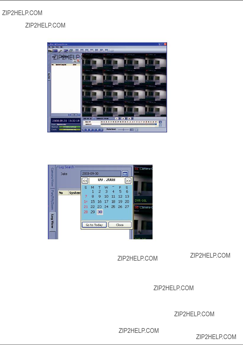
6.5.4Using the Log View function
You can see the system log list of selected site names in the remote setup tab via the network.
1.Select the log view tab. Log search menu appears.
Figure 6.11 The log search menu window
2.Click the date icon and select the day for the log search. (The selectable days are displayed in blue text color.)
Figure 6.12 The day select window
3.Click the search icon.
The system log is displayed in the list.
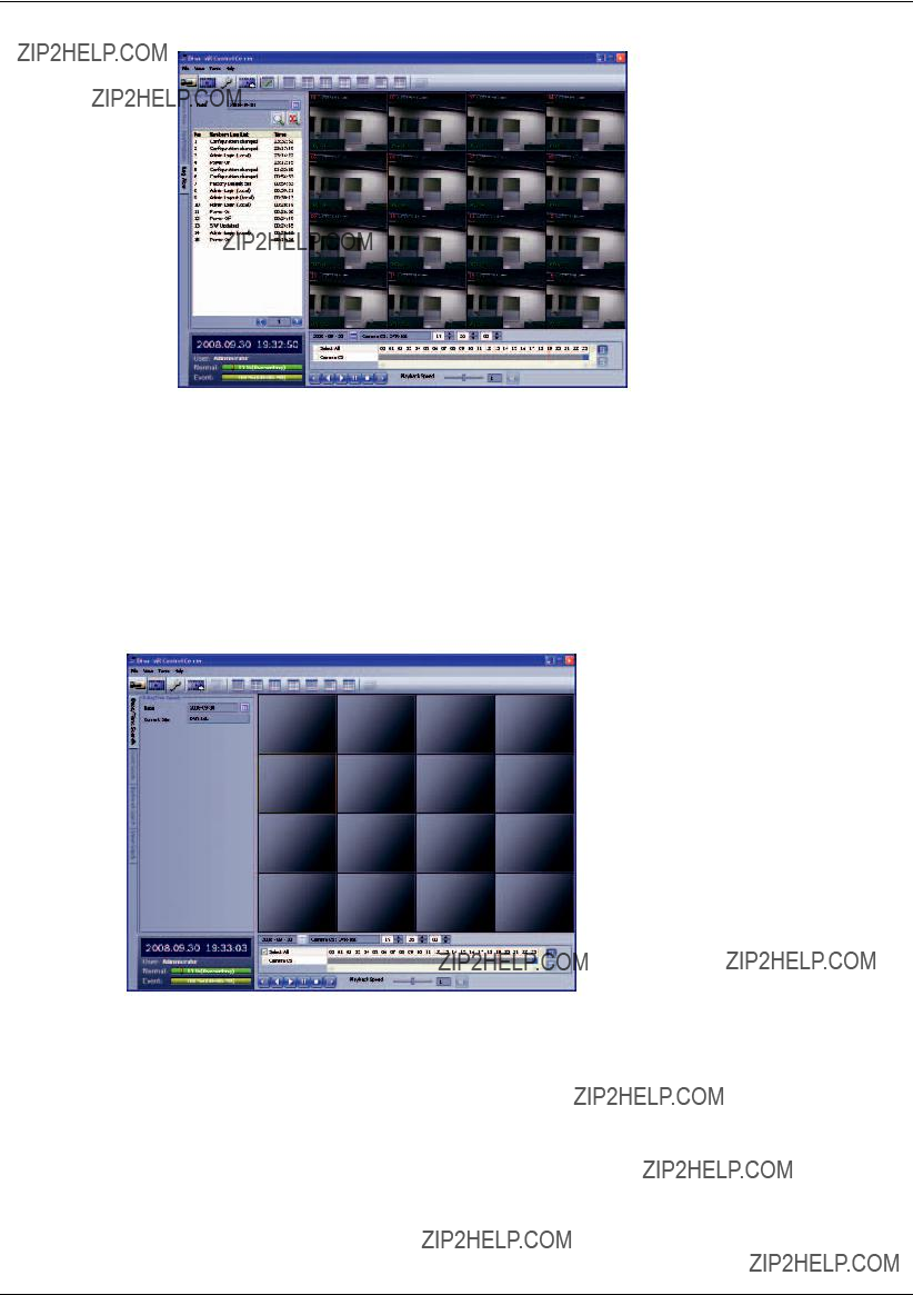
Figure 6.13 The system log list window
6.6Search mode
You can search the data of a selected site name in the remote setup tab via the network.
6.6.1Using the Date/Time Search function
Use to search a recorded picture by specifying date, hour and minute.
Figure 6.14 The Date/Time search window
1.Select the date/time search tab.
2.Click the date icon and select the day (the selectable days are displayed in blue color).
3.Select the channel window you want to view.

Check this box when you want to view from all camera channel windows.
Displays selected camera number.
Figure 6.15 Camera channel select window
4.Use the timeline and time input column to search recorded data.
Figure 6.16 Recorded data search window
5.Playback the searched data using the playback control buttons.
Figure 6.17 The playback control buttons
6.6.2Using the Event search function
Search a recorded picture by date and event type.
Figure 6.18 The Event search window
1.Select the event search tab.
2.Click the date icon and select the day.
(The selectable days are displayed in blue color.)
3.Select the camera channel for event search.
4.Select the event type.
5.Click the search icon.
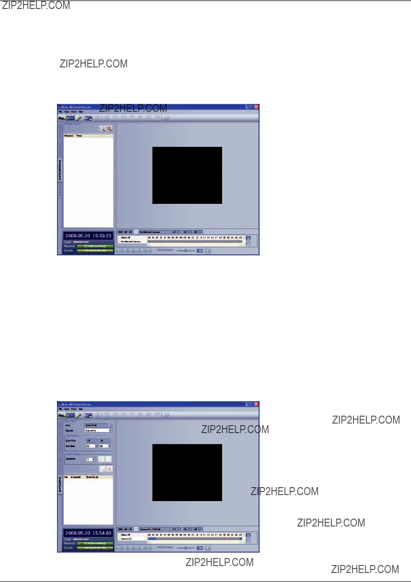
The event list is displayed.
6.Select the event from the event list.
7.You can play the searched data using the playback control buttons.
6.6.3Using the Bookmark search function
Search the desired picture with a registered bookmark using the bookmark function.
Figure 6.19 The Bookmark search window
1.Select the bookmark search tab.
2.Click the search icon.
All bookmark data is displayed in the list.
3.Select the data in the list.
4.Play the searched data using the playback control buttons.
6.6.4Using the Smart search function
Picture recorded via motion detection can be searched by specifying the motion detection conditions.
Figure 6.20 The Smart search window

1.Select the Smart Search tab.
2.Click the date icon and select the day.
(The selectable days are displayed in blue color.)
3.Select the camera channel.
4.Select the start time using the timeline.
Figure 6.21 Selected start time
5.Select the end time.
6.Select the motion sensitivity level and motion area on the display window using the mouse.
Cancel the selected area.
Select the all area.
Figure 6.22 The sensitivity level setting window
Selected area within red box.
Figure 6.23 Selected motion area
7.Click the search icon.
The smart search data is displayed.
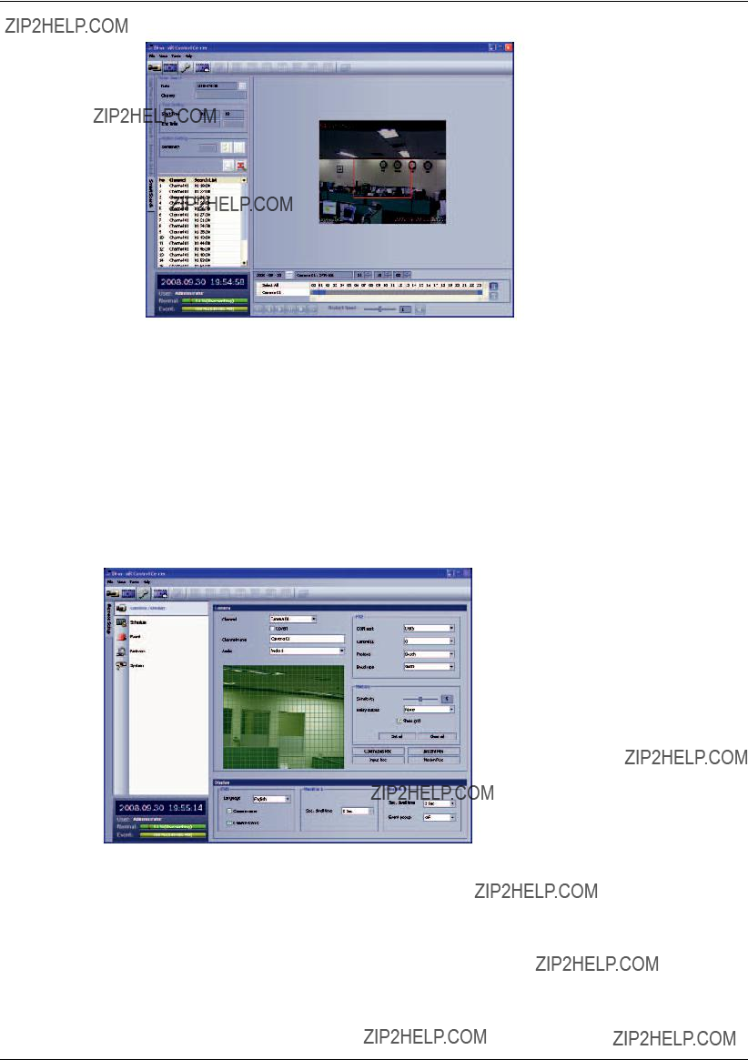
Figure 6.24 The searched data list
8.Select the channel from the list.
9.You can play the searched data using the playback control buttons.
6.7Remote Setup mode
You can set the DVR of a selected site name in the remote setup tab via the network.
6.7.1Camera / Display setup
Figure 6.25 The Camera/Display setup window
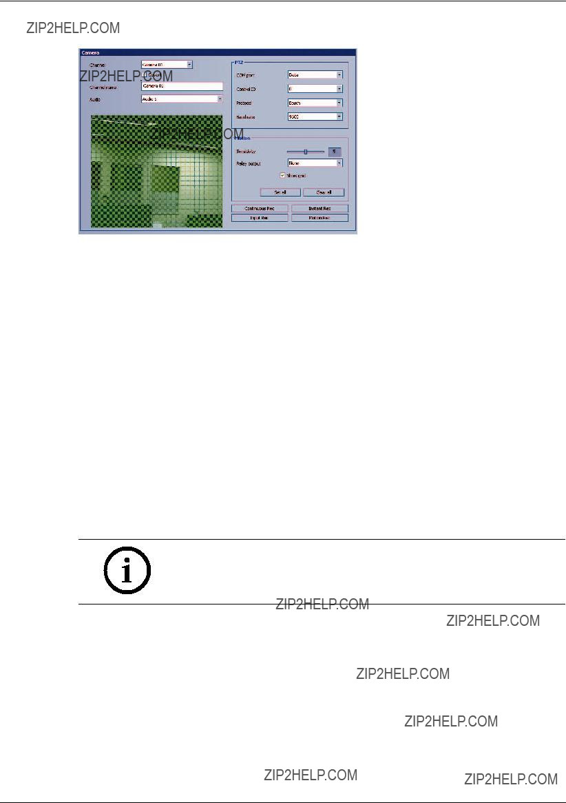
Camera Setting
Figure 6.26 The Camera setting window
1.Select a channel for settings.
If you want to block a channel from other users, mark up the convert option.
2.Enter the new channel name.
3.Select input audio channel.
4.Set the PTZ control options.
???COM port: Select the connected data port of the
???Control ID: Select the PTZ camera ID from 0 to 255. Make the same settings as the PTZ camera.
???Protocol: Select the protocol supported by PTZ camera.
???Baud rate: Select the communication speed (1200, 2400,4800,9600,19200 or 38400).
5.Set the motion options.
???Sensitivity: Set the sensitivity level for the created motion detection area. Sensitivity can be set from 0 to 10.
???Relay output: Select the number of the ALARM I/O port for the output alarm signal when motion is detected.
???Area: Select the desired motion detection area on the preview window screen using the mouse. Click the one point and drag & drop the end point to select the motion area.
Notes:
???If you want to display the grid, mark up the [Show grid] option.
???If you want to select the entire area, click the [Set all] button or click the [Clear all] button to cancel the selected area.
Continuous recording settings
1.Click the [Continuous Rec] button.
The continuous recording setting window appears.
Figure 6.27 The Continuous recording setting window
2.Set each option using the mouse (see "3.19.4 Continuous recording").
3.Click the [OK] button to con???rm the settings.
Instant recording settings
1.Click the [Instant Rec] button.
The instant recording setting window appears.
Figure 6.28 The Instant recording setting window
2.Set each option using the mouse (see "3.19.5 Instant recording").
3.Click the [OK] button to con???rm the settings.

Input recording settings
1.Click the [Input Rec] button.
The instant recording setting window appears.
Figure 6.29 The Input recording setting window
2.Set each option using the mouse (see "3.19.6 Input recording").
3.Click the [OK] button to con???rm the settings.
Motion recording settings
1.Click the [Motion Rec] button.
The instant recording setting window appears.
Figure 6.30 The Motion recording setting window
2.Set each option using the mouse (see "3.19.7 Motion recording").
3.Click the [OK] button to con???rm the settings.

Display settings
Figure 6.31 The Display setting window
1.Set the OSD options.
2.Set the monitor A option.
3.Set the monitor B options.
6.7.2Schedule setup
Figure 6.32 The Schedule setup window
1.Select a day of the week.
2.Mark up the desired recording option.
???Gray: No scheduled recording
???Blue (Continuous recording): Recording starts automatically from the preset time.
???Red (Input event recording): Recording starts automatically when the input is activated within a designated time.
???Yellow (Motion event recording): Recording starts automatically when motion is detected within a designated time.
-Green (Input+Motion recording): Recording starts automatically when the input is activated or motion has been detected.
???Blue+Red (Continuous+Input event recording): Recording starts automatically from the preset time. When the input is activated within a designated time, change the continuous recording mode to input event recording mode and recording starts automatically.
???Blue+Yellow (Continuous+Motion event recording): Recording starts automatically from the preset time. When the motion is detected within a designated time, change the continuous recording mode to motion event recording mode and recording starts automatically.
???Blue+Green (Continuous+Input+Motion event recording): Recording starts automatically from the preset time. When the input is activated or motion has been detected, change the continuous recording mode to motion event recording mode and recording starts automatically.
3.Select the channel to set the schedule.

4.Click the start time cell block and drag & drop to select a time period cell block.
or
Click the start time cell block of a channel and drag & drop across the channels to select the time period block for
The color of the cell blocks will change.
Schedule Copy settings
Figure 6.33 The Schedule copy setting window
1.Select the source day to copy.
2.Select the destination day from the day of the week, weekday or weekend options.
3.Click the copy button to copy the schedule data.
Exception day settings
Figure 6.34 The Exception day setting window
1.Mark up the exception day option.
2.Select the date to set the exception day schedule.
3.Mark up the desired recording option.
4.Select the channel to set the schedule.
5.Click the start time cell block and drag & drop to select a time period cell block. or
Click the start time cell block of a channel and drag & drop across the channels to select the time period block for multi channel setting at the same time.
The color of the cell block will change.

6.Enter the name of the exception day.
7.Click the add button to add the special day settings. The exception day is added to the list.
If you want to cancel the registered exception day, select the exception day in the list and click the delete button.
6.7.3Event setup
Figure 6.35 The Event setup window
1.Set the event options.
???Input: Displays the number of the ALARM I/O port.
???Input type: The alarm state can be set to either N.O. (Normally Open) or N.C. (Normally Closed).
???Linked camera: Select the connected camera channel with the ALARM I/O port.
???Relay out: Select the alarm output number of the
???Preset: Select the preset number. When the input is activated, the camera moves to the selected preset position and the picture of the camera in that position appears on the monitor.
2.Setting [Alarm ackn.] options.
???Alarm ackn.: Set the ???Manual??? or
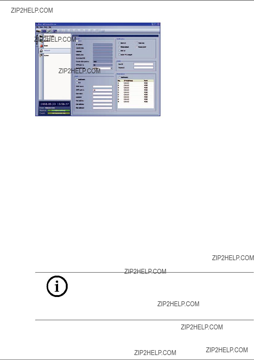
6.7.4Network setup
Figure 6.36 The Network setup window
TCP/IP settings
The [DHCP], [IP address], [Subnet mask], [Gateway], [Primary DNS], [Secondary DNS] and [Remote client port no.] option settings are not available in the client program. You can set these options in the system menu of the DVR.
???HTTP port no.: Enter the HTTP port number.
???Bandwidth limit: Enter the bandwidth to adjust the data traf???c.
Mail settings
Set the mail options.
???Noti???cation: When you mark up the noti???cation option, notify the user about unit operating information by
???TLS: Mark up when using the TLS (Transport Layer Security) function.
???SMTP server: Enter the SMTP server address.
???SMTP port no.: Enter the SMTP port number. Typically the TCP port used for SMTP is 25. However, in some cases it is better to change this port number for added ???exibility or security. If desired, change the port number (1 ~ 65535).
???User name: Enter the user name.
???Password: Enter the password.
???Mail address (1~3): Enter the mail address. You can input up to 3
Note:
The [SMTP server], [SMTP port no.], [User name] or [Password] settings are optional. The DVR can send
Notification
Set the noti???cation options.
???Alarm on: Sends an
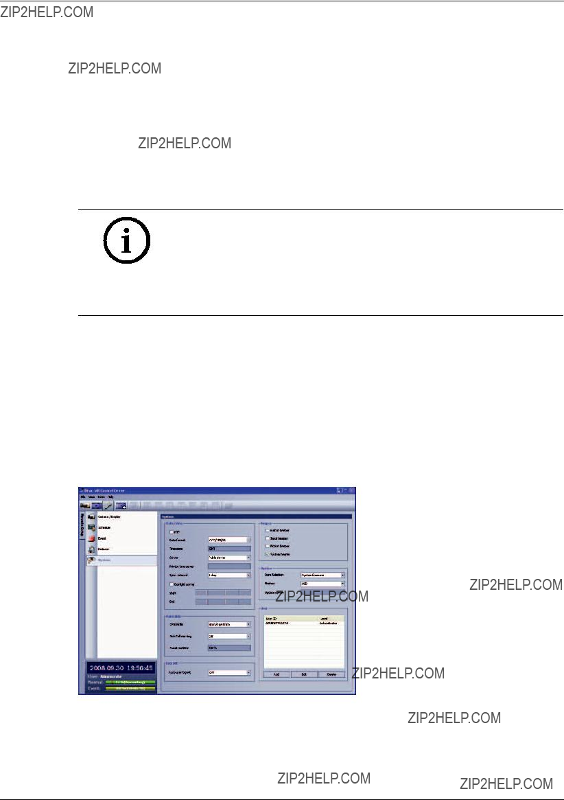
???Video loss: Sends an
???Motion detect: Sends an
???Power on/off: Sends an
???Disk full: Sends an
???Admin PW changed: Sends an
DDNS
???User ID: Enter the DDNS registered user name.
???Password: Enter the user password in [User ID].
Note:
The DDNS function is serviced using a TCP 8245 port by
In case the DVR is used in the network system with a firewall, open the TCP 8245 port so that DDNS data can get into firewall. For more detail on firewall setup, ask your network administrator and/or network service provider.
Emergency
???Noti???cation: Notify the Alarm Noti???er about unit operating information according to your noti???cation settings.
???IP Address, Port: Enter the IP Address and port number of the Alarm Noti???er program installed on the PC. The factory default port for this function is 9002. However, in some cases it is better to change this port number for added ???exibility or security. If desired, change the port number (1025 ~ 65535). You can set up to 9 IP address and port numbers.
6.7.5System setup
Figure 6.37 The System setup window
Date/Time settings
Set the date/time options.

???NTP: Mark up when using the NTP (Network Time Protocol) server for time adjustment.
???Date format: Select the date display format.
???Time zone: This option setting is not available in the Control Center program.
???Server: Select your time server.
The DVR will obtain the average time among 5 public servers (time.nist.gov,
???Private time server: Enter the private time server???s IP address or host name.
???Sync. interval: You can set synchronized interval with the NTP time server to 1 day, 1 hour, 1 week and 1 month.
???Daylight saving: Mark up when you use the daylight saving function.
-Start: Select the Daylight Saving start time.
-End: Select the Daylight Saving end time.
Hard Disk
???Overwrite: Select the overwrite recording type (Off, Normal partition, Event partition or All). This function is possible when the selected HDD type has fully recorded.
???Disk full warning: When the HDD has over???owed the warning message is displayed.
???Event partition: Sets the space of event partitions for event recording.
Log Out
???Auto user logout: Setting the logout time. You can set the auto logout time to 5 minutes, 10 minutes, 30 minutes or 60 minutes.
Sound settings
Select the beeper options.
???Button beeper: Makes a sound when using the buttons.
???Input beeper: Makes a sound when an input occurs.
???Motion beeper: Makes a sound when motion is detected.
???System beeper: Makes a sound when a cooling fan is not activated or the HDD has bad sector.
Update settings
Set the update options.
???Item Selection: Select the items for updating.
-PTZ Protocol: Set to PTZ Protocol update.
-System ???rmware: Set to System software update.
???Method: Select the update method.
-USB: Update from USB memory stick.
-Network: Update from the update server.
???Update server: Enter the IP address of the update server.
Note:
If you can not update from the update server, check the TCP/IP options and the IP address of the update server.
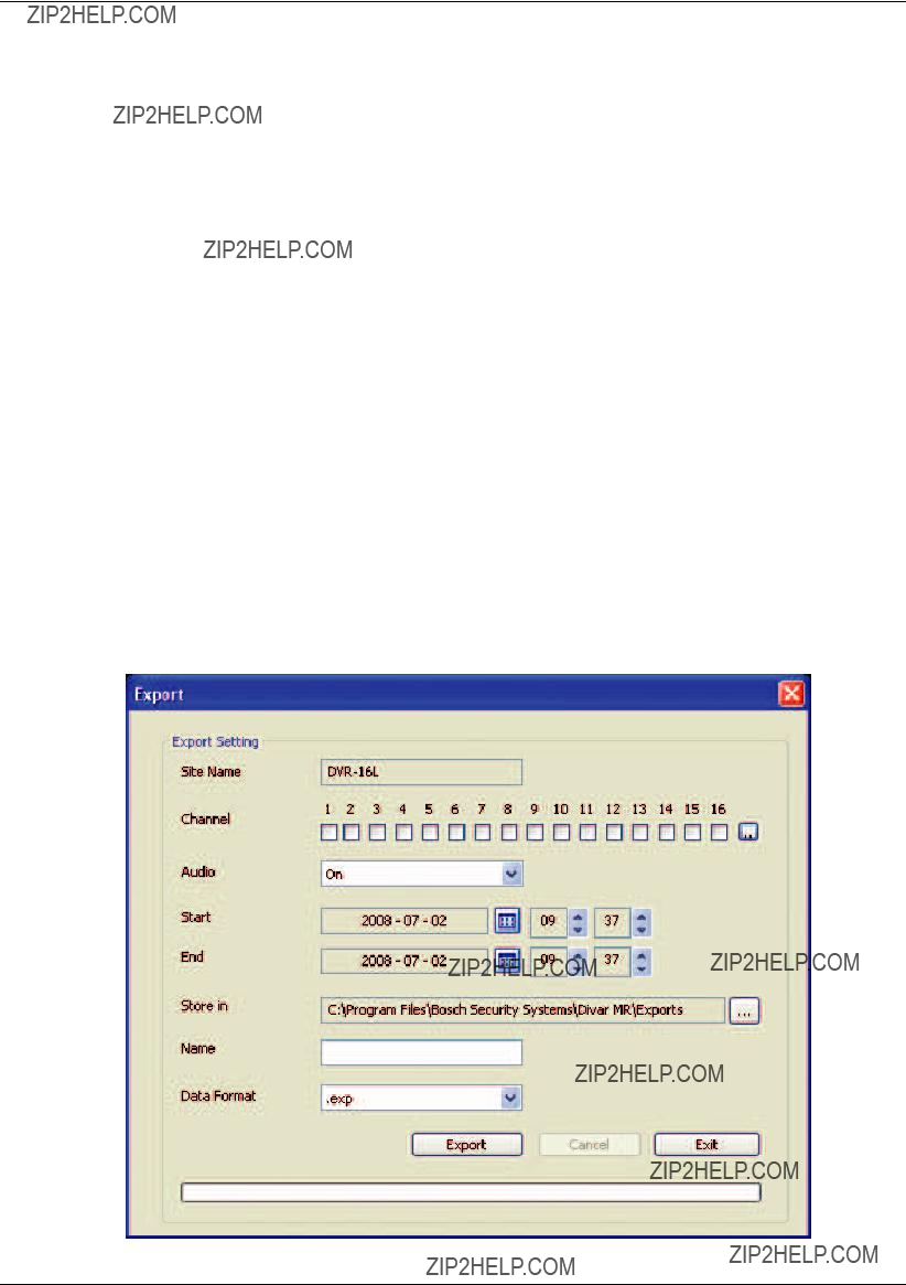
User settings
Add User
You can add user.
1.Click the ???Add??? button. User Setting window is displayed.
2.Enter the User ID and Password.
3.Enter the password again to verify.
4.Select the user level and then click ???OK??? to con???rm your selection.
Edit the registered User
You can change the User ID, password or user level.
1.Choose the user ID and then click the ???Edit??? button.
2.Change the ID, Password or User level, then click ???OK??? to con???rm your selection.
Delete registered User
1.Choose the user ID you want to delete
2.Click the ???Delete??? button.
6.8Remote Export Settings
You can copy the recorded images and audio data from the DVR unit to the PC. This function is permitted for Administrator and Advanced user.

???Site Name: Displays the selected site name.
???Channel: Select a channel(s) to export the data. You can select more than one channel. Click on the  icon to select or
???Audio: Set to On or Off to export the audio data.
???Start: Set the start date/time to copy.
???End: Set the end date/time to copy.
???Store in: Displays the current exported data save folder. You can select (or make) the folder on the computer to save the exported data. The initial save folder is "C:\Program Files\Bosch
Security Systems\Divar MR\Exports". If you want to change the exported data save folder, click the  icon and select the new folder.
???Name: Enter the ???le name of the export data. If you don't enter a ???le name, the default name CHx_start_time.exp is used.
???Data Type: You can select the saving ???le format between ???Native [*.exp]??? and ???AVI???. The Native ???le is saved with the extention of "*.exp" and the AVI ???le is saved with the extention of "*.avi". The saved "*.exp" ???le can playback using the Divar MR Archive Player program and "*.avi" ???le can playback using the Windows Media Player or the other ".avi" ???le player.
???Export: Click to start export the data of the selected export setting.
???Cancel: Click it to cancel data exporting.
???Exit: Click to exit the window.
How to export the data
1.Set the Channel options. You can select more than one channels.
2.Set the Start date/time options.
3.Set the End date/time options.
4.Select the folder on the computer to save the exported data.
5.Enter the export data name.
6.Select the data format.
7.Click the Export button to begin the export.
The export status will be displayed on the Status column.
8.Click the Exit button to exit the window.
Notes:
???The exported data file name is made as the [Channel number_Entered name.exp (or "avi")] type.
???If you do not assign the export directory, the export directory will be set to default directory and sub directory will be created with start date.
???If you
???If the export data size is larger than available size of the PC, the warrn- ing message will be displayed and you can not export the data.
???If you set the time for data that does not exist, the export function is not activated.
???The warning message appears for the conditions listed below.
-When the start date/time and end date/time are the same.
-When the start date/time is later than the end date/time.
???If you exit the export window during exporting, the export icon will be blinked until the export is finished and the Export completed window will be displayed.
7 Additional programs
7.1Alarm Notifier program
If you set the notification in the emergency option to On, the system sends a message according to the settings of the notification options in the setup menu. (See ???3.23.3 Notification???).
1.
Figure 7.1 The Alarm Notifier icon in the system tray
2.Whenever a noti???cation function occurs, a message box is displayed on the bottom right of the screen.
The message box is displayed for 5 seconds.
Figure 7.2 The message box window
3.Check the message.
4.Click the message box within 5 seconds to display the [Divar MR Alarm
or
Right click the mouse on the program icon in the system tray and select the [Check Message Box] option to display the [Divar MR Alarm
5.You can check all the subjects of received messages.
6.Click the  button to close the [Divar MR Alarm

7.2Main Screen of Alarm Notifier program
Figure 7.3 Main Screen of Emergency Agent
aDisplays message type.
bDisplays IP Address.
cDisplays received date and time.
dDisplays the port settings window.
eDisplays the search window.
fRefreshes the received message on the list.
gDetailed view of the received message.
hDeletes the selected message from the list.
iCloses the [Divar MR Alarm

7.2.1Port setting
Figure 7.4 Port setting window
1. Click the button.
The option window is displayed.
2.Enter the port number of the emergency agent listening port. The factory default port is 9002. However in some cases it is better to change this port number for added ???exibility or security. If desired change the port number (1025 ~ 65535).
3.Click the OK button to exit.
7.2.3Message search
Figure 7.5 Message search window
1. Click the button.
The message search window is displayed.
2.Select the search method.
???Event search: Search by selected type of event for the message.
???Date search: Search by selected date.
3.Click the Search button.
The search message is displayed on the [Divar MR Alarm

7.2.4Delete the message from the list
1. Select the message(s) you want to delete.
2. Click the button.
The con???rmation window is displayed.
Figure 7.6 The confirmation window
3. Click [Yes] to delete the message.
7.3Archive Player program
You can playback from the archived data on the PC using this program. The Archive Player program is saved automatically when you install the Control center program or archive the data.
7.3.1Main screen of Archive Player
Figure 7.7 The Archive Player window
???Program Menu.
-File(F)
>Open: Open the archived ???le.
>Print: Print image in window of Archive Player.
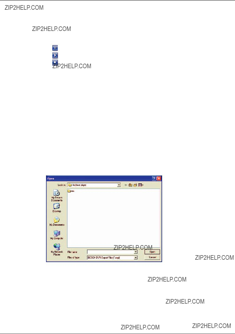
>Exit: Exit the program.
-Lang(L): Select the language for Archive Player program.
-Help(H)
>About Archive Player: Displays Archive Player information.
???Control Icons
-: Pauses playback.
-: Starts playback.
-: Stops playback.
???Watermark Setting
Check the option ???Check watermark???. If the file which is in playback differs from the file that is originally recorded, a warning window will appear.
???Video Information
-File Name: Displays the ???le name.
-Video Format: Displays the video type of the data.
-Time: Displays the recorded date and time of data.
-Recording Mode: Displays the save mode of the data. (continuous, motion or other).
-Camera Number: Displays the camera channel number of recorded data.
7.3.2Playing data
1.
The Archive Player window is displayed.
2.Select [File(F)] > [Open].
The open window is displayed.
Figure 7.8 The open window
3.Select the root directory of the USB device and select the desired ???le. An example of playable ???le format is ???Channel name_date_time.exp???.
4.Click the [Open] button.
The selected data is played back automatically.

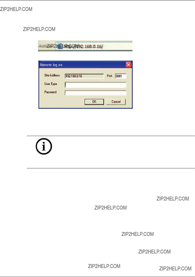
7.4Web Viewer program
7.4.1Logging into the Web Viewer
1.Start the web browser.
2.In the Address Box, enter ???HTTP://??? and the IP Address of the DVR.
3.Press ENTER, then the Web Viewer and the Remote log on menu will be displayed.
Figure 7.10 The Remote log on menu
4.Enter the User Type and Password.
5.Click [OK].
Notes:
???If the web viewer is not displayed, check the TCP/IP settings of the DVR.
???If you connect the DVR for the first time, the Security Warning window is displayed. You must click [Install] on the Security Warning window to install the program for using the Web Viewer. If you click [Don???t Install], the Web Viewer program is not available.

7.4.2Using the Web Viewer
You can control the live image using the Web Viewer.
Figure 7.11 The Web Viewer window
Mode select icon. Click to change the PTZ View mode or Live View mode.
Multiscreen selection icons.
Live screen display window.
7.4.3Live screen control
???Left mouse button: Select the channel. If you want to set to full screen, double click the selected channel. To return to the previous screen, double click again.
???Right mouse button: If you want to exit full screen mode, right click the mouse to return to the normal screen.
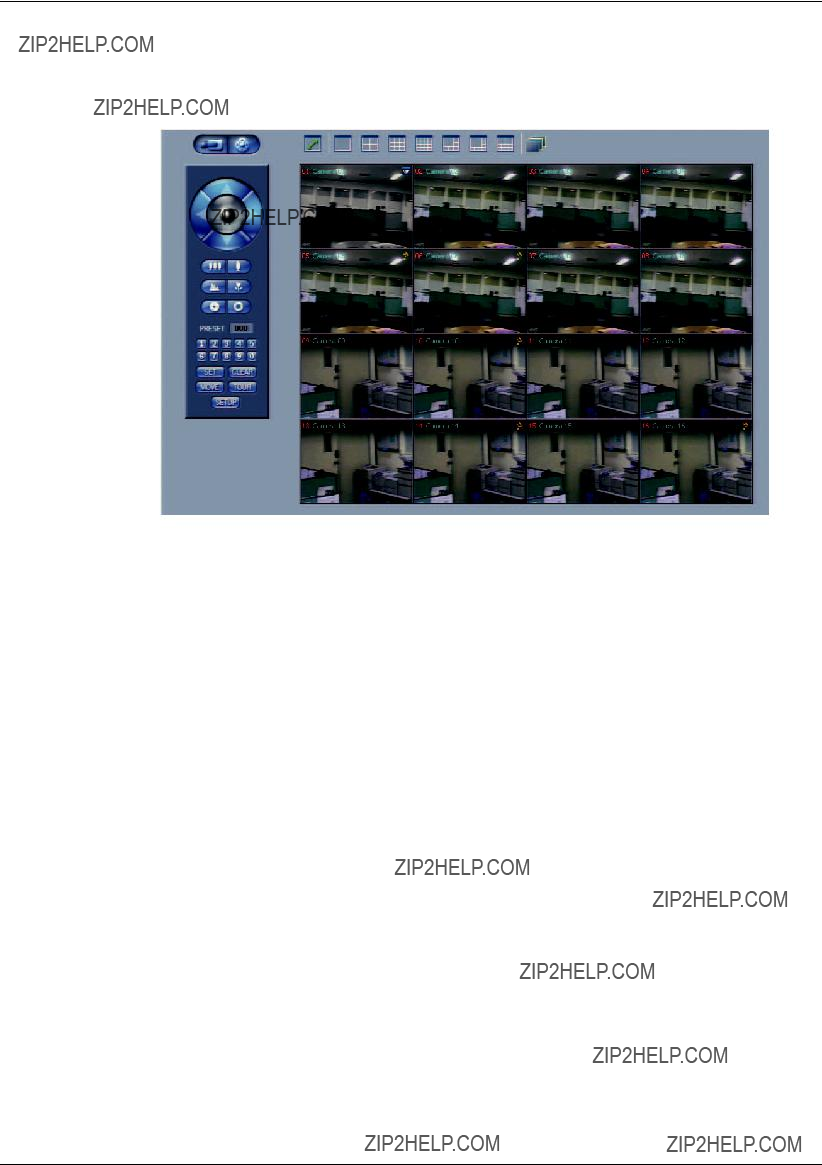
7.4.4PTZ View control
???Click the  icon to change the PTZ view mode. The PTZ virtual remote control is displayed.
Figure 7.12 The PTZ virtual remote control window
???Use virtual remote control buttons to control the PTZ camera.
For more details, refer to ???6.5.3 Using the Pan/Tilt/Zoom function???.

8 REFERENCE
8.1Troubleshooting
Check the following guide for the possible cause of a problem before contacting service.

Note:
If you observe any of the following symptoms:
???Some of the front panel LEDs do not light.
???The DVR does not operate normally.
You can reboot the DVR as follows:
???Turn off the DVR and turn it on again after a few seconds.
When the recorder does not work normally after rebooting, contact the service center.
8.2Recommended devices
8.2.1Supported USB Memory list
8.2.2Supported CD/DVD Media list
Note:
8cm 1.4G mini DVD is not supported.
8.2.3Supported function list for device
Note:
If you use a USB memory stick or USB HDD for configuration import/ export, you must disconnect the other external USB devices.

8.2.4Supported PTZ camera list


8.4Factory default configuration settings


8.5Recording Time Table (500GB HDD)

Note:
This recording time table is for reference only.
The recording time can be different depending on your surveillance environment.
8.6Recording Time Table (160GB HDD)


Note:
This recording time table is for reference only.
The recording time can be different depending on your surveillance environment.

8.7Specifications


Bosch Security Systems
www.boschsecurity.com
?? Bosch Security Systems, 2008