OmniView???
PRO2 Series KVM Switch
User Manual
F1DA104T
F1DA108T
F1DA116T
PRO2 Series
13
OmniView???
PRO2 Series KVM Switch
User Manual
F1DA104T
F1DA108T
F1DA116T
PRO2 Series
13

TABLE OF CONTENTS
Overview
Feature Overview . . . . . . . . . . . . . . . . . . . . . . . . . . . . . . . . . . . . . . . . .2
Equipment Requirements . . . . . . . . . . . . . . . . . . . . . . . . . . . . . . . . . . .3
Operating Systems . . . . . . . . . . . . . . . . . . . . . . . . . . . . . . . . . . . . . . . .4
Unit Display Diagrams . . . . . . . . . . . . . . . . . . . . . . . . . . . . . . . . . . . . .5
Specifications . . . . . . . . . . . . . . . . . . . . . . . . . . . . . . . . . . . . . . . . . . . .7
Installation
Using your PRO2
Selecting a Computer Using Keyboard Hot Key Commands . . . . . . . . .17 AutoScan Mode . . . . . . . . . . . . . . . . . . . . . . . . . . . . . . . . . . . . . . . . .18 Selecting a Computer Using
Belkin KVM Switches and Accessories
OmniView KVM Switches . . . . . . . . . . . . . . . . . . . . . . . . . . . . . . . . . .23
OmniView
OmniView Accessories and Adapters . . . . . . . . . . . . . . . . . . . . . . . . . .26
PRO2 Series FAQs . . . . . . . . . . . . . . . . . . . . . . . . . . . . . . . . . . . . . . . . . .27
Troubleshooting . . . . . . . . . . . . . . . . . . . . . . . . . . . . . . . . . . . . . . . . . . . .30
Information . . . . . . . . . . . . . . . . . . . . . . . . . . . . . . . . . . . . . . . . . . . . . . .34
OmniView???
PRO2 Series KVM Switch
Congratulations on your
purchase of this Belkin OmniView PRO2 Series KVM
Switch (the PRO2). Our diverse
line of KVM solutions exemplifies the Belkin commitment to
delivering
Belkin has designed and developed this PRO2 with the server administrator in mind. The result is a KVM Switch that surpasses any other switch on the market. The PRO2 is engineered to work with the most advanced server room and laboratory environments, offering intuitive port indicators,
This manual will provide details about your new PRO2, from installation and operation to
For quick and easy installation, please refer to the Quick Installation Guide included in your PRO2 packaging.
Thank you for purchasing the PRO2. We appreciate your business and have confidence that you will soon see for yourself why over 1 million Belkin OmniView products are being used worldwide.
Package Contents
???OmniView PRO2 Series KVM Switch
???Adjustable
???
???User Manual
???Quick Installation Guide
???
???Registration Card
1

OVERVIEW
The PRO2s allow you to control up to a maximum of 256 computers with one keyboard, monitor, and mouse. They support PS/2 input devices (keyboard and mouse) as well as VGA, SVGA, XGA, and
They support both PS/2 and USB output. This enables
Feature Overview
Hot Keys:
Hot key functionality allows you to select a desired port using designated key commands. By using a simple hot key sequence on your keyboard, selecting one computer from as many as 256 computers is instantaneous. For a listing of complete hot key instructions and commands, see pages
AutoScan:
The AutoScan feature allows you to set your PRO2 to scan and monitor the activities of all operating computers connected to the
Video Resolution:
Through a 400MHz bandwidth, the PRO2s support video resolutions of up to 2048x1536@85Hz. To preserve signal integrity at these higher resolutions, your PRO2 requires
Flash Upgrade:
Flash upgradeable firmware allows you to install the latest firmware for your PRO2. This enables your PRO2 to maintain consistent compatibility with the latest devices and computers. Firmware upgrades are free for the life of your PRO2. Refer to the enclosed flash upgrade instruction document or visit us at belkin.com for complete upgrade information and support.
The OSD feature simplifies server management by allowing you to assign individual names to each connected server throughout the system. It provides a visual means of switching between computers and setting the time interval for the AutoScan function.
2

OVERVIEW
LED Display:
An LED display on the face of the PRO2 serves as a status monitor. An LED next to each
When
Equipment Requirements
Cables:
To connect to the PRO2, each PS/2 computer requires one VGA cable, one PS/2 keyboard cable, and one PS/2 mouse cable. Keyboard and mouse cables must have PS/2
Video resolution support of up to 2048x1536@85Hz requires use of a
Belkin highly recommends that you use OmniView
3

OVERVIEW
available in both USB and PS/2 connector types. The following cables are recommended for your PRO2:
OmniView
OmniView
USB Style
Operating Systems
OmniView PRO2 Series KVM Switches are for use on CPUs using:
Platforms:
???Windows?? 95/98/2000/Me/NT??/XP
???DOS
???Turbolinux?? and all Linux?? distributions
???Novell?? NetWare?? 4.x/5.x
???Mac (with USB support)
???Sun (with USB support)
Keyboards:
??? Supports
Mice:
???Microsoft??
???Microsoft
Monitor:
???VGA
???SVGA
???MultiSync??
4

OVERVIEW
Side View of the PRO2:
F1DA108T
5

OVERVIEW
Front View of the PRO2:
F1DA108T
Back View of the PRO2:
F1DA108T
USB 04
USB 03
6

OVERVIEW
Specifications
Part No.: F1DA104T, F1DA108T & F1DA116T
Power:
Computer Connections Supported:
4 (F1DA104T)
8 (F1DA108T)
16 (F1DA116T)
Keyboard Emulation: PS/2
Mouse Emulation: PS/2
Monitors Supported: VGA, SVGA, MultiSync, and LCD (optional adapter may be required)
Max. Resolution: 2048x1536@85Hz
Bandwidth: 400MHz
Keyboard Input:
Mouse Input:
VGA Port:
Port LED Indicators: 4 (F1DA104T) 8 (F1DA108T) 16 (F1DA116T)
Enclosure: Metal enclosure with
Dimensions:
(F1DA104T) 11 x 1.75 x 6 inch (279mm x 44.5mm x 150mm) (F1DA108T)17.25 x 1.75 x 7.5 inch (438mm x 44.5mm x 190mm) (F1DA116T) 17.25 x 3.5 x 7.5 inch (438mm x 89mm x 190mm)
Weight:
(F1DA104T) 5.3 lbs. (2414.5 grams) (F1DA108T) 9.2 lbs. (4181.5 grams) (F1DA116T) 12 lbs. (5472.5 grams)
Operating Temp.: 32?? to 104?? F (0~40?? C)
Storage Temp.:
Humidity:
Warranty: 5 years
Note: Specifications are subject to change without notice.
7

INSTALLATION
Where to Place the PRO2:
The enclosure of the PRO2 is designed for standalone or
Consider the following when deciding where to place the PRO2:
???whether or not you intend to use the
???the lengths of the cables attached to your keyboard, monitor, and mouse;
???the location of your CPUs in relation to your console;
???and the lengths of the cables you use to connect your computers to the PRO2.
Cable Distance Requirements:
For PS/2 computers:
VGA signals transmit best up to 25 feet. Beyond that length, the probability of video degradation increases. For this reason, we recommend
that the length of the cables between the PRO2 and the connected computers does not exceed 25 feet.
Note:
If you need your console to reside further than 25 feet from the PRO2, we recommend using the Belkin CAT5 Extender (F1D084) with a standard CAT5 UPT cable. By using this device, you may increase the distance between your PRO2 and your keyboard, mouse, and monitor by as much as 500 feet without risking signal degradation.
For USB computers:
USB signals can be transmitted up to 15 feet between the PRO2 and the CPU. Beyond 15 feet, the probability of signal failure is likely, and this may cause the device to fail.
Cautions and Warnings:
Avoid placing cables near fluorescent lights, air conditioning equipment, or machines that create electrical noise (e.g., vacuum cleaners).
8
INSTALLATION
Cautions and Warnings:
Before attempting to connect anything to the PRO2 or your computer(s), please ensure that everything is powered off. Plugging and unplugging cables while computer(s) are powered on may cause irreversible damage to the computer(s) and/or the PRO2(s). Belkin Components is not responsible for damage caused in this way.
Installing the PRO2 into a Server Rack:
Bracket Installation (F1DA108T and F1DA116T only)
Eight- or
1.Remove the adjustable brackets from the box. (The adjustable brackets allow you to set the PRO2???s face flush with the ends of the rails or to extend the PRO2 past the front of the rails).
2.Determine how far you would like the PRO2 to protrude from the rack. Select a
3.Attach the bracket to the side of your PRO2 using the Phillips screws provided. (Refer to diagram above).
4.Mount the PRO2 to the rack rail assembly.
Note: If this PRO2 will be
9
INSTALLATION
Your PRO2 is now mounted securely into the bracket and you are ready to connect cables to the back of the unit.
Note for Belkin PRO Series owners
Single PRO2 Installation
This section provides complete instructions for the hardware setup of a single PRO2. (F1DA104T, F1DA108T, and F1DA116T)
PS/2 Installation:
Keyboard, Video, and Mouse Connections
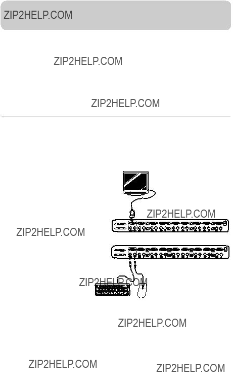
Connect the Console:
1.Connect the monitor to the PRO2. Attach your monitor cable to the HDDB15 female port on the back of the PRO2 labeled "Console VGA".
2. Connect the PS/2 keyboard cable to the keyboard port on the back of the PRO2 in the "Console" section.
3. Connect the PS/2 mouse cable to the mouse port on the back of the PRO2 in the "Console" section.
Attach the power supply to the DC power jack labeled "DC 12V, 1A" located on the rear of the PRO2. Once the power is connected to a power source, the LED for port 01 will begin flashing. Sequentially push the
10
INSTALLATION
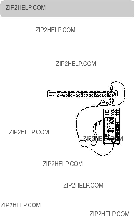
Connect the Computer:
PS/2 Installation
1.Using an OmniView KVM Cable (Belkin part#
2.Connect the PS/2 keyboard and PS/2 mouse connectors of the cable to the keyboard and mouse ports on the computer. Connect the other ends of the cables to the keyboard and mouse ports located directly underneath VGA 01 on the PRO2 (Belkin part #
3.Repeat steps 1 and 2 for each additional PS/2 computer you wish to connect.
USB Installation:
Boot the computer you wish to connect via USB as you would normally with the keyboard, monitor, and mouse connected directly to the computer. After the operating system finishes loading, connect the PRO2 to the USB computer using the USB
11

INSTALLATION
1. Using a USB KVM Cable (Belkin part#
the back of the PRO2 for the appropriate port you wish to connect to (for example, "VGA 02").
2. Connect the

 connector to an available USB port on your USB computer. Connect the other end of the USB cable (with the
NOTE: We recommend you attach the KVM cable directly to a free USB port on your computer.
Repeat steps 1 and 2 above for each additional USB computer you wish to connect.
Connecting Multiple PRO2s
You can
Note: A
PRO2 and is available through your Belkin reseller or online at belkin.com.
All PRO2s feature a ???BANK DIP??? switch. The BANK DIP switch is used for proper identification and use of PRO2s in a
???For a
???For
12

INSTALLATION
BANK DIP Switch Configuration Chart
Note: ???On??? is the down position.
Example:
Four
13

INSTALLATION
Installation
Before You Begin:
1.Make sure that all computers are powered off and that each PRO2 has been assigned a unique BANK address.
2.Place Master and Slave switches in the desired location. Make sure all are turned off and unplugged from the power source.
3.Connect the Console monitor, keyboard, and mouse to the Console ports of the Master switch or Bank 00, as described previously in this installation guide.
Connecting the Master Switch to the First Slave Switch:
4.Using the
5.Connect the other end of the
Adding Additional Slave Units:
6.Using the
7.Connect the other end of the
(for example, BANK 02).
8.Repeat steps 6 and 7 for additional PRO2s you wish to
14

INSTALLATION
Example of
Slave Input
Connecting the Computers:
9.Connect all computers to the Master and Slave switches. Refer to ???Single PRO2 Installation??? on page 10 for instruction on how to connect the Console and the computers to the PRO2.
10.Connect the power supply to the Master switch. Power up the Master switch. You should see the Master switch light up and display the digits ???00???, indicating its BANK address.
11.Power up the Slave switches sequentially, beginning with Bank 01, by connecting each unit???s power supply. Each switch should display its corresponding BANK address number as it is powered up.
Note: If the PRO2s do not enumerate correctly, reset the Master switch (BANK 00) by simultaneously pressing the "BANK +" and "BANK
If the switches still do not enumerate correctly, check that all switches have the correct BANK address assigned to them and that all
12.Verify that the Master unit has detected all Slave switches by scrolling through the BANKS using the BANK up and BANK down buttons.
If all Slave switches are detected properly, the LED display on the Master switch will register and display the attached Slave switch???s BANK address.
15

USING YOUR PRO2
Powering up the Systems
Once all cables have been connected, power up the computers that are attached to the PRO2. All computers can be powered on simultaneously. The PRO2 emulates both a mouse and keyboard on each port and allows your computer to boot normally.
The computer connected to port ???1??? will be displayed on the monitor. Check to see that the keyboard, monitor, and mouse are working normally. Proceed to do this with all occupied ports to verify that all computers are connected and responding correctly. If you encounter an error, check your cable connections for that computer and reboot. If the problem persists, please refer to the Troubleshooting section in this manual.
Using Your PRO2:
Now that you have connected your Console and computers to your PRO2, it is ready for use.
Select connected computers by either the
16

USING YOUR PRO2
Selecting a Computer Using Keyboard Hot Key Commands:
Switch to the next or previous port with simple keyboard key sequences using the ???Scroll Lock??? key and either the up or down arrow keys. To send commands to the PRO2, the ???Scroll Lock??? key must be pressed twice within two seconds. The PRO2 will beep, confirming that it is in hot key mode. Next, press the up or down arrow keys, and the PRO2 will switch to either the prior port or the next port.
With a
 +
+  +
+ 


Switch to BANK 00, Port
Note: You will have approximately five seconds to complete each hot key sequence.
With


 +
+

 +
+
Page
Up


 +
+

 +
+
Page
Down
17

USING YOUR KVM SWITCH
With a
AutoScan Mode:
+


 5
5
Pressing the AutoScan button on the PRO2 will activate the AutoScan function. In AutoScan mode, the PRO2 remains on one port for a
Note: There is no mouse or keyboard control in AutoScan mode. This is necessary to prevent data and synchronization errors. If the user is using the mouse or keyboard when the PRO2 is switching between ports, data flow may become interrupted and could result in erratic mouse movement and/or
Press any button on the front panel or any key on the keyboard to disable AutoScan.
Selecting a Computer Using
You can directly select which computer you wish to control by pressing the
BANK Up and BANK Down Scroll Buttons:
Pressing the BANK + and BANK ??? scroll buttons on the Master switch will allow you to switch between the
The BANK + button will take you to the next BANK. For example, when you are at the Master switch (BANK 00) and want to check computers on BANK 02, pressing the BANK + button will take you to BANK 02. As a default, the
18
USING YOUR PRO2
first active computer will be displayed on the Console monitor. Use the
The ???BANK ??? ??? button will take you to the previous BANK. For example, when you are at BANK 02 and want to check computers in BANK 01. Pressing the ???BANK ??? ??? button will take you to BANK 01. As default, the first active computer will be displayed on the Console monitor. Use the
Keyboard Hot Key Commands:
Conveniently command the PRO2 to switch ports through simple keyboard key sequences. To send commands to the PRO2, the ???Scroll Lock??? key must be pressed twice within two seconds. You will hear a beep for confirmation. Below is a complete list of hot key commands:
Note: you will have approximately five seconds to complete each hot key sequence.
19

USING YOUR PRO2
To access the
The main OSD menu is shown below. It displays the current selected BANK. If you have only one PRO2, it will display ???BANK 00???.
Setup Menu
Main Menu
A ??? ?????? symbol indicates that the computer is powered.
If a computer is connected and is powered up, but the OSD menu does not display a ??? symbol, you will have to reset the PRO2 to
(PGUP/DN): BANK: Select previous BANK by pressing the ???Page Up??? key and next BANK by pressing the ???Page Down??? key.
(Insert): RENAME: Name each computer (up to 15 characters).
(ENTER): SAVE: Save the content input.
(TAB): SETUP: Open ???Setup??? menu.
(ESC): EXIT: Exit the
20

USING YOUR PRO2
AutoScan Time:
Specifies the amount of time the PRO2 remains on a port before switching to the next port while in AutoScan mode. You may select different time
OSD Display Time:
Specifies the amount of time the OSD menu is displayed. Also specifies the amount of time the ???Port Identification??? tag displays
For both settings, you may use the arrow keys to navigate. After you have selected the desired time intervals, push ???Enter??? key to save the entry. Press the ???ESC??? key to go back to the original OSD menu screen.
Press the ???ESC??? key again to exit the
Note: If there are Slave units connected, and the AutoScan time and OSD display time settings are set on the Master unit, the settings will also apply to all slave units.
Updating Firmware:
To update your firmware, download the appropriate firmware file and utility from belkin.com. The utility automatically guides you through the process of updating the firmware on your PRO2.
Cautions and Warnings:
We strongly recommend that you update your firmware only if you are currently experiencing mouse and keyboard problems with your PRO2, as reconfiguring software may lead to unexpected operational problems. Please contact Belkin Tech Support if you need assistance.
To update the firmware, you will need the following items:
1.A separate computer running Windows 95, 98, or Me. This computer must not be connected to the CPU ports on the PRO2.
2.An available parallel port on the computer.
3.A custom flash cable (DB25
4.Firmware update files available at belkin.com.
21

USING YOUR PRO2
Connecting Computers:
1.Connect a keyboard, monitor, and mouse to the computer you prepared for firmware update. It must run Windows 95, 98, or Me.
2.Connect the power adapter to the PRO2. Be sure that all connected com- puters are powered off at this moment.
3.Connect the custom flash cable (DB25
Setting the PRO2 into Flash Mode:
The DIP switch should be set to the specified settings when you are attempting to update a particular firmware. For example, set DIP switch 1 to ???ON??? to flash update the main firmware of the switch.
Note: F1DA116T requires that you flash update two firmwares for the mouse and keyboard, separately.
1.Once the above steps have been completed, run the Flash software exe- cutable. Make sure that the appropriate Flash DIP switch is set to the ???on??? position. Only one firmware can be flashed at one time.
2.After the Flash update has been completed unplug the power supply from the PRO2.
3.Set all DIP switches to the Off position.
4.You are now ready to use your PRO2 or continue flashing a different component if necessary.
22

BELKIN KVM SWITCHES AND ACCESSORIES
OmniView KVM Switches
OmniView E Series. This series of desktop OmniView KVM Switches allows you to control two or four PS/2 computers from one Console and makes switching between computers more convenient. Designed for compatibility with your PS/2 platform, it reduces desktop clutter and provides a simple, reli- able solution at a lower price point.
The E Series KVM Switch supports
F1DB102P E Series
F1DB104P E Series
OmniView SOHO Series with Audio. This innovative design provides
to unplug and
23

BELKIN KVM SWITCHES AND ACCESSORIES
F1DS102P SOHO Series
OmniView PRO2 Series. The OmniView PRO2 Series KVM Switches deliver reliability, performance, and centralized control necessary for today???s enterprise environment. This series of KVM Switches enables you to control multiple platform servers from a single Console. Available in the
F1DA104T PRO2 Series
F1DA108T PRO2 Series
F1DA116T PRO2 Series
OmniView MATRIX2 Series. The OmniView MATRIX2 Series 2x8- and
24

BELKIN KVM SWITCHES AND ACCESSORIES
OmniView
OmniView
OmniView
of
Gold Series. These cables are known for their 24k
PRO Series Plus. The PRO Series Plus Cables are
25

BELKIN KVM SWITCHES AND ACCESSORIES
OmniView Accessories and Adapters
Belkin KVM technology includes various accessories and adapters to complete your KVM solution. The Adapter Series converts Mac, Sun, or USB keyboards, video, and mouse signals into PS/2 and VGA.
26

PRO2 SERIES FAQs
Q: What operating systems does the PRO2 support?
A:The PRO2 will support any operating system that runs on a PS/2 and USB platform. It will also work with
Q: What does flash upgradeable mean?
A:With flash upgrade capability, you can update your PRO2 firmware at any time through a simple parallel connection. Internet upgrade capability ensures that your PRO2 is always the most current version on the market with the latest features and enhancements. See the section on firmware updates in this manual (page 21) and when to use them.
Q: Does the PRO2 support Microsoft IntelliMouse???
A:The PRO2 supports mice from Microsoft, Logitech??, Kensington??, etc., and Belkin. Please contact Belkin Technical Support for compatibility issues you may experience.
Q: How does the PRO2 allow the user to switch between ports?
A:The PRO2 supports three methods of port selection. The user can select computers using specially designated keyboard hot keys, through
27

PRO2 SERIES FAQs
Q: How far can the computer be from the PRO2?
A:When using PS/2 connections, the PRO2 can be up to 25 feet away from your computer. If your computer needs to be more than 25 feet (7.5 meters) from the PRO2, you can use the Belkin CAT5 Extender to extend your PS/2 keyboard, PS/2 mouse, and monitor up to 500 feet away using a standard CAT5 UTP cable. When using USB connection between your PRO2 and computer, we recommend that your computer be no more than 15 feet (5 meters) from the PRO2.
Q: What is the maximum video resolution that the PRO2 supports?
A:The advanced video circuit in the PRO2 supports a maximum resolution of 2048x1536@85Hz.
Q: What video bandwidth does the PRO2 support?
A: The PRO2 supports 400MHz of video bandwidth.
Q: Can PS/2 and USB connections be used simultaneously on the same port?
A:No. You must use one or the other for each CPU???s dedicated port on the PRO2.
Q: Do I have to install any software to use the PRO2?
A:No, the PRO2 does not require any drivers or software to be installed in your computers. Simply connect all your computers to the PC ports on the PRO2, then attach one keyboard, monitor, and mouse to the Console port and it is ready for use.
28
PRO2 SERIES FAQs
Q: Does the PRO2 require an AC adapter?
A:Yes, the PRO2 requires a
Q: Can I use the PRO2 to switch video signals only?
A:Yes, you may use the PRO2 to switch between video signals only without having to connect the keyboard and mouse. The
keyboard and mouse should be connected directly to the computer that the video signal is taken from to ensure that your computer functions properly.
Q: Can I use the PRO2 on my Sun computer that supports USB?
A: Yes, the PRO2 works with any
Q: Does the PRO2 support Linux?
A: Yes, the PRO2 works with all Linux kernels configured for USB support.
Q: How long is the warranty for the PRO2?
A: The PRO2 comes with a
29

TROUBLESHOOTING
General
My computer does not boot when connected to the PRO2 but works fine when I connect the keyboard, video, and mouse directly to the computer.
???Make sure that the keyboard and mouse cables are connected tightly between the PRO2 and the computer.
???Check that the keyboard and mouse cables are not crossed.
Video
I am getting ghosting, shadowing, or fuzzy images on my monitor.
???Check that all video cables are inserted properly.
???Check that the monitor you are using supports the resolution and
???Check that the graphics card you are using supports the resolution and
???Connect the monitor directly into the computer you are having trouble with to see if the problem still appears.
I am getting a black screen on my monitor.
??? Check that all video cables are inserted properly.
??? If you are not using a power adapter, check that the keyboard cable is connected and inserted properly between the computer and PRO2 for the appropriate port.
??? If you are using the PRO2 only for video switching and have no keyboard and mouse connection between the PRO2 and PC, you will need to purchase the optional 9V DC, 600mA power adapter
??? Connect your monitor directly to the computer to verify that your
monitor is functioning properly.
30

TROUBLESHOOTING
Keyboard
The computer does not detect a keyboard and I get a keyboard error reported at boot up.
???Check that the keyboard cable between the PRO2 and the computer is completely connected. Tighten any loose connections.
???Try using a different keyboard.
???Try connecting the computer to a different port.
???If you are using the keyboard software that was included with your keyboard, uninstall it and then reinstall the standard Microsoft keyboard driver.
Mouse
The mouse is lost when I switch to a different port.
???Check that the mouse you are using is connected properly to the Console of the PRO2.
???If you are using a mouse driver that was included with your mouse, uninstall it and install the standard Microsoft mouse driver.
???Disconnect and reconnect the mouse cable attached to the channel with which you are experiencing problems to
???Make sure the mouse works when directly plugged into the computer.
???If the computer is coming out of standby mode, allow up to one minute to regain mouse function.
???
???Try a different mouse.
31

TROUBLESHOOTING
The mouse is not detected at
??? Check the cables and make sure that they are inserted correctly.
The computer boots up, but the mouse does not work.
???Make sure the mouse is plugged in properly.
???Make sure the mouse works when directly plugged into the computer. Rebooting may be necessary when trying this.
???Try a different mouse.
When I switch from one port to another, mouse movement is completely erratic.
???Make sure you do not have more than one mouse driver installed. Make sure that the driver is either for a standard PS/2 mouse or a Microsoft
???Make sure you do not have any mouse drivers loaded in your CONFIG.SYS or AUTOEXEC.BAT files.
???Avoid moving the mouse or pressing the mouse button when switching ports on the PRO2.
???You can reset the mouse and resume proper mouse movement simply by unplugging the mouse from the front of the PRO2 for about
32

TROUBLESHOOTING
USB
I am connecting my computer to the USB PRO2 via USB and my keyboard and mouse do not work.
???Prior to connecting the USB PRO2, make sure that the HID USB driver is installed on each computer. (To install the HID USB driver, connect a USB mouse and USB keyboard to the computer. A Windows operating system should automatically install the drivers.)
Some of the keys on my keyboard are not functioning properly when I use a Mac computer.
???Because you are using a PC keyboard on a Mac system, a few of the option keys on your PC keyboard may be reversed. All major keys will function
as labeled.
33

WARRANTY, FCC , CE, ICES STATEMENT
FCC Statement
DECLARATION OF CONFORMITY WITH FCC RULES FOR
ELECTROMAGNETIC COMPATIBILITY
We, Belkin Components, of 501 West Walnut Street, Compton CA 90220, declare under our sole responsibility that the products:
F1DA104T, F1DA108T, F1DA116T
to which this declaration relates:
Comply with Part 15 of the FCC Rules. Operation is subject to the following two conditions:
(1) this device may not cause harmful interference, and (2) this device must accept any interference received, including interference that may cause undesired operation.
CE Declaration of Conformity
We, Belkin Components, declare under our sole responsibility that the F1DA104T, F1DA108T, and F1DA116T to which this declaration relates, are in conformity with Emissions Standard EN55022 and with Immunity Standard EN55024, LVP
ICES
This Class B digital apparatus complies with Canadian
Belkin Components Limited
Belkin Components warrants this product against defects in materials and workmanship for its warranty period. If a defect is discovered, Belkin will, at its option, repair or replace the product at no charge provided it is returned during the warranty period, with transportation charges prepaid, to the authorized Belkin dealer from whom you purchased the product. Proof of purchase may be required. This warranty does not apply if the product has been damaged by accident, abuse, misuse, or misapplication; if the product has been modified without the written permission of Belkin; or if any Belkin serial number has been removed or defaced.
THE WARRANTY AND REMEDIES SET FORTH ABOVE ARE EXCLUSIVE IN LIEU OF ALL
OTHERS, WHETHER ORAL OR WRITTEN, EXPRESSED OR IMPLIED. BELKIN SPECIFICALLY
DISCLAIMS ANY AND ALL IMPLIED WARRANTIES, INCLUDING, WITHOUT LIMITATION,
WARRANTIES OF MERCHANTABILITY AND FITNESS FOR A PARTICULAR PURPOSE.
No Belkin dealer, agent, or employee is authorized to make any modification, extension, or addition to this warranty.
BELKIN IS NOT RESPONSIBLE FOR SPECIAL, INCIDENTAL, OR CONSEQUENTIAL DAMAGES
RESULTING FROM ANY BREACH OF WARRANTY, OR UNDER ANY OTHER LEGAL THEORY,
INCLUDING BUT NOT LIMITED TO, LOST PROFITS, DOWNTIME, GOODWILL, DAMAGE TO
OR REPROGRAMMING, OR REPRODUCING ANY PROGRAM OR DATA STORED IN OR USED
WITH BELKIN PRODUCTS.

belkin.com
Belkin Components
501 West Walnut Street
Compton ??? CA ??? 90220 ??? USA
Tel: 310.898.1100
Fax: 310.898.1111
Belkin Components, Ltd.
Unit 13 ??? Gatelodge Close ??? Round Spinney Northampton ??? Northants ??? NN3 8RX ??? United Kingdom Tel: +44 (0) 1604678300
Fax: +44 (0) 1604678330
Belkin Components B.V.
Starparc Building ??? Boeing Avenue 333
1119 PH
Tel: +31 (0) 20 654 7300
Fax: +31 (0) 20 654 7349
Belkin Components, Ltd.
7 Bowen Cresent ??? West Gosford
NSW 2250 ??? Australia
Tel: +61 (2) 4372 8600
Fax: +61 (2) 4325 4277
?? 2002 Belkin Components. All rights reserved. All trade names are registered trademarks of respective manufacturers listed.
Apple, Mac, and Macintosh are trademarks of Apple Computer, Inc., registered in the U.S. and other countries.