User???s Manual
Version 1.1 October 2004
ENGLISH
User???s Manual
Version 1.1 October 2004
ENGLISH
 FADER
FADER  ROTARY BCR2000
IMPORTANT SAFETY PRECAUTIONS
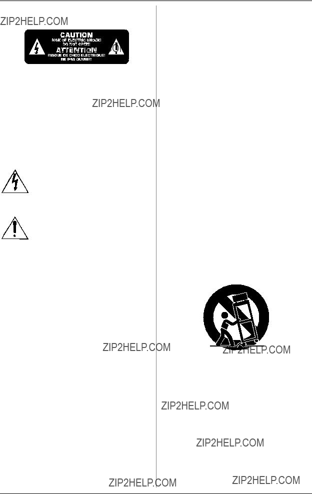
CAUTION: To reduce the risk of electric shock, do not remove the cover (or back). No
WARNING: The apparatus shall not be exposed to dripping or splashing and that no objects filled with liquids, such as vases, shall be placed on the apparatus.
This symbol, wherever it appears, alerts you to the presence of uninsulated dangerous voltage inside the
This symbol, wherever it appears, alerts you to important operating and maintenance instructions in the accompanying literature. Please read the manual.
IMPORTANT SAFETY INSTRUCTIONS:
1)Read these instructions.
2)Keep these instructions.
3)Heed all warnings.
4)Follow all instructions.
5)Do not use this apparatus near water.
6)Clean only with dry cloth.
7)Do not block any ventilation openings. Install in accordance with the manufacturer???s instructions.
8)Do not install near any heat sources such as radiators, heat registers, stoves, or other apparatus (including amplifiers) that produce heat.
9)Do not defeat the safety purpose of the polarized or
10)Protect the power cord from being walked on or pinched particularly at plugs, convenience receptacles, and the point where they exit from the apparatus.
11)Only use attachments/accessories specified by the manufacturer.
12)Use only with the cart, stand, tripod, bracket, or table specified by the manufacturer, or sold with the apparatus. When a cart is used, use caution when moving the cart/ apparatus combination to avoid injury from
13)Unplug this apparatus during lightning storms or when unused for long periods of time.
14)Refer all servicing to qualified service personnel. Servicing is required when the apparatus has been damaged in any way, such as power supply cord or plug is damaged, liquid has been spilled or objects have fallen into the apparatus, the apparatus has been exposed to rain or moisture, does not operate normally, or has been dropped.
15)CAUTION - These service instructions are for use by qualified service personnel only. To reduce the risk of electric shock do not perform any servicing other than that contained in the operation instructions unless you are qualified to do so.
2

 FADER
FADER  ROTARY BCR2000
FOREWORD
Dear Customer,
welcome to the team of BEHRINGER users, and thank you very much for expressing your confi- dence in us by pur- chasing the
Writing this foreword for you gives me great pleasure, because it represents the culmi- nation of many months of hard work delivered by our engineering team to achieve a very ambitious goal: to present two outstanding USB MIDI CONTROLLERS. Due to their extreme flexibility they can be used as a
central control unit with USB/MIDI interface as well as for mere MIDI control applications. The task of designing our new
It is our philosophy to share our enjoyment with you, because you are the most important member of the BEHRINGER team. With your highly competent suggestions for new products you???ve made a significant contribution to shaping our company and making it successful. In return, we guarantee you uncompromising quality as well as excellent technical and audio properties at an extremely reasonable price. All of this will enable you to give free rein to your creativity without being hampered by budget constraints.
We are often asked how we manage to produce such high- quality devices at such unbelievably low prices. The answer is quite simple: it???s you, our customers! Many satisfied customers mean large sales volumes enabling us to get better purchasing terms for components, etc. Isn???t it only fair to pass this benefit on to you? Because we know that your success is our success too!
I would like to thank all of you who have made the
My friends, it???s been worth the effort!
Thank you very much,
Uli Behringer
TABLE OF CONTENTS
3

 FADER
FADER  ROTARY BCR2000
+Damaged equipment should NEVER be sent directly to be performed. Adjusting these parameters, you can control various us. Please inform the dealer from whom you acquired functions of external (hardware or software) equipment in real the unit immediately as well as the transportation time. For example, countless software mixers, sound generators company from which you took delivery of the unit. or effects can be remotely controlled. With these software Otherwise, all claims for replacement/repair may be applications, you are dealing with simulations of ???real??? equipment

 FADER
FADER  ROTARY BCR2000
sset filter frequency to CC 05
sset filter resonance to CC 06 (receive)
sset volume to CC 07 (receive)
To get detailed information on how to assign them, please refer to chapter 4.3.2 ???Programming in the EDIT mode??? on page 13.
Now, define in the
sAssign the push encoder 1 CC 05 to filter frequency control via dial rotation.
sAssign the push encoder 2 CC 06 to filter resonance control via dial rotation.
sAssign the push encoder 3 CC 07 to volume control via dial rotation.
How do I wire the
Several classic examples can be found in the explanations of different operating modes (see chapter 4.1 ???The Operating Modes???). Basically, the following applies:
sIf you want to control hardware MIDI equipment, use the MIDI connectors.
sTo control software MIDI equipment, you can either use the MIDI connectors on your
sTo remotely control both hardware and software equipment, several combination modes are available. These are explained in chapter 4.1.
What kinds of equipment can I control with the
You can basically control any device supporting the MIDI format. Both hardware and software MIDI devices are controlled exactly the same. The only difference is in the wiring.
Here are a couple of suggestions on how you can use your
sEditing sound parameters of (virtual) synthesizers, sound samplers, GM/GS/XG sound generators
sControlling parameters on effects equipment/software
sRemotely controlling software mixers (volume, panorama, equalizers etc.)
sRemotely controlling transport functions (playback, forward, stop etc.) on sequencers, hard disk recorders, drum computers etc.
sUsing BCF2000 faders as drawbar control for virtual or digital organ expanders
sControlling
sLive control of volume and sound parameters on expanders
sTriggering (i.e. playing live) short samples, drum loops, shouts, effects etc.
sRemotely controlling groove boxes, step sequencers, MIDI generators (such as arpeggiators etc.), DJ software and other ???live??? software
sProgram changes and volume control on sound generators (just like on a master keyboard)
sLikewise, applicable to band keyboardists, solo entertainers, organists, electronic music performers, DJs, sound engineers, home/project studio owners, theater technicians etc.
2.2 The MIDI standard
The MIDI standard (Musical Instruments Digital Interface) was developed in the early ???80s to make communication between equipment from different manufacturers possible. Over the years, the MIDI interface has become hugely popular; it has become a matter of fact that complete studios can be connected via MIDI.
At the center of any such network is at least one computer that controls peripheral equipment. You can use the
2.3 MIDI connections
The MIDI connections in the back of your
MIDI IN: Used for receiving MIDI data (parameter feedback, SysEx data), or to mix MIDI signals with the
MIDI OUT A/B: Data for controlling other MIDI equipment can be sent through the MIDI outputs.
+The
2.4 The MIDI format
Although your
Note messages:
Among keyboard hotshots, Note On and Note Off messages are among the essential MIDI messages. Playing MIDI instruments from a master keyboard or computer is only possible with these messages. The
Note On and Note Off messages have the following data format:
Table 2.1: Data format of Note On and Note Off messages
The value range for channel numbers is between 1 and 16; for data bytes it is 0 to 127. Even though Note Off messages are not really used by keyboarders anymore, the
Velocity corresponds to the key pressure, and therefore to the volume of a
+A note command can only be assigned to keys, footswitches and push functions of the encoder.

 FADER
FADER  ROTARY BCR2000
Control Change (CC):
Control Change Messages are some of the most ???powerful??? MIDI messages. Using them, a vast number of parameters and functions can be recalled and automated. Individual control elements (faders, rotary dials, keys etc.) can be assigned to CC messages on your
NRPN:
Additionally, controllers that have no standardized assignment can also be used, and can therefore be assigned according to no predetermined rule. These controllers are called NRPNs (Non- Registered Parameter Numbers). NRPNs are further subdivided into MSB (Most Significant Byte) and LSB (Least Significant Byte) in order to achieve a higher resolution. A lower resolution is particularly easy to observe during fader movement of a mixer, in which
Pitch Bend
The
After Touch
MIDI keyboards featuring After Touch can respond to varying key pressure even after you release the key (i.e. after the keystroke is over) and can send this data via MIDI. This function either reacts
MIDI Machine Control (MMC):
With MIDI Machine Control, you can assign transport functions of a sequencer or drum computer (e.g. start, stop, FFW/RWD) and locator points to individual keys with a permanently adjustable time position (locate, punch in/out points).
Program Change Messages and MIDI Bank Select:
Program change messages are used to recall programs/presets in MIDI devices connected to your
Running Status:
Because the MIDI interface is a serial data transmission format (meaning that its data is transmitted as a succession of individual data segments), it became apparent very quickly that it may not be fast enough. To avoid perceptible delays in the output of MIDI data, Running Status was designed. It suppresses the transmission of the status byte when the same MIDI messages are transmitted in succession. This means that, for example, during a continuous change of the data byte of a controller (e.g. volume), the status byte is only sent once. The only thing that is transmitted are the changes in the data byte. This goes on until another status byte is sent. 8 bits are saved for each message sent.
SysEx Dump:
The status byte notes the data type (SysEx); the first three data bytes are a manufacturer ID, so that when you have a large MIDI network, you can still ???talk??? to the correct MIDI device.
To make using several identical
3. CONTROL ELEMENTS AND
CONNECTIONS
In this chapter, we will describe various control elements of your
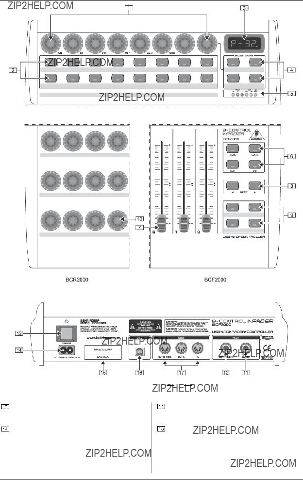
The 8 infinitely variable push encoders are used to send MIDI data. They have two functions (turn and press) that can be assigned to different MIDI commands.
Each of these 16 keys can send one MIDI command.
The
Using the ENCODER GROUP keys, four
These LEDs indicate the following:
MIDI IN, OUT A and OUT B illuminate if MIDI data flows through the respective connectors.
USB Mode illuminates if a USB connection to a computer is active (your computer must be on).
The FOOT SW LEDs illuminate if the footswitch is pressed.
FOOT CTRL LED (BCF2000 only) illuminates when the footcontroller is actuated (MIDI data is sent).
Permanently fixed functions are assigned to this key section:
STORE saves presets.
LEARN gets you to the LEARN mode.
EDIT gets you to the EDIT mode.
Using the EXIT key, you exit a programming level (edit mode/ global setup). Use it also to cancel a store or copy procedure.
The eight
Using the PRESET keys, 32 presets can be recalled. The preset number is shown in the display.
These four keys can be assigned to any MIDI command of your choice.
The 24 infinitely variable rotary controls (encoders) of the BCR2000 can be programmed to send MIDI control commands. The LED circle show the current value.
These are the SWITCH connectors for connecting a footswitch. Its polarity is automatically detected. On the BCR2000, the first connector (SWITCH 1) can also be used to connect a double footswitch with stereo jacks. In this case, SWITCH 2 must remain unused.
 FADER
FADER  ROTARY BCR2000
Fig. 3.1: The control surface of the
Fig.3.2: The back of the BCF2000 (control elements  to
to  coincide with the BCR2000)
CONTROLLER connector (BCF2000 only). Here, you can connect an expression pedal that can be used for controlling assignable MIDI data.
The POWER switch turns your
+Please keep in mind: The POWER switch does not fully disconnect your
The connection to the mains is established using a standard connection socket. A matching cable is included in the shipment.
SERIAL NUMBER. Please take the time to fill out and return the warranty card within 14 days after the date of purchase to benefit from our extended warranty. The serial number is located on the top side of your REV2496. You can also register online at www.behringer.com.

 FADER
FADER  ROTARY BCR2000
Fig. 3.3: The footswitch connectors on the BCR2000
The USB connector is used for connecting to a computer with a compatible USB input.
These are the MIDI connectors of your
MIDI THRU.
4. OPERATION
4.1The operating modes
Depending on how you want to use your
You can use it as a pure USB controller for your computer applications (software mixers, sequencers, soft synths, VST- effects etc.), as a
sKeep the EDIT key pressed, and press the STORE key at the same time.
sYou are now in the global setup menu and you can let go of both keys.
sNow, select an operating mode by turning the PUSH encoder 1. You can select USB modes
sTo exit global setup, please press the EXIT key.
+The settings made in the global setup menu are automatically stored and do not have to be separately saved.
The USB connection is briefly interrupted if you switch within a USB mode, or when you switch from a USB mode to a stand- alone mode and vice versa.
If a USB connection is made or lost while your
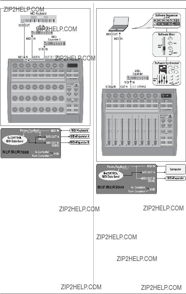
4.1.1 USB modes
USB mode
Fig. 4.1: Routing and use in USB mode 1
In USB mode 1, the
All MIDI ports of the

 FADER
FADER  ROTARY BCR2000
Fig. 4.2: Routing and use in USB mode 2
Your
Fig. 4.3: Routing and use in USB mode 3
This is surely the most often used ???standard mode??? with computer applications.
This setting is optimal for controlling software while all MIDI connectors are used as a
The

 FADER
FADER  ROTARY BCR2000
Fig. 4.4: Application in USB mode 4 (expanded)
Fig. 4.5: Routing in USB mode 4
This operating mode should be selected if you want to couple two
4.1.2
The
 FADER
FADER  ROTARY BCR2000
Stand
Fig. 4.6: Routing and use in
Stand
Fig. 4.7: Routing and use in
Say you want to control just one sound generator from your
 FADER
FADER  ROTARY BCR2000
Stand
Fig. 4.8: Routing and use in
In this mode, MIDI data from the BCF2000/BCR2000 is mixed with the data coming in at the MIDI input (merge function), but is exported exclusively on output A. Only control data of the
This way, you can control two MIDI devices from your
If you want to
If additional MIDI inputs are needed, then external MIDI merge boxes must be used. For example, if your sound module only has one MIDI IN connector, and you want to control if from several MIDI controllers and from a keyboard, you will need a
If additional MIDI outputs are required, you will need external thru boxes. With more complex MIDI setups, thru boxes are preferred to using longer thru chains to prevent data transmission problems.
If you don???t require the response function during software control, you can connect as many BCF2000/BCR2000s as you want per MIDI. The last
Stand Alone Mode
Fig. 4.9: Routing and use in
The Stand Alone mode
Connect the MIDI output on the MIDI interface of your computer to the MIDI IN input on the
Important information about
With the wiring examples shown here, the parameter values of the controlled devices can be shown on the

 FADER
FADER  ROTARY BCR2000
Parameter feedback is enabled in all
Your
4.2 ???Play??? mode menu
The Play mode menu is the highest menu level in the
Display:
After switching on the unit, the current system software version is briefly displayed. Value changes are shown when using one of the control elements, provided that they have been activated.
Control elements:
You can use several keys, encoders and faders simultaneously and send their MIDI data. The classification of MIDI data types is explained in chapter 4.4. According to its assigned MIDI data type, each control element shows the current parameter value in the corresponding LED or LED ring.
The position of the faders changes automatically as soon as you choose another preset or during incoming parameter messages.
LED display:
The encoder LED ring displays or the status LEDs of the buttons change automatically when running controller recordings in a sequencer, provided, of course, all connections have been made correctly, the correct operating mode is enabled and the software sequencer supports sending parameter values.
Button illumination varies according to the controller mode: if a button is in ???Toggle on??? mode, the button LED illuminates as soon as the button is pressed. Only when you press the button once again, the LED goes out. If a button is in ???Toggle off??? mode, the corresponding LED will be lit only for the time the button is pressed.
The performance of the control elements, the display and the LED displays can be individually set up and is explained in chapter 4.3 ???Programming???.
4.2.1 Selecting a preset
sSelect a preset with the PRESET button  . The new preset number is indicated in the display.
sAlternatively, you may select a preset by pressing and holding down the preset button while moving one of the push encoders  .
.
sAs soon as you release the PRESET button, the new preset is active.
4.2.2Copy/store presets
sPress the STORE button to save a preset. The button LED starts to flash.
sSelect a memory number using the PRESET buttons or by holding down one of the PRESET buttons while moving a push encoder at the same time. The new preset number flashes in the display.
sBy pressing STORE again, the STORE LED and the display stop flashing.
sIf you want to overwrite the current preset, press the STORE button twice (step 2 can be cancelled).
sCancel the store procedure by pressing the EXIT button.
We deliberately did not include an autostore function. That way, you can assign a new MIDI control to a control element without changing the current preset. If you want to restore a preset, just select another preset briefly and again return to editing. Now, the old data has been restored.
4.2.3 Copying encoder groups
With this function you are able to copy an entire encoder group within a preset. This saves a lot of programming effort if all encoder groups within a preset consist of the same basic functions (e.g. MIDI channel, CC number for turn and push function).
sPress the encoder group button of the group you want to copy.
sPress STORE; the STORE button LED flashes.
sNow select the destination encoder group. The destination encoder button LED flashes.
sPress STORE again, the STORE button LED is no longer lit.
sCancel the store procedure at any time by pressing EXIT.
+To permanently store encoder group settings, carry out the preset store function as explained in chapter 4.2.2.
+To copy an encoder group into a different preset, you have to copy an entire preset! After that, you can copy or rearrange the encoder groups in the new preset as described above.
4.3Programming
4.3.1 The LEARN function
The easiest way to assign MIDI functions to individual control elements is to use the LEARN function. Here, the MIDI data is assigned remotely. For example, MIDI data sent from a MIDI sequencer to your
With LEARN, not only CC, NRPN and note commands can be received but almost any type of MIDI data, including short SysEx strings.
sPress and hold the LEARN button while operating any control element. This can be a fader (BCF2000 only), an encoder BCR2000 only), a PUSH encoder, button, footswitch or sustain pedal (BCF2000 only). The control element is shown in the display (e.g. E 24 or Fd 8).
+When using push encoders, select an encoder group beforehand. In addition, you have to differentiate between turn and push function.
sNow, release the LEARN button. The
sStart transmitting MIDI data from your sequencer. As soon as the data is received by the BCF2000/BCR2000, it is shown in the display.
sAfter correct data transmission, the display shows ???GOOD??? or ???bAd??? if wrong, faulty or too extensive data has been sent.
sTo leave or cancel LEARN, press the EXIT button.
4.3.2 Programming in EDIT mode
Various types of MIDI commands (Pitchbend, After Touch, MMC etc.) are assigned to the individual control elements in EDIT mode.
sTo activate the EDIT mode, press and hold the EDIT button and operate a control element. This can be a fader, sustain pedal (BCF2000 only), an encoder (BCR2000 only), a push encoder, a button or footswitch. The control element is indicated in the display (e.g. E 24 or Fd 8).
+When using push encoders, select an encoder group beforehand. In addition, you have to differentiate between turn and push function.
 FADER
FADER  ROTARY BCR2000
sRelease EDIT; you are now in the EDIT mode.
sUsing the push encoders, you can now assign MIDI commands to the selected control element. You will find all possible MIDI function in tables 4.1 and 4.2, including all accompanying explanations.
sIf you want to assign MIDI data to additional control elements, just press and hold the EDIT button and move one of the control elements. Now, let go of both controls and use the push encoders to assign a function to it (see tables 4.1 and 4.2).
sTo leave the EDIT mode, press EXIT.
+Initially, all settings made here are stored temporarily! If you intend to store them in a preset, please see chapter 4.2.2.
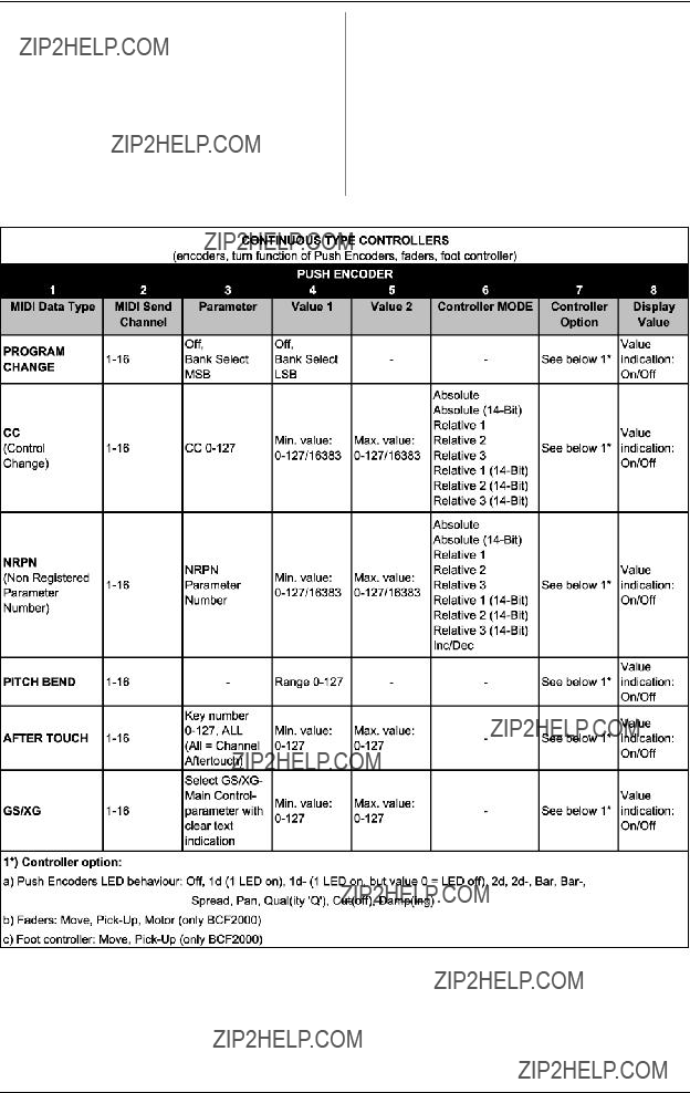
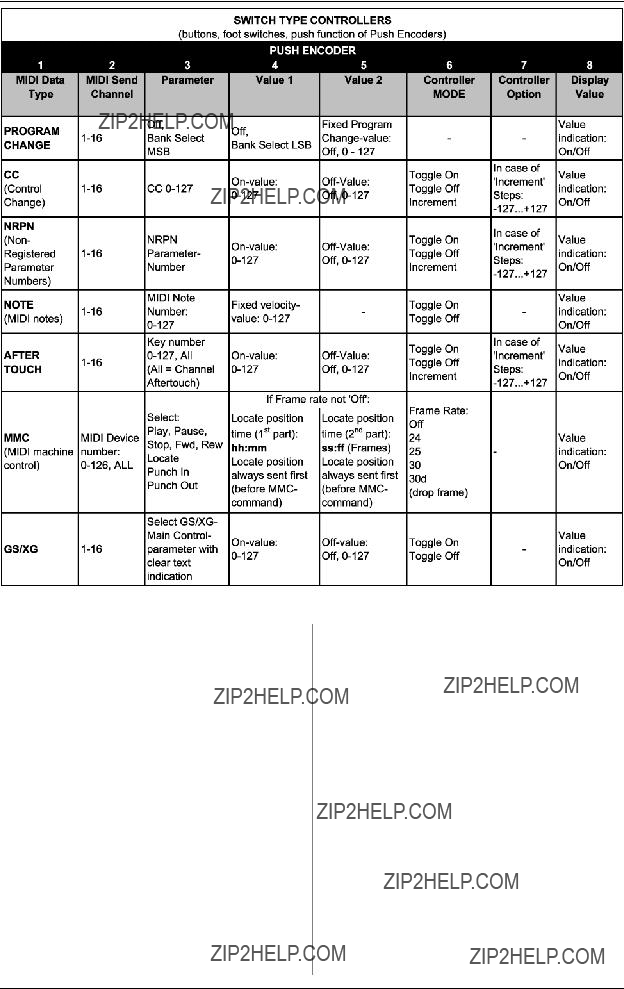
The detailed EDIT functions are described in the following two tables. With the assignable control elements, we differentiate between CONTINUOUS and SWITCH types.
s
s
Tab. 4.1: Assignment of the push encoders in EDIT mode (CONTINUOUS types)
 FADER
FADER  ROTARY BCR2000
Tab. 4.2: Assignment of the push encoders in EDIT mode (CONTINUOUS types)
Table explanation:
All settings in the EDIT mode are made by turning the push encoders. Pressing the push encoder displays its current value. In addition, the setting options depend on whether the selected control element is a SWITCH type or CONTINUOUS type.
In the EDIT mode, Push Encoder 1 selects (by turning) the type of command assigned to a control element.
With Push Encoder 2, select a MIDI channel through which that control element???s data is sent.
Push Encoders 3 - 5 set parameters and values for the selected MIDI type. They vary depending on the MIDI function. More details about this subject can be found later in this chapter.
Push Encoder 6 (Controller Mode) selects how the previously selected control element behaves, depending on whether it is a SWITCH or a CONTINUOUS type.
Relative
+The classic controler mode for most applications is ???absolute???. All other modes have to be supported by the MIDI software or the device to be controlled.
Using Push Encoder 7, you can adjust how control elements display information. Depending on whether you are dealing with an encoder, push encoder, fader or foot pedal, there are different options available:
LED display of the push encoders:
OFF The LED circle remains off.
1d (1 digit): Only one LED lights up (standard setting).
1d- The LED circle operates similar to ???1d???, but when the value is 0, no LED lights up.
2d The display of the LED circles occurs in two stages. If you slowly turn the encoder from left to right, at first only one LED lights up, and then the next LED lights up while the previous LED goes out, and so on. This way, even the slightest value changes can be accurately represented.

 FADER
FADER  ROTARY BCR2000
Bar- Just like bar display, but when the value is 0, no LED
Encoder LED display (BCR2000):
1d (1 digit): Only one LED lights up at a time (standard setting).
1d- The LED circle operates similar to ???1d???, but when the value is 0, no LED lights up.
Fader functions (BCF2000):
Move If you move the fader by hand, it sends a new value directly. In doing so, jumps in the parameter value may occur if the current value doesn???t correspond to the fader position. This can sometimes happen because in this mode parameter feedback doesn???t cause fader movement.
Foot controller function:
Move The pedal immediately sends value changes. Value jumps may result.
The Toggle Off mode corresponds to a
The Increment option only works for buttons, and only on CC, NRPN and after touch command types. This mode lets you gradually increase the controller value with each new keystroke. Set up increment size using encoder 7. If you repeatedly press a
button, the value sent will be increased each time by the preset amount selected here. If increment size is set to ???10,??? values 0, 10, 20, 30 ... 110, 120, 0, 10 and so on will be successively sent one after another. You can also enter negative values (e.g.
The value display activated using Push Encoder 8 is identical for switch and continuous elements. If this value display is active, the current value is indicated in the
4.4 MIDI messages
Program Change:
With the encoders 3 and 4 you can select bank numbers. If a MIDI device contains more than 128 presets/programs, first a bank change command has to be sent. Even though this is a controller command, it has to be sent before the program change (and is therefore adjustable) since it is linked to the preset change. If the bank select message is not needed, simply select ???off???.
Encoder 5 selects the program number. If the selected control element is a control dial (continuous type), the program number is directly selected when turning the dial. Pressing the switch directly selects the assigned program number. This can be useful if you always want to start from the same preset.
Control Change CC:
A control change consists of a controller number and its respective value. Encoder 3 sets the controller number. With buttons, different values can be sent when pressing and releasing (to be set with encoders 4 and 5). This function is useful if fixed parameter settings are to be sent.
With faders and control dials (continuous type), the value range can be determined by using encoders 4 (minimum value) and 5 (maximum value).
+Alternatively, you can invert the value scale by assigning 127 as the minimum value and 0 as maximum value (scale inversion). A classic application is the draw bar control of virtual or digital organs or organ expanders. If assigning controller 7 (volume) to the faders of the BCF2000 this way, the signal becomes quieter when moving up the fader. Moving down the fader is similar to moving out the draw bars, and the volume increases.
NRPN:
A NRPN is needed if none of the 127 standardized controller numbers are available for a certain function.
Encoder 3 selects the parameter number. For assigning mixer faders, we recommend the high resolution (???Absolute 14 bit???), provided that the control hardware/software supports it.
Note:
Of course, a note can only be assigned to one SWITCH element. The note is set with encoder 3. Note C3 (C key) corresponds with note number 60. Encoder 4 sets the note velocity (note volume).
Pitch Bend:
Pitch bend is assignable to only one CONTINUOUS element. Since this is a type of command with its own status byte, selecting a MIDI channel (Encoder 2) and Range (Encoder 4) is sufficient.
After Touch:
Normally, ???ALL??? is selected here. This means that After Touch affects all notes equally (???Channel Pressure???). If you want to use a polyphonic After Touch (???Key Pressure???), the single note on which After Touch should have an effect can be selected using encoder 3. Since this process is only supported by a few tone generators, channel After Touch will be best most of the time. When a switch element has been selected, an ???on??? and ???off??? value

 FADER
FADER  ROTARY BCR2000
can also be set (release dynamic). Therefore, you can limit the modulation range (FX depth) using After Touch.
MMC:
MIDI Machine Control data is only assignable to button elements.
Encoder 4 (Value 1) sets ???Locate Time??? hour and minute values, while encoder 5 (Value 2) sets seconds and frames. The Locate Position is always sent before the MMC command. We therefore have the following
If the ???Locate??? parameter has been selected, the sequencer or hard drive recorder always jumps to the set position. If ???Play??? has been selected as the parameter (for a button), the sequencer always starts from the set locator point as soon as the button is pressed. ???Rewind??? always begins at the chosen locator point. Select the frame rate with encoder 6: 24, 25, 30
GS/XG:
Encoder 3 directly selects the most important ???Main Control??? parameters. The display indicates them as a (shortened) text (table 4.2). In this case, these are CCs or NRPNs (no SysEx data).
Table 4.3: GS/XG Parameter Main Controls
Encoders 4 and 5 let you confine or invert each controllers??? value range.
4.5 Settings in the global setup menu
Settings that have an effect on all presets are made in the global setup menu.
sKeep the EDIT key pressed and at the same time press the STORE key.
sYou are now in the global setup menu, and can let go of both keys.
sNow, turn the push encoders 1 to 8 to get the desired setting. This is how the push encoders are allocated:
Table 4.4: Push encoder allocation in global setup menu
sTo exit the global setup menu, press EXIT.
+The settings in the global setup menu take effect immediately and do not have to be separately stored.
Operating Mode:
The operating modes are described in chapter 4.1. You can select USB modes
Global RX Channel:
The
Footswitch type:
Because there are different kinds of footswitches (depending on their switching behavior), the polarity of the footswitch connector can be set (normal/inverted), or it can be automatically detected during power startup (auto recognition).
Start Preset Number:
Each of the 32 presets can be selected as the startup preset. Additionally, with the ???Last??? function, at startup you have the option to always load the preset that was used last.
Device ID Number:
You should change the ID number settings only if you work with several BCF2000s or BCR2000s at the same time, and problems with recognizing the correct device start occurring during a SysEx Dump procedure.
+Please keep in mind that SysEx Dumps can only be received at the device number to which they were sent!
SysEx Dump Select:
Turning push encoder 6 lets you select between the current preset (single) or the entire memory contents of the 32 presets (all) should be sent as a SysEx dump. One press on encoder 6 triggers the dump.
To receive a SysEx dump, you don???t have to change any settings on your equipment. If you send a single preset to the
+WARNING: If you send an
sTo cancel a SysEx dump, press the EXIT key.
MIDI Data Interval:
This is where you adjust the data transmission rate. This setting only has an effect on MIDI data packs such as SysEx dumps and not on controlling of MIDI commands (they are carried out in real time anyway). The transmission rate is adjustable in milliseconds.
4.6 Additional functions
Temporary ???Local Off???:
???Local Off??? means that when you move a control element on the
Deviations between the position of a control element and the current parameter value can occur if no parameter feedback is being sent while a value is being changed in the software (e.g. mixer automation).
sPress the EXIT key and keep it pressed.
sMove the desired control element until you get the correct value.
sLet go of the EXIT key. The control element can now be moved again.
 FADER
FADER  ROTARY BCR2000
Panic Reset:
This function resets the most important MIDI data to their factory settings.
sPress EDIT and keep it pressed.
sNow press EXIT. The reset is performed as soon as you press EXIT. ???PAnC??? (for ???Panic???) appears in the display.
sAs soon as the reset is over, your
Data Request:
Current value settings of the MIDI device connected to your
sPress the LEARN key while the EDIT key is kept pressed. The request takes place, and the
Snapshot Send:
A Snapshot Send lets you send all current controller values in order to transmit the
sPress the ??? PRESET??? key while the EDIT key is kept pressed. The
Single Preset Dump:
In addition to the SysEx Dump function in the global setup menu, the following key combination lets you send all settings of the current presets:
sPress the ???PRESET  ??? key while the EDIT key is kept pressed.
sIf you want to cancel the dump, press the EXIT key.
+Snapshot Send and Single Preset Dump differ in the kind of data that is being sent: With Snapshot Send, only current control values are transmitted in order to synchronize them with the connected MIDI device. With Single Preset Dump, the entire contents of the current preset including the current control assignments are sent. With this function, you can easily archive certain presets, or swap them with other
Motor Off Function (BCF2000):
The BCF2000 fader motors can be temporarily disengaged. To do that, one or several fader(s) is/are assigned a key that disengages the fader???s motor for the duration of the keystroke. All 20 programmable keys (  and
and  ) are available.
sPress the EDIT key and keep it pressed.
sMove the fader(s) whose motors you wish to disengage.
sPress the key to which you want to assign the
sExit with EXIT.
+The MIDI command assigned to a key remains preserved. This way, that MIDI function can be used simultaneously with the fader motor being disengaged when the key is pressed.
 FADER
FADER  ROTARY BCR2000
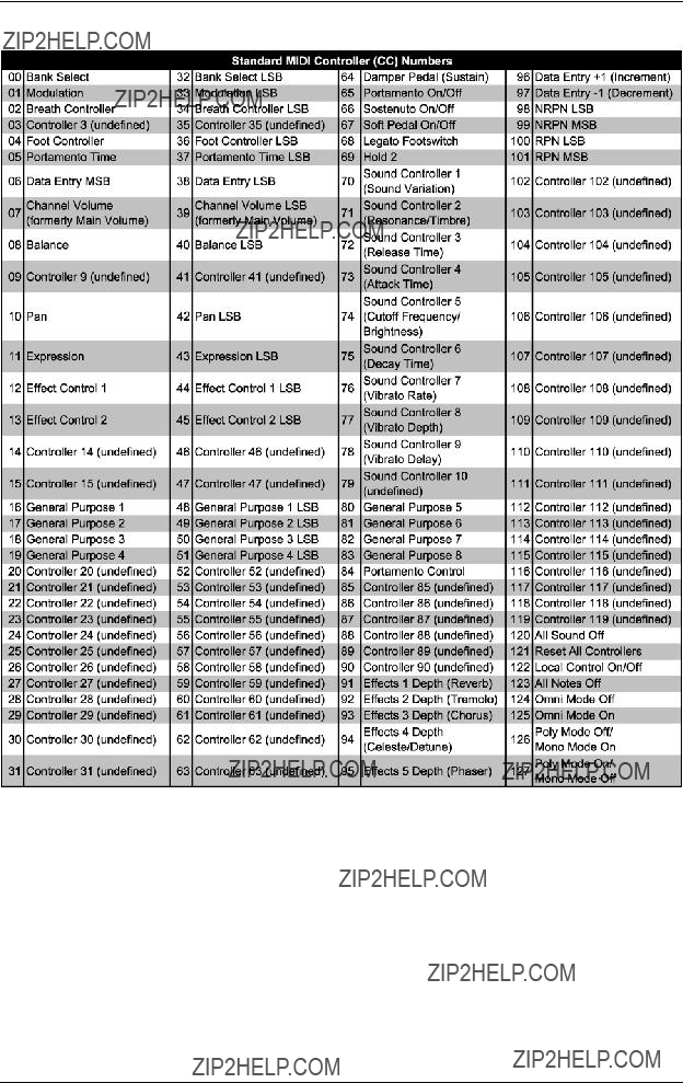
5. APPENDIX
Table 5.1: Standard MIDI Controller

 FADER
FADER  ROTARY BCR2000
Table 5.2: GS/XG Parameter Main Controls
Table 5.3: MIDI note number assignment
6. SPECIFICATIONS
USB INTERFACE
TypeFull-speed 12 MBit/sec.
USB MIDI
MIDI INTERFACE
Type5-pin DIN connectors IN, OUT A,
OUT B/THRU
CONTROL ELEMENTS
BCF2000
BEHRINGER is constantly striving to manintain the highest professional standards. As a result of these efforts, modifications may be made from time to time to existing products without prior notice. Specifications and appearance may differ from those listed or illustrated.
 FADER
FADER  ROTARY BCR2000
7.WARRANTY
??1 WARRANTY CARD/ONLINE REGISTRATION
To be protected by the extended warranty, the buyer must complete and return the enclosed warranty card within 14 days of the date of purchase to BEHRINGER Spezielle Studiotechnik GmbH, in accordance with the conditions stipulated in ?? 3. Failure to return the card in due time (date as per postmark) will void any extended warranty claims. Based on the conditions herein, the buyer may also choose to use the online registration option via the Internet (www.behringer.com or www.behringer.de).
??2 WARRANTY
1.BEHRINGER (BEHRINGER Spezielle Studiotechnik GmbH including all BEHRINGER subsidiaries listed on the enclosed page, except BEHRINGER Japan) warrants the mechanical and electronic components of this product to be free of defects in material and workmanship for a period of one (1) year* from the original date of purchase, in accordance with the warranty regulations described below. If the product shows any defects within the specified warranty period that are not excluded from this warranty as described under ?? 4, BEHRINGER shall, at its discretion, either replace or repair the product using suitable new or reconditioned parts. In the case that other parts are used which constitute an improvement, BEHRINGER may, at its discretion, charge the customer for the additional cost of these parts.
2.If the warranty claim proves to be justified, the product will be returned to the user freight prepaid.
3.Warranty claims other than those indicated above are expressly excluded.
??3 RETURN AUTHORIZATION NUMBER
1. To obtain warranty service, the buyer (or his authorized dealer) must call BEHRINGER (see enclosed list) during normal business hours BEFORE returning the product. All inquiries must be accompanied by a description of the problem. BEHRINGER will then issue a return authorization number.
2.Subsequently, the product must be returned in its original shipping carton, together with the return authorization number to the address indicated by BEHRINGER.
3.Shipments without freight prepaid will not be accepted.
??4 WARRANTY REGULATIONS
1.Warranty services will be furnished only if the product is accompanied by a copy of the original retail dealer???s invoice. Any product deemed eligible for repair or replacement under the terms of this warranty will be repaired or replaced.
2.If the product needs to be modified or adapted in order to comply with applicable technical or safety standards on a national or local level, in any country which is not the country for which the product was originally developed and manufactured, this modification/adaptation shall not be considered a defect in materials or workmanship. The warranty does not cover any such modification/adaptation, irrespective of whether it was carried out properly or not. Under the terms of this warranty, BEHRINGER shall not be held responsible for any cost resulting from such a modification/adaptation.
3.Free inspections and maintenance/repair work are expressly excluded from this warranty, in particular, if caused by improper handling of the product by the user. This also applies to defects caused by normal wear and tear, in particular, of faders, crossfaders, potentiometers, keys/buttons, tubes and similar parts.
4.Damages/defects caused by the following conditions are not covered by this warranty:
simproper handling, neglect or failure to operate the unit in compliance with the instructions given in BEHRINGER user or service manuals.
sconnection or operation of the unit in any way that does not comply with the technical or safety regulations applicable in the country where the product is used.
sdamages/defects caused by force majeure or any other condition that is beyond the control of BEHRINGER.
5.Any repair or opening of the unit carried out by unauthorized personnel (user included) will void the warranty.
6.If an inspection of the product by BEHRINGER shows that the defect in question is not covered by the warranty, the inspection costs are payable by the customer.
7.Products which do not meet the terms of this warranty will be repaired exclusively at the buyer???s expense. BEHRINGER will inform the buyer of any such circumstance. If the buyer fails to submit a written repair order within 6 weeks after notification, BEHRINGER will return the unit C.O.D. with a separate invoice for freight and packing. Such costs will also be invoiced separately when the buyer has sent in a written repair order.
?? 5 WARRANTY TRANSFERABILITY
This warranty is extended exclusively to the original buyer (customer of retail dealer) and is not transferable to anyone who may subsequently purchase this product. No other person (retail dealer, etc.) shall be entitled to give any warranty promise on behalf of BEHRINGER.
?? 6 CLAIM FOR DAMAGES
Failure of BEHRINGER to provide proper warranty service shall not entitle the buyer to claim (consequential) damages. In no event shall the liability of BEHRINGER exceed the invoiced value of the product.
??7 OTHER WARRANTY RIGHTS AND NATIONAL LAW
1.This warranty does not exclude or limit the buyer???s statutory rights provided by national law, in particular, any such rights against the seller that arise from a legally effective purchase contract.
2.The warranty regulations mentioned herein are applicable unless they constitute an infringement of national warranty law.
* Customers in the European Union please contact BEHRINGER Germany Support for further details.
Technical specifications and appearance subject to change without notice. The information contained herein is correct at the time of printing. WINDOWS??, MAC OS X?? as well as the names of companies, institutions or publications pictured or mentioned and their respective logos are registered trademarks of their respective owners. Their use neither constitutes a claim of the trademarks by BEHRINGER?? nor affiliation of the trademark owners with BEHRINGER??. BEHRINGER?? accepts no liability for any loss which may be suffered by any person who relies either wholly or in part upon any description, photograph or statement contained herein. Colours and specification may vary slightly from product. Products are sold through our authorised dealers only. Distributors and dealers are not agents of BEHRINGER?? and have absolutely no authority to bind BEHRINGER?? by any express or implied undertaking or representation. No part of this manual may be reproduced or transmitted in any form or by any means, electronic or mechanical, including photocopying and recording of any kind, for any purpose, without the express written permission of BEHRINGER Spezielle Studiotechnik GmbH. BEHRINGER?? is a registered trademark.
ALL RIGHTS RESERVED.?? 2004 BEHRINGER Spezielle Studiotechnik GmbH.
BEHRINGER Spezielle Studiotechnik GmbH,
47877
Tel. +49 2154 9206 0, Fax +49 2154 9206 4903