Owner's Manual for Vehicle
Owner's Manual for Vehicle

325i
325xi
Congratulations, and thank you for choosing a BMW.
Thorough familiarity with your vehicle will provide you with enhanced control and security when you drive it. Therefore we have one request:
Please take the time to read this Owner's Manual and familiarize yourself with the information that we have compiled for you before starting off in your new BMW. The manual contains important data and instructions intended to assist you in obtaining maximum satisfaction from your BMW's unique array of advanced technical fea- tures. It also contains information on vehicle maintenance designed to enhance operating safety while simultaneously helping you to maintain your BMW's value throughout an extended service life. For additional information refer to the supple- mental manuals.
This Owner's Manual should be considered a permanent part of this vehicle. It should stay with the vehicle when sold to provide the next owner with important operating, safety and maintenance information.
We wish you an enjoyable driving experience.
BMW AG

4 Notes
About this Owner's Manual
Additional sources of information Symbols used
We have made every effort to ensure that you are able to find what you need in this Owner's Manual as quickly as possible. The fastest way to find spe- cific topics is by using the detailed index at the end. If you wish to gain an initial overview of your vehicle, you will find this in the first chapter.
Should you wish to sell your BMW at some time in the future, please remem- ber to hand over this Owner's Manual to the new owner; it is an important part of the vehicle.
?? 2003 Bayerische Motoren Werke Aktiengesellschaft
Munich, Germany
Reprinting, including excerpts, only with the written consent of BMW AG, Munich. Order No. 01 41 0 157 605
US English VIII/03
Printed in Germany
Printed on environmentally friendly paper, bleached without chlorine, suitable for recycling.
If you have any additional questions, your BMW center will be glad to advise you.
You can find more information about BMW, for example on its technology, on the Internet at www.bmw.com.
Indicates precautions that must be followed precisely in order to avoid the possibility of personal injury
and serious damage to the vehicle.
Contains information that will assist you in gaining the optimum
benefit from your vehicle and enable you to care more effectively for your vehicle.
Refers to measures that can be taken to help protect the environ-
ment.
 Marks the end of a specific item of information.
 Indicates special equipment, coun-
Vehicle Memory, Key Memory, refer to page 61. Identifies func-
tions that can be specifically adapted for a particular key or vehicle. These adjustments can be performed either by yourself or by your BMW center.

Notes
5
Your individual vehicle
On purchasing your BMW, you have decided in favor of a model with individ- ualized equipment and features. This Owner's Manual describes all models and equipment that BMW offers within the same group.
We hope you will understand that equipment and features are included that you might not have chosen for your vehicle. You can easily identify any dif- ferences with the aid of the asterisk  used to identify all optional equipment and accessories.
If your BMW features equipment, such as a car radio or telephone, which is not described in this Owner's Manual, sup- plementary Owner's Manuals are enclosed. We ask you to read these manuals as well.
Status at time of printing
BMW pursues a policy of continuous, ongoing development designed to ensure that our vehicles continue to embody the highest quality and safety standards combined with advanced,
For your own safety
Fuels
Use unleaded gasoline only. Fuels containing up to and including
10% ethanol or other oxygenates with up to 2.8% oxygen by weight ??? that is, 15% MTBE or 3% methanol plus an equivalent amount of
Failure to comply with these recom- mendations may result in unscheduled maintenance.
Obey all applicable safety rules when you are handling gasoline.<

6 Notes
Maintenance and repair
Advanced technology, e.g. the use of modern materials and high-
performance electronics, requires spe- cially adapted maintenance and repair methods. Therefore, only have corre- sponding work on your BMW carried out by a BMW center or a workshop that works according to BMW repair procedures with correspondingly trained personnel. If work is carried out improperly there is a danger of conse- quential damage and the related safety risks.<
Parts and accessories
Important safety information!
For your own safety, use genuine parts and accessories approved by BMW.
When you purchase accessories tested and approved by BMW and Original BMW Parts, you simultaneously acquire the assurance that they have been thor- oughly tested by BMW to ensure opti- mum performance when installed on your vehicle.
BMW warrants these parts to be free from defects in material and workman- ship.
BMW will not accept any liability for damage resulting from installation of parts and accessories not approved by BMW.
BMW cannot test every product made by other manufacturers to ascertain whether it can be used on a BMW safely and without risk to either the vehicle, its operation, or its occupants. Original BMW Parts, BMW Accessories and other products approved by BMW, together with professional advice on using these items, are available from all BMW centers.
Installation and operation of
wheels, suspension components, brake dust shields, telephones ??? including operation of any portable cellular phone from within the vehicle without using an externally mounted antenna ??? or trans- ceiver equipment such as a CB, walkie- talkie, ham radio or similar, may cause extensive damage to the vehicle, com- promise its safety, interfere with the vehicle's electrical system or affect the validity of the BMW Limited Warranty. See your BMW center for additional information.
Do not use key or remote control to lock doors or cargo area with anyone inside the vehicle. Refer to the Owner's Manual for more details.<
Maintenance, replacement, or repair of the emission control
devices and systems may be performed by any automotive repair establishment or individual using any certified auto- motive part.<
Symbol on vehicle parts
Indicates that you should consult the relevant section of this
Owner's Manual for information on a particular part or assembly.

Notes
Service and warranty
This manual is supplemented by a Ser- vice and Warranty Information Booklet for US models or a Warranty and Ser- vice Guide Booklet for Canadian mod- els.
We recommend that you read this pub- lication thoroughly.
Your BMW is covered by the following warranties:
>New Vehicle Limited Warranty
>Rust Perforation Limited Warranty
>Federal Emissions System Defect Warranty
>Federal Emissions Performance War- ranty
>California Emission Control System Limited Warranty.
Detailed information about these war- ranties is listed in the Service and War- ranty Information Booklet for US mod- els or in the Warranty and Service Guide Booklet for Canadian models.
7
Reporting safety defects
The following only applies to vehicles owned and operated in the US.
If you believe that your vehicle has a defect which could cause a crash or could cause injury or death, you should immediately inform the National High- way Traffic Safety Administration NHTSA in addition to notifying BMW of North America, LLC, P.O. Box 1227, Westwood, New Jersey
If NHTSA receives similar complaints, it may open an investigation, and if it finds that a safety defect exists in a group of vehicles, it may order a recall and remedy campaign. However, NHTSA cannot become involved in indi- vidual problems between you, your dealer, or BMW of North America, LLC.
To contact NHTSA, you may either call the Auto Safety Hotline
Contents
Overview
Cockpit 14 Instrument cluster 16
Indicator and warning lamps 18 Buttons in steering wheel* 22 Hazard warning triangle* 23
Refueling 24
Fuel specifications 25 Tire inflation pressure 25
Controls and features
Opening and closing:
Keys 30
Central locking system 30 Opening and closing ??? via the
remote control 31 Opening and closing ??? via the
door lock 34
Opening and closing ??? from the inside 35
Tailgate 35 Rear window 36 Cargo area 37 Alarm system* 38
Electric power windows 40 Glass sunroof, electric* 41
To adjust:
Safe seating position 44 Seats 45
Manual seat adjustment 45 Power seat adjustment* 47 Lumbar support* 47
Head restraints 48 Safety belts 48
Seat and mirror memory* 50 Seat heating* 51
Steering wheel 52 Mirrors 52

Contents
9
Controlling the climate for pleasant driving:
Air conditioning 96
Automatic climate control* 100
Interior conveniences:
Premium sound system* 105
Glove compartment 105
Storage compartments 106
Cellular phone* 107
Ashtray, front* 108
Ashtray, rear* 108
Socket 109
Contents
Owner service procedures
Replacement procedures:
Onboard tool kit 142 Windshield wiper blades 142 Lamps and bulbs 143 Changing a wheel 147
Run Flat tires* 150 Battery 151 Fuses 151
Giving and receiving assistance:
Receiving assistance 152
Technical data
Engine data 160 Dimensions 161 Weights 162 Capacities 163
Index
Everything from A to Z 166
12

13
Overview
Controls and features
Operation, maintenance
Owner service procedures
Technical data
Index
 Repairs Maintenance Controls Overview
Index Data

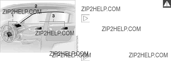
14 Cockpit

Cockpit
1 Parking lamps/Low beams 93
2 >Turn signal indicators 74
>Standing lamps 94
>High beams 94
>Headlamp flasher 74
>Computer 83
3Washer/wiper system/Rain sensor 75
4Hazard warning flashers
5Central locking system 30
6 >Initiating an emergency call 152 >Mobile Service 152
7Rear window defroster 98, 103
8Horn: the entire surface
9Adjusting the steering wheel 52
10Fog lamps 95
15
 Repairs Maintenance Controls Overview
Index Data

16 Instrument cluster

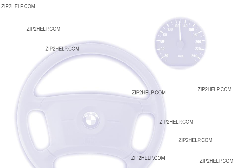
Instrument cluster
1 Fuel gauge 80
2Indicator lamp for turn signals 20
3Speedometer
4Indicator and warning lamps 18 to 21
5Tachometer and Energy Control 79, 79
6Engine coolant temperature gauge 80
7Indicator and warning lamps 18 to 21
8Control button for
>Time 82
>Service interval display 81
>Outside temperature display 83
9Selector lever and program display for automatic transmission/sequen- tial manual gearbox 19, 67, 73
10Display for
>Trip odometer/Odometer 79
>Clock 82
>Service interval 81
>Computer 82
11Check Control 81
12Trip odometer, reset to zero 79
13Indicator and warning lamps 18 to 21
17
 Repairs Maintenance Controls Overview
Index Data

18 Indicator and warning lamps
Technology that monitors itself
Indicator and warning lamps that are identified by ??? are tested for proper functioning whenever the ignition key is turned. They each light up once for dif- ferent periods of time.
If a fault should occur in one of these systems, the corresponding lamp does not go out after the engine is started, or it lights up while the vehicle is moving. You will see how to react to this in the following section.
Red: stop immediately
Battery charge current ???
The battery is no longer being charged. Indicates a defective alternator drive belt or a problem with the alternator's charge circuit. Please
contact the nearest BMW center.
If the drive belt is defective, stop and switch off the engine immedi-
ately to prevent overheating and seri- ous engine damage. If the drive belt is defective, increased steering effort is also required.<
Engine oil pressure ???
Stop the vehicle immediately and switch off the engine.
Check the engine oil level and top off as required. If the oil level is correct: please contact the nearest BMW cen- ter.
Do not continue driving, as the engine could sustain serious dam-
age from inadequate lubrication.<
Brake warning lamp ???
If the lamp comes on when the parking brake is not engaged: check the brake fluid level. Before driv-
ing further, be sure to comply with the instructions on pages 122 and 135.
Brake warning lamp for Cana- dian models.
Flat Tire Monitor ???
In addition, an acoustic signal is sounded: there is a flat tire.
Reduce speed and carefully come to a stop. Avoid sudden braking and steer- ing maneuvers.
For additional information: refer to page 91
Red and yellow: continue driving cautiously
The brake warning lamp comes on together with the yellow indi- cator lamps for ABS ??? and DSC:
The entire ABS, CBC, DSC and
full brake applications. Please have the system checked by your BMW center as soon as possible.
Additional information beginning on page 86
CBC, ABS, DSC and
Red: an important reminder
Brake warning lamp ??? Comes on when the parking
brake is engaged ??? an additional acoustic signal sounds when starting off. For additional information: refer to page 65

Brake warning lamp for Cana- dian models.
Please fasten safety belts ??? Comes on together with an acoustic signal until the safety
belts are fastened.
For additional information on safety belts: refer to page 48
Airbags ???
Please have the system inspected at your BMW center.
For additional information: refer to page 54
Orange: consult the nearest BMW center
Automatic tranmission/sequen- tial manual gearbox
The respective transmission has responded to a malfunction by reverting to operation in its emergency default program. Please consult the nearest BMW center.
For additional information: refer to pages 67, 71
Yellow: check as soon as possible
Engine oil level
If the lamp comes on during normal vehicle operation: the
engine oil level has fallen to the abso- lute minimum; refill as soon as possible. Do not drive more than approx.
30 miles/50 km before refilling. For additional information: refer to page 132
Engine oil level
Comes on after the engine has been switched off: add engine
oil at the earliest opportunity ??? next time you stop to refuel.
For additional information: refer to page 132
Brake pads ???
Have the brake pads checked. For additional information: refer
to page 122
Flat Tire Monitor ???
The Flat Tire Monitor is malfunc- tioning or out of order. Please
have the system inspected at your BMW center.
For additional information: refer to page 91
Dynamic Stability Control (DSC) ???
Indicator lamp flashes:
The system is actively regulating drive torque and braking force.
The indicator lamp stays lit:
DSC has been switched off with the button; DTC is operational.
Please contact the nearest BMW center in case of a malfunction.
Additional information beginning on page 86
325xi:
DSC has been switched off manually or there is a system malfunction.
Please consult the nearest BMW cen- ter.
For additional information: refer to page 88
Repairs Maintenance Controls Overview
Index Data

20 Indicator and warning lamps
Dynamic Stability Control (DSC) and brake warning lamp ???
The indicator lamps remain on: DSC/DTC have been switched off with the button or are faulty. Please consult the nearest BMW
center.
Additional information beginning on page 86
325xi:
DSC and
Please consult the nearest BMW cen- ter.
DSC indicator and brake warn- ing lamps for Canadian models.
Dynamic Brake Control (DBC) ??? Malfunction in DBC system. Conventional braking efficiency
is available and unrestricted.
Have the system repaired at your BMW center as soon as possible.
Additional information beginning on page 121
Dynamic Brake Control (DBC) warning lamp for Canadian models.
Add washer fluid
The washer fluid level is too low. Top off the fluid at the earliest
opportunity.
For additional information: refer to page 132
CHECK GAS CAP* ???
This indicator lamp comes on when the gas cap is loose or
missing.
Close the gas cap tightly: refer to page 24
SERVICE ENGINE SOON ???
If the indicator lamp comes on either continuously or intermit-
tently, this indicates a fault in the emis-
For additional information: refer to page 138
Service Engine Soon indicator lamp for Canadian models.
Engine electronics ???
There is a fault in the electronic
You can continue to drive with reduced engine output or engine speed. Please have the system inspected at your BMW center.
Add coolant
The coolant level is too low. Add coolant at the earliest opportu-
nity.
For additional information: refer to page 134
Green: for your information
Turn signal indicator
Flashes when the turn signals are on.
Rapid flashing indicates a system mal- function.
For additional information: refer to page 74
Cruise control
Lights up when the cruise con- trol is activated: ready for oper-
ation via the buttons in the steering wheel.
For additional information: refer to page 77
Indicator and warning lamps
Front fog lamps
Lights up whenever you switch on the fog lamps.
For additional information: refer to page 95
Blue: for your information
High beams
Comes on when the high beams are on or the headlamp flasher
is actuated.
For additional information: refer to pages 74, 94
21
 Repairs Maintenance Controls Overview
Index Data

22 Buttons in steering wheel*
These buttons let you operate the fol- lowing functions quickly and without being distracted from traffic conditions:
>Selected radio functions
>The cruise control
>Selected telephone functions
>The voice recognition system.
The controls are active only when the corresponding systems and
accessories are switched on.<
Press briefly:
Receive a phone call, initiate dialing, terminate a call.
Extended pressure:
Switch voice recognition on and off.
Switch between phone, radio, cassette and CD.
Forward:
>Radio
Press briefly: next station in station memory
Extended pressure: station search
>CD
Press briefly: jump to next track
Extended pressure: search function in track
>Cassette
Press briefly: jump to next track or stop fast forward
Extended pressure: fast forward
>Phone
Scan personal phone book.
Rewind/reverse: same functions as for- ward.
Volume.
Cruise control: store and accelerate + or decelerate and store
Cruise control: activate/interrupt/deac- tivate.
Cruise control: select a stored setting.
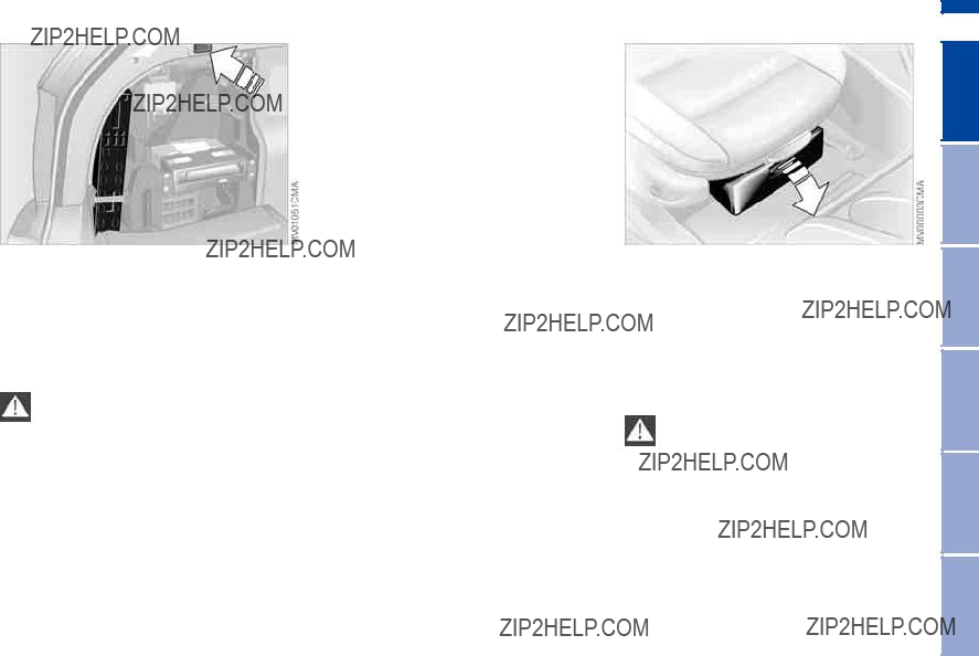
Hazard warning triangle*
The warning triangle is located on the left side of the cargo area behind the cover panel.
To open: press the button and remove the cover.
Always observe all legal regula- tions requiring a warning triangle
to be carried in the vehicle.<
The
To open: pull the handle and fold the cover down.
To close: fold the cover up and press it until the tab engages.
Some of the articles in the
before expiration. For this reason, check the expiration dates of each of the items regularly and replace any whose expiration dates have passed. You can purchase replacements in any drugstore or pharmacy.
Always observe all legal regulations requiring a
 Repairs Maintenance Controls Overview
Index Data

24 Refueling
Always observe all safety precau- tions posted at the service station
when handling fuel. Never carry spare fuel containers in your vehicle. Whether empty or full, these containers can leak, cause an explosion, or lead to fire in the event of a collision.<
Fuel filler door
Always switch off the engine before refueling, as it is not possi-
ble to add fuel with the engine running, and attempts may also trigger the SERVICE ENGINE SOON lamp.<
Press on the rear edge of the fuel filler door to open and close it.
If an electrical malfunction occurs, you can unlock the fuel filler door manually:
1.Release the side trim on the right- hand sidewall of the cargo area
2.Pull the knob with the fuel pump symbol.
Simple and environmentally friendly
Open the gas cap carefully to pre- vent fuel from spraying out. Fuel
spray may cause injury.<
Keep the gas cap in the bracket attached to the fuel filler door.
When refueling, insert the filler nozzle completely into the filler pipe. Lifting the nozzle during refueling
>results in premature pump shutoff
>and will reduce the effectiveness of the vapor recovery system on the pump.
The fuel tank is full when the filler noz- zle shuts off the first time.
Refueling
Close the gas cap carefully after refueling until a click is heard.
While closing, be sure not to squeeze the strap which is fastened to the cap. A loose or missing cap will activate the CHECK GAS CAP* lamp.<
Fuel tank capacity
>Approx. 16.6 gal./63 liters, of which
>approx. 2.1 gal./8 liters are reserve capacity.
Do not drive to the last drop of fuel. This can prevent the engine
from operating properly and result in damage.<
The engine uses
Required fuel:
>Premium Unleaded Gasoline, min. 91 AKI.
AKI = Anti Knock Index
Never use leaded fuel, as it would cause permanent and irreversible
damage to the oxygen sensor and the catalytic converter.<
Checking tire pressures
Tire pressures in psi/kilopascal are shown on the driver's door post and are visible when the door is open.
Only check the tire inflation pressures of cold tires. This means after driving a maximum of 1.25 miles/2 km or after the vehicle has been parked for at least 2 hours. Warm tires have higher infla- tion pressures.
In the following tire inflation pressure table, all pressures are specified in the standard units of pressure, psi and kilo- pascal, and apply to cold tires, i.e. tires at ambient temperature.
 Repairs Maintenance Controls Overview
Index Data

26 Tire inflation pressure
Vehicles with Flat Tire Monitor:
After correcting the inflation pressures, reinitialize the system. Refer to
page 91.
Check the tire pressures on a reg- ular basis ??? at least twice a month
??? and before every extended journey. If this is not done, incorrect tire pressures can cause driving instability and tire damage, ultimately resulting in acci- dents.
Remember to check the inflation pres- sure in the
Inflate the spare tire to the highest infla- tion pressure specified for your vehi- cle.<
Comply with tire approval specifications
The inflation pressures in the table apply to BMW approved tire sizes and tire manufacturers. Your BMW center can provide you with more information about these. Other pressures may be required for tires made by other manu- facturers.
Your vehicle is equipped with tires that not only meet US standards, but also European standards. We recommend the exclusive use of BMW approved tires.

Tire inflation pressure
27
 Repairs Maintenance Controls Overview
Index Data

28

29
Overview
Controls and features
Operation, maintenance
Owner service procedures
Technical data
Index
 Repairs Maintenance Controls Overview
Index Data

2 Spare key ??? for storage in a safe place, such as in your wallet. This key is not intended for constant use. The glove compartment cannot be locked and unlocked with this key ??? which is useful for valet parking, for example
The key set
1Master keys with remote control unit
??? these keys determine the functions of the Key Memory. Refer to page 61. You can mark the individual keys for subsequent identification by apply- ing the colored decals that you received when accepting delivery of your vehicle
In every master key there is an
charged automatically in the ignition lock as you drive.
For this reason, if you have master keys that are not being used, you should use those keys at least once a year while driving for an extended period to charge the battery, refer also to
page 31.<
The concept
The central locking system is ready for operation whenever the driver's door is closed. The system simultaneously engages and releases the locks on the
>doors
>tailgate and rear window
>fuel filler door.
The central locking system can be operated
>from outside via the remote control as well as via the driver's door lock
>from inside by pressing a button.
The fuel filler door is not locked when the central locking system is activated from the inside, refer to page 35. When the system is actuated from the out- side, the
If locked from the inside, the central locking system unlocks automatically in the event of an accident, except on doors that have been locked individu- ally using the lock buttons, refer to page 35. In addition, the hazard warn- ing flashers and interior lamps come on.
The concept
The remote control also provides two additional functions beyond the central locking feature:
>To switch on interior lamps, refer to page 32.
With this function you can also search for the vehicle when parked in an underground garage, for instance
>Opening the rear window, refer to page 32.
The rear window will open slightly, regardless of whether it was previ- ously locked or unlocked.
Whenever you unlock or lock the vehi- cle, you simultaneously deactivate/acti- vate the
You can have a signal set to con- firm that the vehicle's locks have
engaged securely.<
Master keys with remote control
Persons or animals inside the vehicle may be able to lock the
doors from the inside. For this reason, always take the vehicle keys with you so that the vehicle can be opened again from the outside at any time.<
If it is no longer possible to lock the vehicle via the remote control,
the battery is discharged. Use this key while driving for an extended period in order to recharge the battery. To pre- vent unauthorized use of the remote control, surrender only the spare key when leaving the vehicle for valet park- ing, for example.
In the event of a system malfunction, please contact your BMW center. You can also obtain replacement keys there.<
1Unlock, convenience opening mode, and disarm alarm system
2Lock and secure, arm alarm system, activate interior lamps, disarm tilt alarm sensor and interior motion sen- sor
3Open the rear window, Panic mode ??? trigger alarm
To release
Press the button once to unlock the driver's door.
Press the button a second time to unlock all vehicle locks.
 Repairs Maintenance Controls Overview
Index Data

32 Opening and closing ??? via the remote control
Convenience opening mode
Press and hold button: to open the electric power windows and glass sun- roof.
To lock and secure
Press button.
To switch on the interior lamps
After locking the vehicle, press button again.
To deactivate the tilt alarm* and interior motion sensors*
Press button a second time immedi- ately after locking.
For additional information, refer to page 39.
To open the rear window
Press button.
the rear window opens slightly. It can now be tilted up.
If the vehicle is locked, the rear window will be locked again after
it is closed.
Before and after a trip, be sure that the rear window has not been opened unin- tentionally.<
If you prefer, the tailgate will open instead of the rear window.<
Panic mode ??? trigger alarm
By pressing the button for more than 2 seconds, the alarm system can be triggered in the event of danger, if it is armed.
To switch of the alarm:
Press button.
External systems
The remote control system's operation may be affected by other units or equipment operating in the immediate vicinity of your vehicle.
If this should occur, you can still open and close the vehicle using the master key in the door lock.
For US owners only
The transmitter and receiver units com- ply with part 15 of the FCC/Federal Communications Commission regula- tions. Operation is governed by the fol- lowing:
FCC ID:
>LX8EWS
>LX8FZVS
>LX8FZVE.
Compliance statement:
This device complies with part 15 of the FCC Rules. Operation is subject to the following two conditions:
>This device may not cause harmful interference, and
>this device must accept any interfer- ence received, including interference that may cause undesired operation.

Opening and closing ??? via the remote control
Any unauthorized modifications to these devices could void the
user's authority to operate the equip- ment.<
33
 Repairs Maintenance Controls Overview
Index Data

34 Opening and closing ??? via the door lock
Whenever closing the windows or sliding/tilt sunroof you should
always monitor their path and progress to ensure that no one is injured. Releas- ing the key stops the operation.<
Manual operation
In the event of electrical malfunction
Turn the key all the way to the left or right to unlock or lock the driver's door.
One turn of the key in the driver's door lock unlocks the driver's door only. Turning the key a second time unlocks all of the remaining doors, the tailgate and the fuel filler door.
You can have a signal set to con- firm that the vehicle's locks have
engaged securely.<
Convenience operation
You can also operate the power win- dows and the glass sunroof via the door lock.
>To open: with the door closed, hold the key in the Unlock position
>To close: with the door closed, hold the key in the Lock position.

Opening and closing ??? from the inside
You can use this button to operate the central locking system when the front doors are closed. With this button, only the doors, the tailgate and rear window are unlocked or locked. The
If only the driver's door was unlocked from the outside and
you press the button, then, with the driver's door still open, the passenger- side door, the tailgate and the fuel filler door will unlock, too.
If the driver's door is closed, it will be locked.<
If you desire, the central locking system can be activated automati-
cally as soon as you begin to drive. This can be adjusted to be
To unlock and open the doors
1.Press the button for the central lock- ing system
2.Pull the release handle above the armrest on the door you wish to open
or
pull the release handle for any door twice: to unlock and open the door.
To lock
>Either use the central locking button to lock all doors at once or
>press the individual door lock buttons down. To prevent the driver from being inadvertently locked out of the vehicle, the driver's door lock button will not engage as long as the door is open.
Persons or animals inside the vehicle may be able to lock the
doors from the inside. For this reason, always take the vehicle's keys with you so that you can open the vehicle again from the outside at any time.<
To open from the outside
To avoid damage, check to ensure that you have adequate clearance
before opening the tailgate.<
Press the button in the handle recess: the tailgate opens slightly.
The cargo area is illuminated when the tailgate is open.
 Repairs Maintenance Controls Overview
Index Data

Manual operation
>Fold rear center armrest or rear back- rest forward
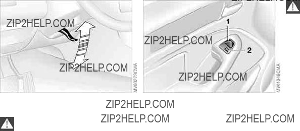
>Remove cover 1 ??? this operation is easy to carry out with the aid of the ignition key
>Press the lever ??? see arrow ??? to the right.
The tailgate is locked again as soon as you close the lid.
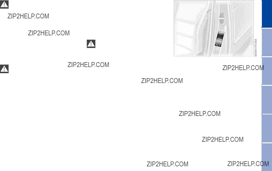
To open from the inside*
If the tailgate has not been locked sep- arately, you can open it with this button in the footwell on the driver's side when the vehicle is stationary.
To close
The handle recesses in the interior trim panel of the tailgate make it easier to pull the tailgate down.
Both before starting off and after completing every journey, check to ensure that neither the rear window
nor the tailgate has been opened inad- vertently.<
To avoid injuries, be sure that the travel path of the tailgate is clear
when it is closed, following the same precautions as with all closing proce- dures.<

Rear window
Always drive with both the tailgate and the rear window securely
closed, as exhaust gases might other- wise be drawn into the interior of the vehicle.<
Should it be absolutely necessary to operate the vehicle with the tailgate or the rear window open:
1.Close all windows and the glass sun- roof
2.Greatly increase the quantity of air coming from the air conditioning or automatic climate control system, refer to page 96 or 100.
To open from the outside
Small items can be loaded or unloaded quickly if the rear window is opened separately.
Press button ??? see arrow: the rear win- dow opens slightly. It can now be tilted up.
Opening with the remote control, refer to page 32.
Push the window down to close it.
If pointed or
driving, be sure to provide protection around all edges. If you do not do this, the heating conductors of the rear win- dow could be damaged.<
Luggage straps
Use the retaining straps on the cargo area floor to secure smaller items of luggage.
Movement is reduced when objects are placed on the straps.
To secure your luggage, use the lug- gage compartment nets* or flexible straps that you can attach to the fittings at the inner corners of the cargo area.
Refer also to Cargo loading on page 113.
For additional details in the cargo area and for the cargo area cover, please refer to Cargo area beginning on page 111.
 Repairs Maintenance Controls Overview
Index Data

38 Alarm system*
The concept
The vehicle alarm system responds:
>When a door, the hood, the tailgate or the rear window is opened
>To movement inside the vehicle ??? interior motion sensor
>To variations in the vehicle's tilt angle such as those occurring during attempts to steal the wheels or tow the vehicle
>To interruption of battery voltage.
The system responds to unauthorized vehicle entry and attempted theft by simultaneously activating the following:
>Sounding an acoustic alarm for 30 seconds
>The hazard warning flashers are acti- vated for approx. five minutes
>Flashing the high beams on and off in rhythm with the hazard warning flash- ers.
To arm and disarm the alarm system
When the vehicle is locked or unlocked via the driver's door lock or with the remote control, the alarm system is also simultaneously armed or disarmed.
You can have different acknowl- edgment signals set to confirm
arming and disarming.<
You can also open the rear window when the system is armed by pressing the remote control button, refer to page 32. The window is once again secured when it is closed.
Extended pressure on the button sets off the alarm ??? Panic mode, refer to page 32.
Indicator lamp displays
>The indicator lamp below the interior rearview mirror flashes continuously: The system is armed
>The indicator lamp flashes while the system is armed: a door, the hood, the tailgate or rear window is not completely closed. Even if you do not close the alerted area(s), the remain- ing areas are secured, and the indi- cator lamp will flash continuously after 10 seconds. However, the inte- rior motion sensor is not activated
>The indicator lamp goes out when the system is disarmed: no manipulation or attempted intrusions have been detected in the period since the sys- tem was armed
>The indicator lamp flashes for
10 seconds when the system is dis-
Alarm system*
39
armed: an attempted entry has been detected in the period since the sys- tem was armed.
Following triggering of an alarm, the indicator lamp will flash continuously.
Avoiding unintentional alarms
The tilt alarm sensor and interior motion sensor may be switched off at the same time. You can do this to prevent a false alarm from being triggered in garages with elevator ramps, for instance, or when the vehicle is transported by train:
Lock the vehicle twice to arm the sys- tem. Press the button on the remote control twice in succession or lock the vehicle twice with the key.
The indicator lamp lights up briefly and then flashes continuously. The tilt alarm sensor and the interior motion sensor are deactivated as long as the system is armed.
You can have the tilt alarm sensor and the interior motion sensor
permanently deactivated.<
Interior motion sensor
In order for the interior motion sensor to function properly, the windows and the glass sunroof must be completely closed.
Nevertheless, you should deactivate the interior motion sensor, refer to Avoiding unintentional alarms, if
>persons or animals are left in the vehicle
>the windows or the glass sunroof are being left open.
The system deactivates the tilt- alarm sensor and the interior
motion sensor if the convenience clos- ing of windows and the glass sunroof is interrupted in the first 10 seconds and then restarted. The alarm must then be disarmed and reactivated before it will resume operation.<
 Repairs Maintenance Controls Overview
Index Data

40 Electric power windows
To open and close windows
When leaving the vehicle, always remove the ignition key from the lock and remember to close the doors
to prevent persons or animals from operating the power windows and injur- ing themselves, etc.<
After the ignition has been switched off: You can still operate the electric power windows for up to 15 minutes, as long as no one opens either of the front doors.
With the ignition key in position 1 or higher
>Press the switch until you feel resis- tance: the window retracts as long as you maintain pressure on the switch
>Press the switch briefly past the pres- sure point: the windows move auto- matically. Pressing the switch again stops the opening cycle.
You can close the windows in the same manner by pulling the switch.
If your vehicle is equipped with optional electric power windows in the rear* separate switches will be located below the windows.
For convenience operation via the door lock, refer to page 34.
Safety feature
The front windows are each equipped with contact strips located in the upper window frames. If pressure is exerted against this contact strip while a win- dow is being raised, the system will respond by stopping the window and then retracting it a small distance.
Despite this safety feature, be extremely careful to ensure that
the closing path of the window is not obstructed. Some types of objects might fail to trigger the contact strip in some situations ??? very thin objects, for instance.
You can override this safety feature by pressing the switch beyond the resis- tance point and holding it.<
Electric power windows
Safety switch
With the safety switch, you can prevent the rear windows from being opened or closed via the switches in the rear pas- senger area, for example by children.
Press the safety switch whenever persons or animals are riding in
the rear of the vehicle. Careless use of the power windows can lead to injury.<
Glass sunroof, electric* 41 
42 Glass sunroof, electric*
Opening and closing
With the ignition key in position 1 or higher
>Slide the switch until you feel resis- tance: the sunroof opens and closes as long as you hold the switch
>Slide the switch briefly past the pres- sure point: the sunroof moves auto- matically.
Tapping the switch again stops the motion immediately.
The headliner insert retracts with the sunroof while it is opening.
After the ignition has been switched off: You can still operate the sunroof for up to 15 minutes, as long as no one opens either of the front doors.
For convenience operation via the door lock, refer to page 32 or 34.
Raising the glass sunroof
With the ignition key in position 1 or higher: tap the switch.
Tapping the switch again stops the motion immediately.
If you briefly press the switch in the raise direction while the sunroof is open, the sunroof will rise to its upper- most position.
After the ignition has been switched off: You can still operate the sunroof for up to 15 minutes, as long as no one opens either of the front doors.
The headliner insert slides back some- what when you raise the sunroof.
Do not use force to close the headliner insert with the sunroof in
its raised position, as damage to the mechanism could result.<
Safety feature
If the glass sunroof encounters resis- tance
>when it is closing from the raised position
>when it is closing from a point roughly past the middle of its travel,
the closing cycle is interrupted and the glass sunroof will open again slightly.
Despite this safety feature, be extremely careful that the travel
path of the sunroof is not obstructed whenever it is closed. Remember that the safety mechanism may not be able to detect obstructions under all circum- stances ??? with very thin objects, for instance.
You can disable this safety feature by pressing the switch beyond the pres- sure point and holding it.<

Glass sunroof, electric*
Manual operation
In the event of an electrical malfunction, you can also operate the glass sunroof manually
1.Remove the interior lamp, then reach into the exposed opening and press out the cover
2.Use the Allen key from the onboard tool kit, refer to page 142, to turn the glass sunroof in the desired direc- tion.
43
 Repairs Maintenance Controls Overview
Index Data

44 Safe seating position
For driving that is relaxed and less likely to cause fatigue, you should select a sitting position that reflects your per- sonal requirements. In combination with the safety belts and airbags, the correct seating position also plays an important role in enhancing occupant safety in the event of an accident. To ensure that the vehicle's safety systems provide you with optimal protection, we request that you direct your careful attention to the following section.
For additional information on transport- ing children refer to page 57.
Sitting safely with airbags
Always maintain an adequate dis- tance between yourself and the
airbags. Always hold the steering wheel by the rim to keep any chance of injury to hands or arms to an absolute mini- mum should the airbag be deployed. Never allow any objects, individuals or animals to obstruct the areas between passengers and airbags. Never use the front airbag's cover as a storage tray or support for objects of any kind. Never allow front passengers to rest their feet or legs on the airbag cover.<
For airbag locations and additional information on airbags, refer to page 54.
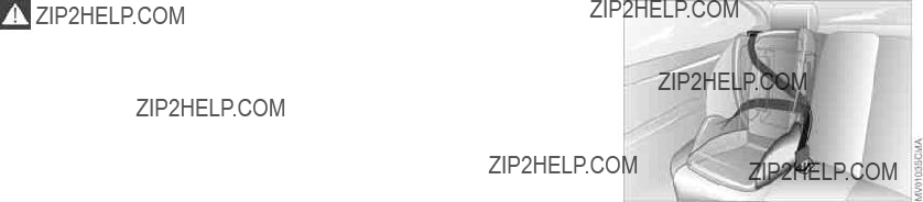
Sitting safely with safety belts
Your vehicle offers five sitting positions, each of which is provided with a safety belt.
Never allow more than one person to wear a single safety belt. Never allow infants or small children to ride in
a passenger's lap. Avoid twisting the belt while routing it firmly across the hips and shoulder, wear it as snugly against your body as possible. Do not allow the belt to rest against hard or fragile objects. Do not route the belt across your neck, or run it across sharp edges. Be sure that the belt does not become caught or jammed. Avoid wearing loose or bulky clothing. You should remember to retension the lap belt periodically by pulling the shoulder strap to take up any slack in the mecha- nism. In the event of a frontal impact, a loose lap belt could slide over your hips, leading to abdominal injury. In addition, the safety belt's restraint effectiveness is reduced if the belt is worn loosely. Expectant mothers should always wear their safety belts, taking care to position the lap belt against the lower hips, where it will not exert pressure against the abdominal area.<
For information on using the safety belts, refer to page 48.

When adjusting your seat, always observe the following precautions
Never try to adjust your seat while operating the vehicle. The seat
could respond with unexpected move- ment, and the ensuing loss of vehicle control could lead to an accident. Never ride with the backrest reclined to an extreme horizontal angle. This is espe- cially important for front passengers to remember. Keep the backrest relatively upright to minimize the risk of sliding under the safety belt and sustaining injury in an accident.<
Seat adjustment
>Manual seat adjustment, refer to page 45
>Power seat adjustment, refer to page 47
>Head restraint, refer to page 48.
Seat adjustment
1Backward/forward adjustment
Pull the lever and slide the seat to the desired position.
After you release the lever, move the seat forward or backward slightly so that it engages fully
2Cushion height
Pull the lever and apply weight to or remove weight from the seat as required
3Backrest angle
Pull the lever and apply weight to or remove weight from the backrest as required
 Repairs Maintenance Controls Overview
Index Data

46 Manual seat adjustment
BMW sport seat* adjustment
You can also adjust the tilt angle and the thigh support:
1To raise:
Pull the lever repeatedly, continuing until the seat is at the desired tilt angle
2To lower:
Push the lever repeatedly, continuing until the seat is at the desired tilt angle
3Thigh support:
Pull the lever and adjust the position of the thigh support for your personal comfort

Power seat adjustment*
Seat adjustment
1Tilt angle
2Backward/forward adjustment
3Cushion height
4Backrest angle
The head restraint is adjusted manually, refer to page 48.
The thigh support and the head restraint are adjusted manually, refer to pages 46, 48.
Please refer to the adjustment instructions on page 45 to reduce
the risk of personal injury.<
To adjust
You can adjust the backrest's contour for additional support in the curvature of your spine's lumbar region.
The upper hips and spinal column receive supplementary support to help you maintain a relaxed, upright posture.
>Press front/rear of switch: increase/decrease curvature
>Press the upper/lower end of the switch: increase the upper/lower cur- vature.
 Repairs Maintenance Controls Overview
Index Data

2. Press button ??? see arrow 1 ??? and remove the head restraint.
Installation ??? front
Slide the head restraint into its guides.
To adjust
To adjust height: pull the head restraint up or push it down.
Press button ??? see arrow 1 ??? to retract to the lowest position.<
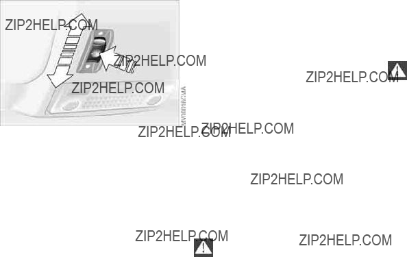
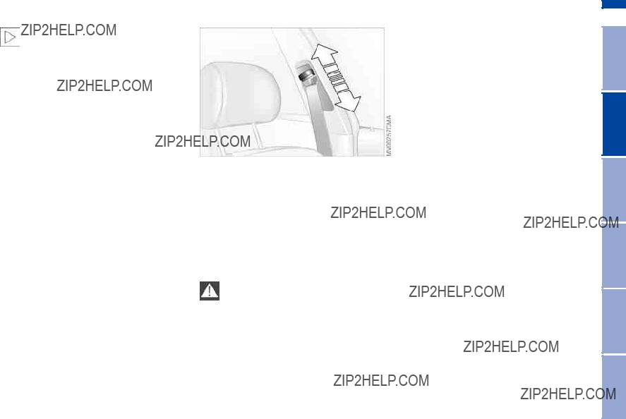
To adjust tilt angle of front head restraints: tilt them to the desired angle.
You can reduce the risk of spinal injury and whiplash by adjusting the head restraint to a height at which it
is centered roughly at ear level.<
Removal ??? front
Always wear your safety belt
Always fasten your safety belt before starting off. As supplemental restraint devices, the airbags are designed to enhance the effectiveness of the safety belts, and not to replace them.
To close
Make sure you hear the lock engage in the belt buckle.
To release
1.Press the red button in the buckle
2.Hold the belt
3.Guide belt into its inertia reel.
1.Pull the head restraint up to the end of its travel
Safety belts
The rear belt buckle with the word CENTER is intended exclusively
for the passenger sitting in the mid- dle.<
Adjusting safety belt height
Use the height adjustment mechanism to adapt the shoulder strap to the ideal level for your own body:
>Slide the button up or down.
Please refer to the seat adjustment instructions on page 44.
If the safety belt system has been subjected to the stresses involved
in an accident or otherwise damaged: have the entire safety belt mechanism replaced by your BMW center, includ- ing the safety belt tensioner. In addi- tion, have your BMW center inspect the safety belt anchors. If a
49
 Repairs Maintenance Controls Overview
Index Data
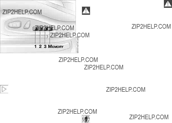
50 Seat and mirror memory*
You can store as many as three differ- ent driver's seat and mirror adjustment settings into the system for later selec- tion.
Memory will not retain the adjust- ment made to the lumbar sup-
port.<
To store
1.In ignition key position 1 or 2
2.Adjust the seat and door mirrors to the desired position
3.Press the MEMORY button: indica- tor lamp in the button comes on
4.Press memory button 1, 2 or 3, as desired: indicator lamp goes out.
To select a stored setting
Do not select a memory position while the vehicle is moving. If you
do so, there is a risk of accident from unexpected seat movement.<
Ignition key in position 1:
>Briefly press memory button 1, 2 or 3, as desired. Movement stops immedi- ately when one of the
The driver's door is closed and the igni- tion key is either removed or in position 0 or 2:
>Maintain pressure on the desired memory button ??? 1, 2 or 3 ??? until the adjustment process is completed.
If you press the MEMORY button acci- dentally: press the button again; the indicator lamp goes out.
Your BMW center can adjust your vehicle's systems in such a man- ner that your personalized settings are
automatically set for the seat and exte- rior mirror positions when you unlock the vehicle with your personal remote control.<
Before activating the programmed adjustment feature, ensure that
the footwell behind the driver's seat is empty and unobstructed. If you fail to do so, persons, animals or objects could be injured or damaged if the seat should move backward.<
Seat and mirror memory*
Automatic curb monitor*
1.Set the mirror selection switch 1 to the driver's door mirror position
2.When shifting into Reverse or placing the selector lever in position R, the
How far the passenger mirror tilts can be set individually for each
ignition key.<
You can deactivate this automatic fea- ture by setting the mirror selection switch to the passenger side position.
The seat cushion and backrest can be heated with the ignition key in position 2.
You can call up different heating modes by repeatedly pressing the button.
You can also switch the higher heating modes off directly:
Press the button and hold it slightly longer.
 Repairs Maintenance Controls Overview
Index Data
The mirror on the passenger's side features a lens with a more
convex surface than the mirror installed on the driver's side. When estimating the distance between yourself and other traffic, bear in mind that the objects reflected in the mirror are closer than they appear. This means that esti- mations of the distance to following traffic should not be regarded as pre- cise.<
To adjust
Never attempt to adjust the steer- ing wheel while driving the vehicle
??? it could respond with unexpected movement, posing a potential accident hazard.<
1.Fold down the detent lever
2.Adjust steering column reach and height for your selected seating posi- tion
3.Fold the detent lever back up to engage the lock.
To adjust exterior mirrors
1Switch for
2Selection switch for changing between mirrors
To adjust manually
You can also adjust the mirrors manu- ally:
Press against the edges of the lens.
For storing mirror settings, refer to Seat and mirror memory on page 50.
Electric defrosting*
Both mirrors are automatically heated when you turn the ignition key to position 2.

Mirrors
Interior rearview mirror
To reduce glare from vehicles behind you when you are driving at night, tilt the mirror by turning the knob.
Vehicles not equipped with an alarm system:
Fold the small lever forward.
Interior rearview mirror with automatic dimming feature*
This mirror automatically responds to ambient light and headlamp glare from following vehicles by dimming through an infinitely variable range and auto- matically reverts to its clear, undimmed setting whenever you shift into Reverse or move the selector lever into position R.
To ensure that the mirror continues to operate efficiently, ensure that the area adjacent to the photocells remains clean and unobstructed. One photocell is integrated within the mirror's lens ??? see arrow ??? while the other is located at an offset position on the rear of the mir-
53
ror. Refrain from attaching stickers or other objects to the windshield in the area immediately behind the rearview mirror.
 Repairs Maintenance Controls Overview
Index Data
54 Airbags
1Front airbags on the driver and pas- senger sides
2Head airbags for driver and front pas- senger
3Side airbags on the driver and pas- senger sides ??? front and rear*
Protective effect
The front airbags supplement the three- point safety belts by providing addi- tional protection in the event of a severe frontal collision in which the pro- tection afforded by the belts alone may no longer be sufficient. The head and side airbags help provide protection in the event of a collision from the side. The respective side airbag helps sup- port the seat occupant's upper body.
For information on the correct sitting posture, refer to page 44.
The side airbags in the rear pas- senger area* of your vehicle may
already have been deactivated by a BMW center. You may have them acti- vated if you desire to do so. Please contact your BMW center for additional information.<
The airbags do not deploy in response to minor collisions, rear
impacts and certain kinds of vehicle rollover.<
Do not apply adhesive materials to the cover panels of the airbags,
cover them or modify them in any other way. Do not remove the airbag restraint system. In the event of a malfunction, deactivation or triggered activation ??? as a response to an accident ??? of the air- bag restraint system, consult your BMW center for inspection, repair or disas- sembly. Do not modify or tamper with either the wiring or the individual com- ponents in the airbag system. These include the upholstered covers on the steering wheel, instrument panel, side trim panels of the doors and front roof pillars and on the sides of the headliner. Also, do not attempt to remove the steering wheel. Unprofessional attempts to service the system could lead to failure in an emergency or undesired airbag activation, either of which could result in personal injury. Do not touch the individual components immediately after the system has been activated, as this could result in per- sonal injury.<

Airbags
At all times, occupants should sit upright and be properly restrained
??? infants and small children in appropri- ate
Never let an occupant's head rest near or on a side airbag because the inflating airbag could cause a serious or fatal injury. Please note that the word Airbag imprinted on the door trim panel indi- cates the airbag's location.
Accident research shows that the saf- est place for children in an automobile is in the rear seat. However, a child sit- ting in the rear seat and not properly restrained may place his or her head on or near the airbag, if so equipped. For example, a child ??? even though belted in ??? may fall asleep with his or her head against the side airbag. It may be diffi- cult for a driver to ensure that children in the rear seat will remain properly positioned at all times and not place their heads on or near the side airbag. Therefore, we recommend that the rear seat side airbags, if installed in the vehicle, be deactivated if children will travel in the rear seat.
The rear seat side airbags may already have been deactivated by a BMW cen- ter. If you are uncertain of their status, or wish to have the airbags activated or
deactivated, please contact your BMW center.<
Even when all these guidelines are fol- lowed, there is still a small residual risk of injuries to the face, hands and arms occurring from airbag deployment in isolated instances.
In sensitive individuals, the ignition and inflation noise may induce a mild hear- ing loss that is temporary in most cases.
Corresponding airbag warning labels are found on both sun visors.

56 Airbags
This is the right way a larger child should sit wearing the seat belt when rear side airbags are provided.
Indicator lamp
The indicator lamp indicates the operational status of the airbag system with the ignition key in
position 1 or higher.
System operational:
>The indicator lamp comes on briefly when you turn the ignition key to position 1 or higher.
System malfunction:
>The indicator lamp does not come on or
>the indicator lamp lights up continu- ously.
If there is a system malfunction, there is a risk that the airbags will not be trig- gered within their normal response range, even if the level of impact would normally have triggered them.
Have your BMW center inspect the air- bag system immediately.

Transporting children safely
Commercially available
Correct location for installing
In your BMW, all seats equipped with a
If you use a
To gain access to this anchor fitting lift the plastic plug with the help of a screwdriver.
58 Transporting children safely
Before installing any child- restraint device or child seat,
please read the following:
Never install a
Your vehicle is equipped with an airbag supplemental restraint system for the front passenger. Because the backrest on any
that has first been properly secured with a safety belt.
Never install a
We strongly urge you to carefully read and comply with the instructions for installation and use provided by the
Be sure that all occupants ??? of all ages ??? remain properly and securely restrained at all times.<
All rear seating positions in your vehicle meet the recommendations of SAEJ1819, an
Securing
All of the rear belt retractors and the front passenger's safety belt can be locked for mounting and securing child- restraint systems.
A label with the appropriate instructions for this is located in the immediate vicinity of the buckle latch of each safety belt.
To lock the safety belt
Extract the entire length of the belt from the inertia reel mechanism. Allow the reel to retract the belt somewhat and engage the buckle, then tighten the belt against the
The belt cannot be extracted further. Always observe the installation instruc- tions provided by the manufacturer of the
To unlock the safety belt
Release the safety belt, remove the child seat and retract the safety belt to its end position on the belt retractor.
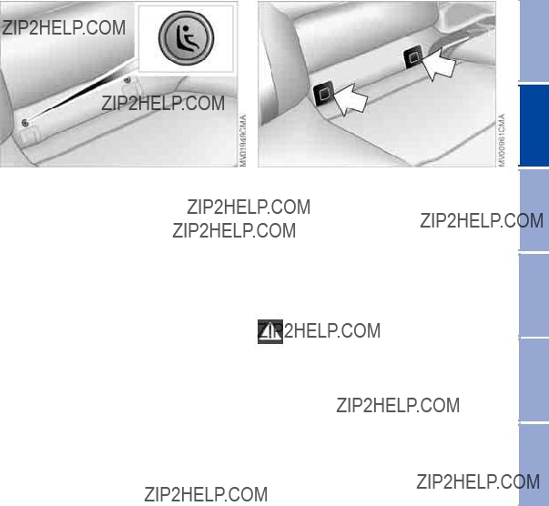
LATCH
LATCH: Lower Anchors and Tethers for CHildren
The left and right rear seats are both equipped with a LATCH
Canadian models only:
The LATCH anchorage points are iden- tified by buttons.
The illustration is an example showing the anchorages for a LATCH child seat system on the right rear seat.
The anchorages for the LATCH child seat system are concealed behind plas- tic covers that reclose when the LATCH child seat is removed.
Always follow all manufacturer's instructions and observe all safety
precautions when installing the LATCH
 Repairs Maintenance Controls Overview
Index Data

60 Transporting children safely
Child safety locks
Slide down the safety lever on the rear door:
The door can now be opened from the outside only.
Vehicle Memory, Key Memory
61
How the system functions
No doubt you have often reflected on how great it would be if you could per- manently configure your vehicle's vari- ous features and adjustments to mirror your own personal preferences. In engi- neering your vehicle, BMW has included a number of options for stor- ing personal adjustment data. These can be programmed at your BMW cen- ter.
The available configuration data fall into two categories, according to whether their primary orientation is the vehicle ??? Vehicle Memory ??? or the individual ??? Key Memory. Provided that each per- son has a separate
The system relies on a bilateral data exchange to identify the individual user and executes the selected settings whenever the remote control unit is used to disengage the locks.
Distinguishing between keys
What the system can do
You can learn about the entire array of features this system offers at your BMW center. Here are just a few examples:
You will see this symbol through- out the Owner's Manual. It is to
remind you at appropriate places of the settings that are available to you.<
Examples for Vehicle Memory:
>Various signals as acknowledgment when locking or unlocking your vehi- cle, refer to pages 31, 34
>Activates/deactivates the 'Follow me home' function, refer to page 93
>Activates/deactivates daytime driv- ing lamps, refer to page 93
>Sets the units of measure for display- ing time, outside temperature, dis- tance traveled and fuel consumption in the instrument cluster
>When you shift into Reverse, an acoustic signal indicates that PDC has been activated, refer to page 85
>Switches on rear window defroster automatically, to pages 98, 103
>Activates/deactivates various alarm system functions, refer to page 39
>After giving an ice warning, the onboard computer display returns to the previous setting, to page 83.
Examples for Key Memory:
>Locks the vehicle automatically after starting off, refer to page 35
>Unlocks the driver's door first, then the vehicle's remaining locks, refer to page 35
>Opens the tailgate instead of the rear window with the remote control, refer to page 32
>Automatically adjusts the driver's seat to the personal programmed settings when the vehicle is unlocked, refer to page 50
 Repairs Maintenance Controls Overview
Index Data
62Vehicle Memory, Key Memory
>Determines how far the passenger mirror will tilt, refer to Automatic curb monitor, page 51.

Ignition lock
Ignition key positions
0Steering locked
1Steering unlocked
2Ignition switched on
3Starting engine
Vehicles with automatic transmis- sion:
Do not move the selector lever from position P until the engine is running, ignition key position 2.
Your vehicle is equipped with an inter- lock. Therefore, the ignition key cannot be turned to position 0 or removed until the selector lever is in position P.<
Vehicles with manual transmis- sion:
Step on the clutch when starting the vehicle. A lockout prevents the engine from starting if the clutch is not depressed.<
Steering locked
The key can only be inserted and removed in this position.
After removing the key, turn the steer- ing wheel slightly to the left or right until the lock engages.
If the key is not removed, an acoustic signal is sounded after the driver's door has been opened.
Steering unlocked
You will find that it is often easier to turn the ignition key from position 0 to posi- tion 1 when you move the steering wheel slightly to help disengage the lock.
Individual electrical accessories are ready for operation.
Do not allow the engine to warm up by leaving it running while the
vehicle remains stationary. Instead, drive off immediately at a moderate engine speed.<
Do not allow the engine to run in enclosed spaces. Otherwise,
breathing the exhaust fumes can lead to unconsciousness and death. The exhaust gases contain carbon monox- ide, an odorless and colorless, but highly toxic gas. Do not leave the vehi- cle unattended with the engine running. An unattended vehicle with a running engine represents a safety hazard. When driving, standing at idle or park- ing the vehicle, take care to avoid con- tact between the hot exhaust system and flammable materials ??? grass, hay, leaves, etc. Such contact could lead to a fire, resulting in serious personal injury and property damage.<
Start the engine. Do not press the accelerator pedal.
Do not actuate the starter for too short a time, but do not actuate it
for more than approx. 20 seconds. Release the ignition key immediately when the engine starts.<
 Repairs Maintenance Controls Overview
Index Data

64 Starting the engine
If the engine does not start on the first attempt ??? if it is very hot or cold, for instance:
>Press the accelerator pedal halfway down while engaging the starter.
Cold start at very low temperatures of under approx.
>On the first start attempt, it may be necessary to engage the starter for a longer period, but no longer than
20 seconds
>Press the accelerator pedal halfway down while engaging the starter.
Extended starting attempts, char- acterized by excessively frequent
or long periods with the starter engaged, can damage the catalytic converter.<
Engine idle speed is controlled by the engine computer system. Increased speeds at
To prevent the battery from discharg- ing, always deactivate electrical devices that are not in use. Switch the ignition off when the vehicle is not being driven.
Manual transmission
1.Engage the parking brake
2.Gearshift lever in idling position
3.Start the engine.
Automatic transmission
1.Depress footbrake
2.Place the selector lever in position P or N
3.Start the engine.
To prevent the vehicle from start- ing off on its own, always move
the selector lever to position P and engage the parking brake before leav- ing your vehicle with the engine run- ning.
Do not leave the vehicle unattended with the engine running. An unattended vehicle with a running engine repre- sents a safety hazard.<
Sequential manual gearbox SMG
2.Place the selector lever in neutral position N
3.Start the engine.
If the engine does not start, reen- gage the gear last selected, refer to the gear indicator in the display, and
move the selector lever into neutral position N again.
The gearbox is automatically taken out of gear if the driver's door is opened while the engine is running and the driver does not actuate the pedals, the shift paddles or the selector lever. This is accompanied by a warning tone and the flashing gear indicator. The gear display N appears in the instrument cluster.<
Before exiting the vehicle with the engine running, move the selector lever into position N and apply the park-
ing brake.
Do not leave the vehicle unattended with the engine running. An unattended vehicle with a running engine repre- sents a safety hazard.<
1. Depress footbrake
Switching off the engine
You should never remove the igni- tion key when the vehicle is in
motion, as the steering lock could engage.
When you leave the vehicle, always remove the ignition key and engage the steering lock.
Always engage the parking brake when parking on downhill roads. Engaging a gear may not sufficiently secure the vehicle against rolling.<
Manual transmission
Turn the ignition key to position 1 or 0.
Automatic transmission
Move the selector lever into position P, and turn the ignition key to position 1 or 0.
SMG gearbox
If you turn the ignition key to position 1 or 0 with the selector lever in position R, or in sequential mode, a gear auto- matically remains engaged.
If you turn the ignition key to position 1 or 0 with the selector lever in neutral position N, a warning tone and the flashing gear indicator in the display remind you that no gear is engaged to secure the vehicle against rolling.
The warning stops after approx. 9 seconds.
If exceptional circumstances make it necessary to engage the
parking brake while the vehicle is in motion, do not pull it with excessive pressure. Keep your thumb pressed against the release button while care- fully pulling the lever up.
Excessive pressure can lead to over- braking and loss of traction ??? fishtailing
??? at the rear axle.
The brake lamps do not come on when the parking brake is engaged. Vehicles with manual or SMG gearbox: Engage the parking brake when parking on downhill roads, since engaging a gear may not provide adequate resis- tance to rolling, not even in first or reverse gear.
Vehicles with automatic transmission: place the selector lever in P.<
To avoid corrosion and
lightly from time to time when coasting to a standstill ??? at a traffic signal, for example ??? provided that it is safe to do so.<
Do not hold the vehicle in place on slopes by slipping or 'riding' the
clutch. Use the parking brake instead. Riding the clutch leads to severe and premature clutch wear.<
When changing gear in the 5th/6th gear plane, be sure to press the gearshift lever to the right to prevent inadvert- ently shifting to a gear of the 3rd/4th gear plane.
Reverse
Select only when the vehicle is station- ary. Press the shift lever to the left to overcome the resistance.
As you do this, the backup lamps will light up automatically when the ignition key is in position 2.

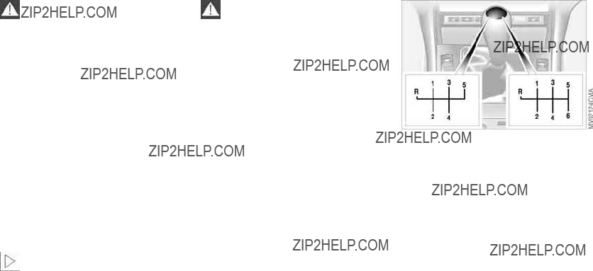
Sequential manual gearbox SMG*
The concept
The sequential manual gearbox SMG is an automated manual gearbox with which clutching and shifting is assumed by an
The SMG is operated via the selector lever in the center console and two shift paddles on the steering wheel.
It offers the following functions:
>Sequential mode: manual mode
>Drive mode: automatic operation
>Ability to choose between two differ- ent driving programs: Standard, Sport
>Operating safety through protection against misshifting
>Automatic upshifts and downshifts in the drive mode
>Automatic downshifts at minimum engine rpm
>Kickdown function in the drive mode.
>Acceleration assistant, refer to page 70.
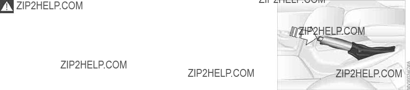
Selector lever positions
The current selector lever position is indicated by a
R: Reverse
N: Neutral
Position for forward driving with one- touch functions:
Sequential mode
+: manual upshifts
D: drive mode.
The SMG is ready for operation in igni- tion key position 2.

68 Sequential manual gearbox SMG*
R Reverse
Select only when the vehicle is station- ary.
To switch back to sequential mode: tap the selector lever again to the right toward D or change the current gear via the shift paddles or the selector lever.
N Neutral
Always engage before starting the engine, refer to Starting the engine on page 64.
Sequential mode
Each time the engine is started, the sequential mode is activated as soon as you move the selector lever into the for- ward driving position while the brake is depressed.
The gears are shifted via the shift pad- dles or the selector lever.
It is also possible to drive off in second gear, e.g. on
D Drive mode
In the drive mode all forward gears are shifted automatically.
To switch from sequential to drive mode: tap the selector lever to the right toward D.
For rapid acceleration, e.g. during passing, depress the accelerator pedal completely: kickdown.
Kickdown
You can achieve maximum acceleration using kickdown.
Depress the accelerator pedal past the increased resistance point at the full- throttle position.
Shifting gears
With selector lever:
>To upshift, tap the selector lever toward +
>To downshift, tap the lever toward
With shift paddles on steering wheel:
>To upshift, pull one of the shift pad- dles
>To downshift, push the paddle.
You accelerate from higher gears, e.g. during passing, by manually downshift- ing.
In the following situations, the SMG in the sequential mode assists you:
>The transmission will only execute upshifts and downshifts that will result in an appropriate combination of vehicle speed and engine rpm. For

Sequential manual gearbox SMG*
instance, downshifts that would result in excessive engine speed can- not be executed
>When you brake the car to a stop, the transmission automatically shifts down to first gear
>As speed diminishes, the transmis- sion will shift down automatically, without any action on your part, just before the vehicle slows to below each gear's minimum speed.
Available displays
R N 1 2 3 4 5 6
D1 D2 D3 D4 D5 D6
The currently engaged gear, the selected mode, and any malfunctions are displayed in the instrument cluster.
Indicator lamp
If the indicator lamp comes on, there is a malfunction in the transmission system.
All selector lever positions can still be engaged, but in the forward driving positions only certain gears are actually available when the vehicle is driven.
Avoid extreme loads and proceed to the nearest BMW center.
69
For information on
Warning tone
An acoustic signal sounds if the SMG gearbox overheats; if possible you should either stop or increase your pull- away speed so that the system can cool down.
 Repairs Maintenance Controls Overview
Index Data

70Sequential manual gearbox SMG*
1.Activate the Sport program
2.Press and hold the DSC button, refer to page 86, for more than three sec- onds
3.Quickly press the accelerator pedal down fully: kickdown. The optimum rpm for driving off will be adjusted.
To maintain vehicle stability, always drive with the DSC acti-
vated whenever possible.<
Sport program
You can choose between two driving programs: smoothly dynamic or Sport. With the Sport program, gearshifts are faster in sequential mode and the shift points are adapted in drive mode.
To activate the Sport program: press the SPORT button. The LED in the but- ton lights up.
Acceleration assistant
The acceleration assistant permits opti- mum
Do not use the acceleration assis- tant frequently as this could other- wise cause premature wear of the com-
ponents.<
Automatic transmission with Steptronic*
71
You can drive as with a normal auto- matic transmission. In addition, you can also shift manually.
When you move the selector lever from the D position to the left into the M/S range, the
Selector lever positions
P R N D M/S + ???
Starting the engine
The engine can only be started in selec- tor lever positions P ??? for Park ??? or N ??? for Neutral.
While the vehicle is stationary and before shifting out of Park or Neu-
tral, depress the footbrake in order to disengage the selector lever's lock mechanism ??? Shiftlock.<
Hold the footbrake down until starting off. The vehicle will other-
wise 'creep' when a drive position is engaged. To prevent the vehicle from starting off on its own, always move the selector lever to position P and engage the parking brake before leaving your vehicle with the engine running.
Do not leave the vehicle unattended with the engine running. An unattended vehicle with a running engine repre- sents a safety hazard.<
P Park
 Repairs Maintenance Controls Overview
Range selection
A catch prevents inadvertent movement of the selector lever to positions R and P. To deactivate the catch, press the button on the front of the selector lever knob, see arrow.
Select only when the vehicle is station- ary. Transmission locks to prevent rear wheels from turning.
R Reverse
Select only when the vehicle is station- ary.
Data
N Neutral
Select only when stopping for an extended period.
Index

72 Automatic transmission with Steptronic*
D Drive ??? automatic shift program
This position is designed for driving under all normal operating conditions. All forward gears are available.
Kickdown
In the kickdown mode, you achieve maximum acceleration and top speed in position D.
Depress the accelerator pedal past the increased resistance point at the full- throttle position.
M/S manual operation and Sport program
Move the selector lever from D to M/S to activate the Sport program; SD appears in the display panel. The M/S mode is recommended for perfor-
Once in the M/S mode, you can tap the selector lever to switch the automatic transmission from the Sport program to its manual mode.
This mode allows you to execute upshifts manually by tapping the lever toward +, while downshifts are selected by tapping in the ??? direction. The dis- plays M1 through M5 appear in the dis- play panel to indicate your current gear selection.
The transmission will only execute upshifts and downshifts that will result in an appropriate combination of vehi- cle speed and engine rpm. For instance, downshifts that would result in excessive engine speed are not exe- cuted. The desired, then the actual gear, briefly appear in the instrument cluster.
To accelerate quickly in the man- ual mode for maneuvers such as
passing another vehicle, shift down manually or employ the kickdown mode.<
Shifting from M/S to the selector lever positions P, R and N is possible only by going through D.

Automatic transmission with Steptronic*
73
Available displays
P R N D SD M1 M2 M3 M4 M5
If the indicator lamp does not go out, you can place the selector lever in all positions. However, the vehicle will now only operate in 3rd and 4th gear.
If this happens, avoid extreme engine loads and consult the nearest autho- rized BMW center.
Never work in the engine com- partment when a drive gear ??? for-
ward or reverse ??? is engaged. If you do this, the vehicle could move.<
For towing or
Maintenance Controls Overview
Electronic transmission control module
If the indicator lamp comes on, there is a malfunction in the transmission system.
Bring the vehicle to a stop. Move the transmission selector lever to P. Set the parking brake and turn the engine off ??? ignition key to position 0.
Wait a few seconds, then start the engine.
If the indicator lamp goes out after a few seconds, normal transmission per- formance has been restored. You may continue to drive as usual.
Repairs
Index Data
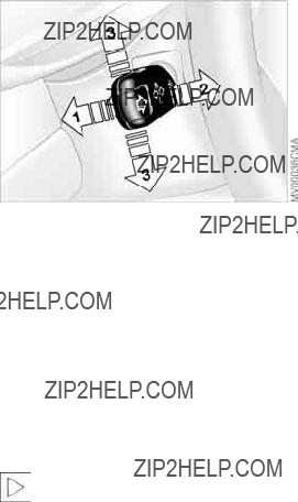
74 Turn signal indicator/Headlamp flasher
1High beams ??? blue indicator lamp
2Headlamp flasher ??? blue indicator lamp
3Turn signal indicator ??? green indicator lamps accompanied by a periodic clicking sound from the relay
To signal briefly
Press the lever up to but not beyond the resistance point. It then returns to the center position when released.
If the flashing indicator lamp and the clicking from the relay are
both faster than normal, one of the turn signal indicators has failed.<

0Wipers retracted
1Intermittent operation or rain sensor
2Normal wiper speed
3Fast wiper speed
4Brief wipe
5Rotary dial for control of the wipe interval or the sensitivity of the rain sensor
Intermittent mode
Not on vehicles with rain sensor.
You can set the wipe interval at four stages with rotary dial 5.
In addition, the wipe interval is varied automatically depending on road speed.
Rain sensor
The rain sensor is positioned on the windshield, directly behind the interior rearview mirror.
To activate the rain sensor:
>With the ignition key in position 1 or higher, move the lever to position 1. The wipers will make at least one sweep across the windshield.
You can leave the lever permanently in position 1. With the ignition key in position 1 or higher, all you then need to do to activate the rain sensor is
>briefly turn the rotary dial 5, or
>clean the windshield 1, refer to page 76.
To adjust the sensitivity of the rain sen- sor: turn rotary dial 5.
To deactivate the rain sensor: put lever in position 0.
Turn the rain sensor off in auto- matic car washes. Failure to do so
could result in damage caused by undesired wiper activation.<
Normal wiper speed
When the vehicle is stationary, the wip- ers switch automatically to intermittent wipe ??? not on vehicles with rain sensor.
Fast wiper speed
When the vehicle is stationary, the wip- ers revert to operation at normal speed
??? not on vehicles with rain sensor.
 Repairs Maintenance Controls Overview
Index Data

76 Washer/wiper system/Rain sensor*
The system sprays washer fluid against the windshield and activates the wipers for a brief period. When the vehicle's lighting system is switched on, the headlamps will also be cleaned at rea- sonable intervals.
Rear window wiper
Rear window wiper in intermittent mode. When reverse gear is engaged, continuous operation is switched on automatically.
Windshield washer nozzles
The windshield washer nozzles are heated automatically* when the ignition key is in position 2.
Cleaning windshield and headlamps*
0Wipers retracted
1Clean windshield and headlamps
2Rear window wiper intermittent mode
3Clean the rear window
Do not use the washers if there is any danger that the fluid will
freeze on the windshield, as your vision could be obscured. Always use a wind- shield washer antifreeze in cold weather. Refer to page 132.
Do not use the washers when the reser- voir is empty. This could cause damage to the washer pump.<
You can also program the interval:
>Briefly move the wiper lever from position 0 to position 2
>The period that elapses until the wip- ers again start to move ??? from position 0 to 2 ??? is the programmed interval for intermittent operation ??? max. 30 seconds.
Cleaning the rear window
The system sprays washer fluid onto the rear window.
To change the wiper blades refer to page 142.
Cruise control*
Starting at about 20 mph / 30 km/h, you can maintain and store any vehicle speed that you specify.
The cruise control is operational when- ever the engine is running and the sys- tem has been activated.
To activate the system
In ignition key position 2: press the but- ton in the steering wheel. The indicator lamp in the instrument cluster comes on, refer to page 20. You can now use the cruise control.
Do not use cruise control on twist- ing roads, when high traffic den-
sity prevents driving at a constant speed, or when the road surface is slick
??? snow, rain, ice ??? or loose ??? rocks or gravel, sand.<
To deactivate the system
Press button as often as you need to until the indicator lamp in the instru- ment cluster goes out.
Cruise control is also deactivated when the ignition key is in position 0.
The speed stored in memory is deleted.
To store and maintain speed or to accelerate
Press button + briefly:
The system stores and maintains the current vehicle speed. Every time you tap the button, the speed increases by approx. 0.6 mph / 1 km/h.
Press and hold button +:
The vehicle accelerates without pres- sure on the accelerator pedal. When you release the button, the system stores and maintains the current speed.
If on a downhill gradient the engine braking effect is not suffi-
cient, the controlled speed can be exceeded. Speed can drop on uphill grades if the engine output is insuffi- cient.<
To decelerate
Press button ??? briefly:
When cruise control is active, every tap of the button reduces the speed by approx. 0.6 mph / 1 km/h.
77
Press and hold button
With the cruise control active, the sys- tem automatically reduces the throttle opening to slow the vehicle. When you release the button, the system stores and maintains the current speed.
To interrupt the cruise control
When the system is activated, press the button. The indicator lamp stays on. You can use the cruise control again whenever you want by calling up the speed that was stored last.
In addition, cruise control is interrupted automatically:
>When the brakes are applied
>When you apply pressure to the clutch pedal, or when you move the automatic transmission selector lever from D to N
>If you exceed or fall below the preset speed for an extended period ??? by depressing the accelerator, for exam- ple.
 Repairs Maintenance Controls Overview
Index Data

78 Cruise control*
To recall the stored setting
Press button:
The vehicle accelerates to and main- tains the last speed stored.

Odometer
1Odometer
2Trip odometer
Odometer
You can activate the displays shown in the illustration with the ignition key in position 0 by pressing the left button in the instrument cluster.
Trip odometer
To reset the trip odometer to zero, press the left button with the ignition key in position 1 or higher.
Tachometer
Do not operate the engine with the nee- dle in the red overspeed zone of the gauge.
To protect the engine, the fuel supply is interrupted when you approach this sector.
Indicates the current fuel consumption in mpg ??? in liters/100 km on Canadian models. You can check your current driving style to see whether it is condu- cive to economy and minimum exhaust emissions.
When the vehicle is stationary, the dis- play goes to Maximum ??? zero on Cana- dian models.
 Repairs Maintenance Controls Overview
Index Data

Once the indicator lamp stays on con- tinuously, there are still approx.
2 gallons/8 liters of fuel in the fuel tank.
Fuel tank capacity approx. 16.6 gallons/63 liters
Certain operating conditions, such as those encountered in mountainous areas, may cause the needle to fluctu- ate slightly.
Fill the fuel tank before it is com- pletely empty. Driving to the last
drop of fuel can prevent the engine from operating properly and result in damage.<
When you switch on the ignition, the indicator lamp lights up briefly as an operation check.
To check coolant level, refer to page 134.
Blue
The engine is still cold. Drive at moder- ate engine and vehicle speeds.
Between the blue and red zones
Normal operating temperature. The needle may rise as far as the edge of the red sector in normal operation.
Red
When you switch on the ignition, the warning lamp comes on briefly to con- firm that the system is operational.
If the lamp comes on during normal vehicle operation: the engine has over- heated. Switch off the engine immedi- ately and allow it to cool down.
Service interval display
Remaining distance to service
The displays shown in the illustration appear for a few seconds when the ignition key is in position 1 or higher or after the engine is started.
The next service due appears with the message OIL SERVICE or INSPECTION, together with the dis- tance remaining in miles ??? in kilometers in Canada ??? before the next scheduled service.
The computer bases its calculations of the remaining distance on the preced- ing driving style.
A flashing message and a
When the ignition key is in position 2, the following information and/or condi- tions are indicated using symbols until the conditions have been corrected.
1Check the low beams and high beams, as well as the parking lamps
2Door open
3Tailgate open
4Check brake and tail lamps
When you open the driver's door, after having turned the ignition key to posi- tion 0, you will hear an acoustic signal for a few seconds to remind you that the lamps have not been switched off.
 Repairs Maintenance Controls Overview
Index Data

82 Clock
If you wish to have a permanent time display, you can make this setting in the radio display, refer to the Owner's Man- ual for Radio.
You can set the clock and the time dis- play in the car radio as follows.
Every time you press the button, the clock display alternates between the
In ignition key position 0: the time is displayed for a few seconds after you press the left button, refer to Odometer on page 79.
Setting
Before the clock can be set, the time must be showing in the
instrument cluster display.<
With the ignition key in position 1 or higher
To set ahead: turn the right button to the right.
To set back: turn the right button to the left.
The adjustment speed will increase the longer you continue to hold the right button.
To change the display mode: press the right button briefly.
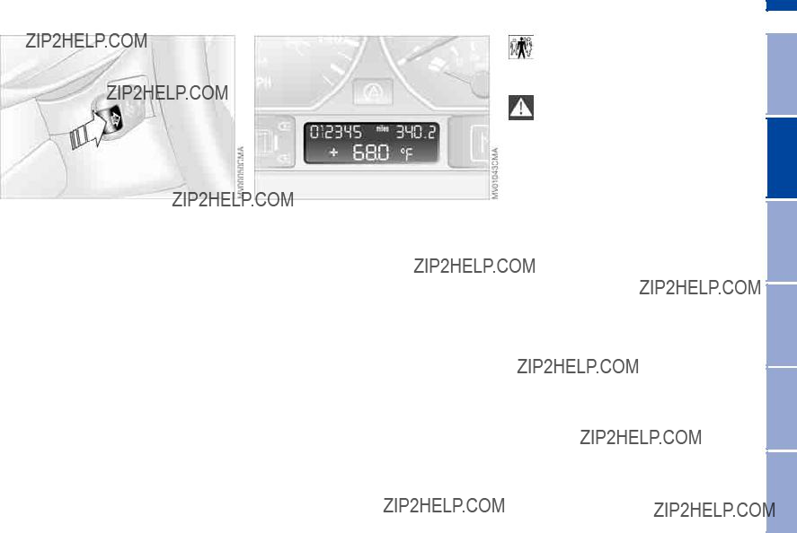
Computer*
Mode selection
With the ignition key in position 1 or higher, you can call up information from the computer using the button in the turn signal lever. By pressing the button briefly toward the steering column, you can call up a new function for display.
The displays appear in the following order:
Time of day, outside temperature, aver- age fuel consumption, cruising range, average vehicle speed.
With the ignition key in position 1 or higher, the last active setting is dis- played.
Outside temperature
You can change the units of measure 6/7 for the outside temperature dis- play by pressing the
Ice warning
If the outside temperature drops to about 37.57/+36, then the computer will automatically switch to a display of the outside temperature. In addition, a signal sounds as a warning and the dis- play flashes for a brief period.
83
After giving an ice warning, the display returns to the previous
setting.<
The ice warning does not alter the fact that surface ice can form at
temperatures above 37.57/+36, on bridges or shaded road surfaces, for instance.<
 Repairs Maintenance Controls Overview
Index Data

84 Computer*
Average fuel consumption
If you continue to hold the button on the turn signal lever, the average fuel con- sumption last displayed is recalculated from that point in time.
If you wish, you can have the aver- age fuel consumption displayed in
a different unit of measure.<
Range
The computer bases its calculations for the cruising range on operating condi- tions in the preceding period and on the remaining fuel in the tank.
It is important that you refuel when the cruising range falls below
approx. 35 miles/50 kilometers. Other- wise, the engine cannot be guaranteed to operate properly and damage may result.<
Average speed
If you continue to hold the button on the turn signal lever, the average speed being displayed is recalculated from that point in time.
Any time spent when the vehicle is sta- tionary and the engine is switched off is ignored for the calculation.

Park Distance Control (PDC)*
85
PDC does not remove the driver's personal responsibility for evaluat-
ing the distance between the vehicle and any objects. Even when sensors are involved, there is a blind spot in which objects cannot be detected. This applies especially in those cases where the system approaches the physical limits of ultrasonic measurement, as occurs with tow bars and trailer cou- plings, and in the vicinity of thin or
Loud sources of sound from outside or inside the vehicle could drown out the PDC signal tone.<
Keep the sensors clean and free of ice or snow in order to ensure
that they will continue to operate effec- tively.
Do not apply high pressure spray to the sensors for a prolonged period of time. Always maintain a distance of more than 4 in/10 cm.<
 Repairs Maintenance Controls Overview
Index Data

86 Dynamic Stability Control (DSC)
The concept
DSC maintains vehicle stability, even in critical driving situations.
DSC is operational every time you start the engine.
DSC incorporates the Dynamic Traction Control (DTC) and Cornering Brake Control (CBC) functions.
For information on vehicles with all- wheel drive, refer to page 88 ff.
Indicator lamps
The indicator lamp in the instru- ment cluster goes out shortly after you switch on the ignition,
refer to page 19.
>The indicator lamp flashes: DSC con- trols the drive and braking forces
>The indicator lamp stays lit: DSC has been switched off with the button; DTC and DBC are operational. DTC control intervention is not indicated.
The indicator lamp and the brake warning lamp continu- ously light up in yellow:
The DSC, DTC and DBC have been switched off manually or
there is a system malfunction.
The vehicle will remain completely operational, however, without DSC. In the event of a fault, please consult your BMW center.
Indicator and warning lamp for Canadian models.
Deactivating the DSC/activating
the DTC
Press the DSC button briefly, the indi- cator lamp comes on and remains lit.
DSC is deactivated; DTC is operational.
In the following rare situations, it may prove useful to activate the DTC for a brief period:
>When rocking the vehicle or starting off in deep snow or on loose surfaces
>When driving on
>When driving with snow chains.
Traction is increased by deactivating the control systems that enhance trac- tion under normal conditions.

Dynamic Stability Control (DSC)
87
Deactivating the DSC and the
DTC
Hold the DSC button down for at least 3 seconds. The indicator lamp and the yellow brake warning lamp will remain on continuously.
The systems for enhancing stability and traction are deactivated, and there is no active braking intervention or torque control.
To maintain vehicle stability, always drive with the DSC acti-
vated whenever possible.<
The laws of physics cannot be repealed, even with DSC. It will
always be the driver's responsibility to drive in a manner that matches road conditions. This is why you should not use the additional safety margin the system provides as an excuse to take risks.
Whenever the DTC is activated, the DSC is switched off and performs minor stabilizing intervention.
Do not make any modifications to the DSC system. Allow only authorized technicians to perform service proce- dures on the DSC.<
Maintenance Controls Overview
Reactivating the DSC
Press the button again briefly; the indi- cator lamp or the indicator lamps will go out. DTC is deactivated.
Repairs
Index Data

88 Dynamic Stability Control (DSC) ??? 325xi
The concept
DSC maintains vehicle stability, even in critical driving situations.
DSC is operational every time you start the engine.
DSC incorporates the Automatic Differ- ential Brake
Indicator lamps
The indicator lamp in the instru- ment cluster goes out shortly after you switch on the ignition,
refer to page 19.
>The indicator lamp flashes: DSC con- trols the drive and braking forces
>The indicator lamp stays lit: DSC has been switched off with the button;
If the indicator lamp fails to go out when you press the DSC button
again, this indicates a malfunction in the DSC and
The vehicle will remain completely operational, however, without DSC. In the event of a fault, please consult your BMW center.
To deactivate DSC
Press the DSC button; the indicator lamp comes on and remains lit.
DSC is switched off, and
In the following rare situations, it may be effective to deactivate the DSC for a brief period:
>When rocking the vehicle or starting off in deep snow or on loose surfaces
>When driving with snow chains.
To maintain vehicle stability, always drive with the DSC acti-
vated whenever possible.<

Dynamic Stability Control (DSC) ??? 325xi
Reactivating the DSC
Press the button again; the indicator lamp goes out.
The laws of physics cannot be repealed, even with DSC. It will
always be the driver's responsibility to drive in a manner that matches road conditions. This is why you should not use the additional safety margin the system provides as an excuse to take risks.
The system does not intervene to enhance vehicle stability when switched off.
Do not make any modifications to the DSC system. Allow only authorized technicians to perform service proce- dures on the DSC.<
89
 Repairs Maintenance Controls Overview
Index Data

90 Hill Descent Control (HDC)*
The concept
By reducing the vehicle's speed on steep downhill stretches, HDC main- tains predictable vehicle handling response to provide you with control of your BMW during extreme descents.
The vehicle slows to a pace just slightly faster than walking speed.
HDC is available for activation at vehi- cle speeds below approx. 22 mph / 35 km/h. When driving down steep hills, the vehicle reduces speed auto- matically down to about double walking speed ??? approx. 7.5 mph / 12 km/h ??? and then maintains this speed at a con- stant.
You can use the accelerator or brakes to vary this speed within a range from approx. 3 mph / 5 km/h to approx.
15 mph / 25 km/h.
In conjunction with the multifunction steering wheel you can use the +/??? button to set the cruise control to a tar- get speed in the range from approx.
3 mph / 5 km/h to approx. 15 mph / 25 km/h.
HDC is automatically deactivated once vehicle speed again exceeds approx. 37 mph / 60 km/h.
To activate the system
Press the HDC button; the green indi- cator lamp integrated within the button comes on.
The indicator lamp flashes whenever the system is actively intervening to control your speed with automatic brake applications.
To deactivate the system
Press the button again, the indicator lamp goes out.
HDC is automatically deactivated once the vehicle accelerates to more than 37 mph / 60 km/h, as well as whenever you switch off the ignition.
To use HDC
With manual transmission:
You should always ensure that either reverse or first gear is engaged before using HDC, as the engine's braking effect is most pronounced in these gears, and only reduced engine braking is available in higher gears.
With automatic transmission: HDC is available for use in all ranges.
System malfunctions
Signaled by the indicator lamp, which responds to problems by going out while HDC is in operation or by failing to come on when you activate the sys- tem:
HDC is temporarily not available if brake temperature is too high.
If the DSC indicator lamp comes on at the same time:
There is a fault in the HDC and DSC systems. Have your BMW center inspect this system as soon as possi- ble.
Flat Tire Monitor*
The concept
As you drive, the Flat Tire Monitor keeps track of pressure levels in all four tires. The system alerts you whenever the inflation pressure of a tire falls sig- nificantly below the pressure of another tire.
The system actually detects pressure loss by monitoring differences in the relative speeds of the four wheels. It interprets variations outside specified limits as severe pressure loss, and then responds by generating a warning.
Functional requirements
In order for the Flat Tire Monitor to learn the correct tire inflation pressure, please do the following:
1.Check the tire inflation pressures in all tires
2.Compare them with the tire inflation pressure table on page 26 and cor- rect them, if necessary
3.Initialize the system.
System limitations
The Flat Tire Monitor cannot pro- vide you with advance warning of sudden and severe tire damage caused by external factors and does not detect the balanced and very gradual pressure
loss that takes place in all four tires over an extended period of time.<
On the other hand, the following situa- tions can lead to a delayed detection of pressure loss and even to the system not functioning:
>Driving on
>
>When driving with snow chains, false warnings and undetected pressure losses may occur
>When driving with a

When driving with snow chains or a
initialize the system.<
Flat tire
The indicator lamp in the instru- ment cluster lights up red. This visual alert is accompanied by
an acoustic warning signal.
1.Carefully reduce speed and come to a stop. Avoid sudden braking and steering maneuvers
2.Determine which wheel is damaged
If this cannot be determined, con- tact your BMW center.<
3.Replace the damaged wheel, refer to Changing a wheel on page 147.
After replacing the damaged tire, initial- ize the system.
Vehicles with Run Flat tires:
1.Carefully reduce your speed to under 50 mph / 80 km/h. Avoid strong braking and steering maneuvers. Do not exceed a speed of 50 mph /
80 km/h.
Because the sides of Run Flat tires are reinforced, a drop in infla-
tion pressure usually cannot be detected from the outside, refer to Run Flat tires, page 150.<
2.To continue driving, follow the instructions under Driving with a damaged tire on page 151.
System malfunction
The indicator lamp in the instru- ment cluster lights up yellow. The Flat Tire Monitor is malfunc-
tioning or out of order. Please refer the problem to your BMW center.
The brake force display indicates to the driver of the vehicle behind you how hard you are braking your vehicle.
The display has two levels:
>Normal braking: the brake lamps among the rear lamps and the center brake lamp light up
>Hard braking or use of ABS: the tail lamps light up with the same bright- ness as the brake lamps and thereby intensify the visual effect of the brake lamps.
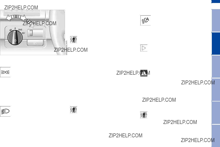
Parking lamps/Low beams
93
Parking lamps
The front, rear and side vehicle lighting is switched on. You can use the parking lamps to signal
the position of the vehicle when it is parked. For lighting on one side for parking as an additional feature, refer to page 94.
Low beams
When the ignition is switched off while the low beams are on, the headlamps go out and only the
parking lamps remain on.
Follow me home lamps
When you activate the headlamp flasher after parking the vehicle with the lamps turned off, the
You can also have this function deactivated.<
LIGHTS ON warning
When you open the driver's door, after having turned the ignition key to posi- tion 0, you will hear an acoustic signal for a few seconds to remind you that the lamps have not been switched off.
Daytime driving lamps*
If you desire, the lamp switch can be left in the second position: when the ignition is switched off, the external lighting is also switched off.
You can have the activation set- tings for the daytime driving lamps
programmed on your vehicle.<
Automatic headlight control*
When the switch is set to this position the system automati- cally activates and cancels the
low beams in response to changes in ambient light ??? in tunnels, at dusk, etc. ??? and in the event of rain and snow.
The vehicle's external lights remain on constantly when you
switch on the front fog lamps after the headlights have come on automati- cally.<
Automatic headlight control can- not serve as a substitute for the
driver's judgement in determining when the vehicle lights should be switched on. For example, the sensors are not able to detect fog. To avoid safety risks, you should respond to these kinds of
You can have the sensitivity of your vehicle's automatic head-
light control adjusted.<
 Repairs Maintenance Controls Overview
Index Data

Turn the rotary dial to adjust the illumi- nation intensity.
1High beams ??? blue indicator lamp
2Headlamp flasher ??? blue indicator lamp
3Standing lamps
Standing lamps, left or right
As an additional feature, you can illumi- nate your vehicle on either side for parking:
In ignition key position 0, engage the lever in the appropriate

Fog lamps*
Front fog lamps
The green indicator lamp in the instrument cluster lights up to indicate that the front fog lamps
are on.
If the automatic headlight control is on, the low beams will come on
automatically whenever you activate the front fog lamps.<
Interior lamps
The interior lamps operate automati- cally.
To switch the interior lamps on and off manually
Press button 1 briefly:
If you want the interior lamps to remain off all the times, press and hold the but- ton for approx. 3 seconds.
Press the button briefly to revert to nor- mal operation.
Front reading lamps*
Switch on and off with the button 2 adjacent to each lamp.
95
Rear reading lamps
Switch on and off with the button adja- cent to each lamp.
In order to prevent battery dis- charge, all of the lamps in the
vehicle are automatically switched off approx. 15 minutes after you turn the ignition key to position 0.<
Do not remove the protective lens and avoid staring directly at the
unfiltered beam for several hours, as inflammation of the retina could result.<
 Repairs Maintenance Controls Overview
Index Data

96 Air conditioning

Air conditioning
1 Air onto the windshield and the side windows
2 Air for the upper body area 99
3Air to the footwell
4Air supply/Blower 98
5Temperature 98
6Air distribution 98
7Rear window defroster 98
8Air conditioning 98
9Outside
97
 Repairs Maintenance Controls Overview
Index Data

98 Air conditioning
Air supply/Blower
You can select blower speeds from 1 to 4. The heating and ventilation become more and more effective as the air sup-
ply settings are increased. In position 0, the blower and the heater are switched off. The outside air supply is blocked in position 0.
Temperature
In order to increase the tem- perature of the passenger compartment, turn to the right, red. The temperature of
the incoming air is kept constant.
Air distribution
You can direct air to flow onto the windows  , toward your upper body
  or into the footwell
  . All intermediate
settings are possible. In the setting  , there is a low flow of air onto the win- dows to keep them free of condensa- tion.
Rear window defroster
When the rear window defroster is activated, the indicator lamp
comes on. The rear window defroster switches off automatically.
You can have your vehicle pro- grammed in such a way that the
rear window defroster switches on automatically. This occurs within 5 min- utes after starting the engine when out- side temperatures are below approx. 397/+46.<
Air conditioning
The air is cooled and dehumidi- fied and ??? depending on the
temperature setting ??? rewarmed.
Depending on the weather, the wind- shield may fog over briefly when the engine is started. Switching on the air conditioning will reduce condensation forming on the windows.
Condensation forms during opera- tion of the air conditioning system, which then exits under the vehicle. It is
thus not unusual for a small puddle to form under the car while the system is running.<
Outside
You can respond to unpleasant external odors by temporarily
excluding the supply of outside air. The system then recirculates the air cur- rently within the vehicle.
If the windows should fog over in the
ply as required.<
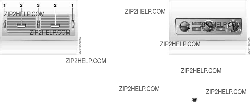
Air conditioning
You can adjust the blower controls for the upper body area to obtain the opti- mum airflow rates and directions for your personal requirements:
1Rotary dials for infinitely variable opening and closing of the vent out- lets
2Selector levers for airflow direction
3Rotary dial allows you to control the temperature of the airflow from these outlets as desired
Microfilter
The
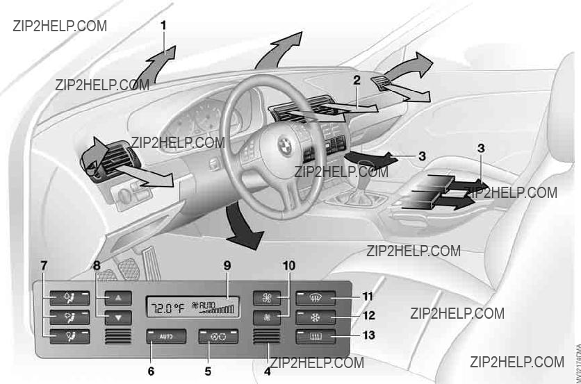
100 Automatic climate control*
Automatic climate control*
1Air onto the windshield and the side windows
2Air for the upper body area 103
3Air to the footwell 103
4Air inlet for interior temperature sensor ??? please keep clear and unobstructed
5Outside air/Automatic recirculated- air control (AUC)/Recirculated
air 103
6Automatic air distribution 102
7Individual air distribution 102
8Temperature 102
9Display for temperature 102 and air supply 102
10Air supply/Blower 102
11To defrost windows and remove condensation 102
12Air conditioning 102
13Rear window defroster 103
101
 Repairs Maintenance Controls Overview
Index Data

102 Automatic climate control*
Tips for pleasant driving
Use the automatic mode by pressing AUTO button 6. Select an interior tem- perature that is comfortable for you.
Detailed setting options are described for you in the following section.
You can make the settings of your vehicle in such a manner that
when you unlock the vehicle with the remote control of your personal key, your own personalized setting for the automatic climate control is initiated.<
Automatic air distribution and supply
The AUTO program adjusts the air distribution and the air sup-
ply for you and in addition adapts the temperature to external influences ??? summer, winter ??? to meet preferences you can specify.
Individual air distribution
You can cancel the AUTO pro- gram by selecting specific dis- tribution patterns to suit your own individual requirements.
While the AUTO program is then deacti- vated, the automatic airflow control remains in operation. Air flows onto
windows  , toward the upper body
  , and into the footwell
  . You can
switch the automatic distribution of air back on by selecting the AUTO button.
Temperature
The interior temperature that appears in the display panel is a general figure intended for refer-
ence purposes. We recommend
727/+226 as a comfortable setting, even if the air conditioning is on. When you start the vehicle, the system ensures that the selected temperature is achieved as quickly as possible regardless of the season. It then main- tains this temperature.
To select the units of measure 6/7 of the display, refer to page 83.
Air supply/Blower
By pressing the upper or lower button, you can vary the air sup- ply. This deactivates the auto-
matic control of the air supply, AUTO disappears from the display panel. Nev- ertheless, the automatic air distribution remains unchanged. You can reactivate the automatic air distribution mode by selecting the AUTO button.
When the lowest blower speed is set and you press the lower button, all of the displays are canceled: the blower, heating and air conditioning are switched off. The outside air supply is blocked. You can reactivate the system by pressing any button for the auto- matic climate control.
To defrost windows and remove condensation
This program quickly removes ice and condensation from the
windshield and the side windows.
Air conditioning
The air is cooled and dehumidi- fied and ??? depending on the
temperature setting ??? rewarmed.
Depending on the weather, the wind- shield may fog over briefly when the engine is started. Air conditioning helps prevent the windows from fogging up.
Condensation forms during opera- tion of the air conditioning system, which then exits under the vehicle. It is
thus not unusual for a small puddle to form under the car while the system is running.<

Automatic climate control*
103
Outside air/Automatic
You can respond to unpleasant external odors or pollutants by temporarily stopping the flow of outside air. The system then recirculates the air
currently within the vehicle.
Press the button repeatedly to select one of three different operating modes.
>Indicator lamps off: outside air supply is on
>Left indicator lamp on ??? AUC mode: the system recognizes pollutants in the outside air and blocks the flow of air when necessary. The system then recirculates the air currently within the vehicle. Depending on the air quality, the automatic system then switches back and forth between outside air supply and recirculation of the air within the vehicle
>Right indicator lamp on: the flow of external air into the vehicle is perma- nently blocked. The system then recirculates the air currently within the vehicle.
If the windows should fog over in the
ply as required.<
Rear window defroster
When the rear window defroster is activated, the indicator lamp
comes on. The rear window defroster switches off automatically.
You can have your vehicle pro- grammed in such a way that the
rear window defroster switches on automatically. This occurs within 5 min- utes after starting the engine when out- side temperatures are below approx. 397/+46.<
You can adjust the blower controls for the upper body area to obtain the opti- mum airflow rates and directions for your personal requirements:
1Rotary dials for infinitely variable opening and closing of the vent out- lets
2Selector levers for airflow direction
3Rotary dial allows you to control the temperature of the airflow from these outlets as desired
 Repairs Maintenance Controls Overview
Index Data
104 Automatic climate control*
The
Premium sound system*
Harman Kardon premium sound system
Press the button to activate and deacti- vate the acoustic enhancement.
The system creates the acoustic impression of a much larger passenger compartment accompanied by improved stereophonic sound at all seating positions.
The system responds to poor reception conditions by repeatedly alternating between the stereo and monophonic modes. You should then switch the sys- tem off.
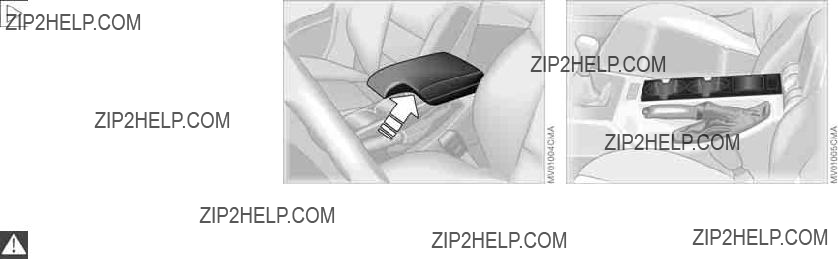
If ??? for example for valet parking ??? you turn over only your spare key,
refer to page 30, then access to the locked glove compartment is not possi- ble.<
Rechargeable flashlight
The flashlight is located on the left side of the glove compartment.
It features integral overload protection, so it can be left in its holder continu- ously.
To avoid completely discharging and possibly damaging the flash- light, always ensure that it is switched
off before inserting it in the socket.<
Front center armrest
To open: press the button and fold up.
Additional compartments and nets*
You will find additional storage com- partments in the front doors and in the center console. Storage nets are on the front seat backrests.
Beverage holders, coin box
A coin box and two beverage holders are provided in the center console.

Storage compartments
Rear center armrest
The rear center armrest includes a stor- age compartment, a beverage holder and a litter bag holder.
1Storage compartment: pull up
2Beverage holder: press
Storage package*
For your convenience, there are:
>Two
>An eyeglasses compartment*, not shown, in the front center console.
On vehicles that are wired for a tele- phone* or equipped with a communica- tions package*, the cover for the handsfree microphone is located in the headliner near the interior lamp.
For further information on using your cellular phone, refer to the Owner's Manual for the telephone.
 Repairs Maintenance Controls Overview
Index Data

Cigarette lighter socket
Suitable for attaching power supplies for flashlights, car vacuum cleaners, etc., up to a rating of approx. 200 watts at 12 volts. Avoid damage to the socket caused by inserting plugs of different shapes or sizes.
To empty
Press on the edge of the open cover: the ashtray moves up and can be removed.
Cigarette lighter
Hold or touch the hot cigarette lighter by the knob only. Holding
or touching it in other areas could result in burns.
The cigarette lighter remains opera- tional when the ignition key has been removed. For this reason, children should never be left in the vehicle unat- tended.<
Press the lighter 1 in. You can remove the lighter from its socket for use as soon as it snaps back out.
To empty
Press on the edge of the open cover in the opening direction. The ashtray moves up and can be removed.

Socket
A
109
 Repairs Maintenance Controls Overview
Index Data

110 Ski bag*
The ski bag allows the safe and clean transport of up to 4 pairs of standard skis or up to two snowboards.
The length of the ski bag and the addi- tional space provided in the cargo area make it possible to carry skis up to
6 ft 10 in / 2.10 m long. Because of the tapered shape of the bag, only two pairs of skis longer than 6 ft 10 in / 2.10 m can be carried.
Loading
1.Fold the center armrest outward. Loosen the trim from the upper Velcro?? fastener and place it on the armrest
2.Press the button ??? see arrow 1, from inside the passenger compartment: the cargo hatch drops onto the floor of the cargo area
3.Press down the detent lever ??? see arrow 2 ??? and fold the cover forward
4.Extend the ski bag between the front seats. The zipper provides conve- nient access to stored items. It may be opened to allow the ski bag to dry.
To store the ski bag, perform the above steps in reverse sequence.
Securing cargo
Secure skis and any other objects stored in the bag by tightening the
retaining strap at the buckle.<
Be sure that your skis are clean before loading them into the bag.
Avoid damage from sharp edges during loading.<
Cargo area
111
Folding rear backrest
Reach into the recess and pull forward.
When you fold back the backrest, be sure that the catch engages
securely. The red warning indicator in the recess disappears when the retainer is locked.<
Cargo area cover
Never use the cover to carry heavy or hard objects, as such
objects could pose a hazard to the vehicle's occupants during sudden braking maneuvers.
Guide the cover back into place; do not allow it to snap back, as it could sustain damage.<
Pull out the cover and suspend it by attaching it to the holders.
You can carry light objects such as arti- cles of clothing on the cover.
Partition net*
Use the loop to pull out the partition net, then grasp both sides of the rod and insert it into its holder. It is easiest to do this from the back seat.
Do not allow the partition net to snap back. Doing so could pose a
risk of injury and the partition net could be damaged.<
If the backrests are folded forward, the partition net's case can be stored on the backrests; you can then extract the partition net and hold it in place by inserting the retainers into the front holders, refer to next page.
 Repairs Maintenance Controls Overview
Index Data
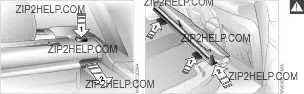
112 Cargo area
To ensure that the case is properly positioned, remember to insert it
on both guides from the right side, always continuing until the detents snap into place. Failure to observe the prescribed insertion procedure could also result in damage to the door's upholstery.<
To remove cargo cover and partition net
1.Press the buttons on the sides ??? see arrow 1
2.Extract the case by pulling to the rear
??? see arrow 2.
Installation
Simply slide the case forward in the two side holders until it engages.
Storing with backrests folded forward
Supports for the case are provided on the rear sides of the backrests ??? see arrow 1.
Insert the case from the right as shown in the illustration, continuing until the detent engages ??? see arrow 2. Ensure that the cargo cover points toward the front of the vehicle, with the partition net's loop on the top.
You can pull the partition net out and insert it into the holders above it in the upper roof area.

Cargo area
Avoid overloading the vehicle so that the permitted load on the tires
is not exceeded. Overloading can lead to overheating and internal tire damage. The ultimate result can assume the form of a sudden air loss.<
 Controls Overview
Lifting the floor panel
1.Lift up the floor panel slightly at loop 1
2.Release the loop end from the under- side of the floor panel
3.Hook the loop end with the tab onto the rubber
Before folding the floor panel back down, attach the loop end to the
holder on the underside of the floor panel.<
Side covers
Open the side covers by pressing the button.
Repairs Maintenance
Index Data

114 Cargo loading
Determining the maximum load
1.Locate the following statement on your vehicle???s placard*:
The combined weight of occu- pants and cargo should never
exceed XXX kg or YYY lbs., as this could otherwise result in damage to the vehicle or unstable driving conditions.<
2.Determine the combined weight of the driver and passengers that will be riding in your vehicle
3.Subtract the combined weight of the driver and passengers from
XXX kilograms or YYY pounds
4.The resulting figure equals the avail- able amount of cargo and luggage load capacity.
For example, if the XXX amount equals 1,400 lbs. and there will be five 150 lbs. passengers in your vehi- cle, the amount of available cargo and luggage load capacity is
650 lbs.:
1,400 lbs. minus 750 lbs. = 650 lbs.
5.Determine the combined weight of luggage and cargo being loaded on the vehicle. That weight may not safely exceed the available cargo and luggage load capacity calculated in Step 4
6.If your vehicle will be towing a trailer, load from your trailer will be trans- fered to your vehicle. Consult the manual for transporting a trailer to determine how this may reduce the available cargo and luggage load capacity of your vehicle.
Stowing cargo
>Load heavy cargo as far forward as possible ??? directly behind the back- rests or the cargo area partition ??? and as low as possible
>Cover sharp edges and corners
>Do not pile objects higher than the top edge of the backrest
>Pull out the partition net*, refer to previous page, taking care to ensure that there is no danger that any of the objects stored in the cargo area will protrude through the net*
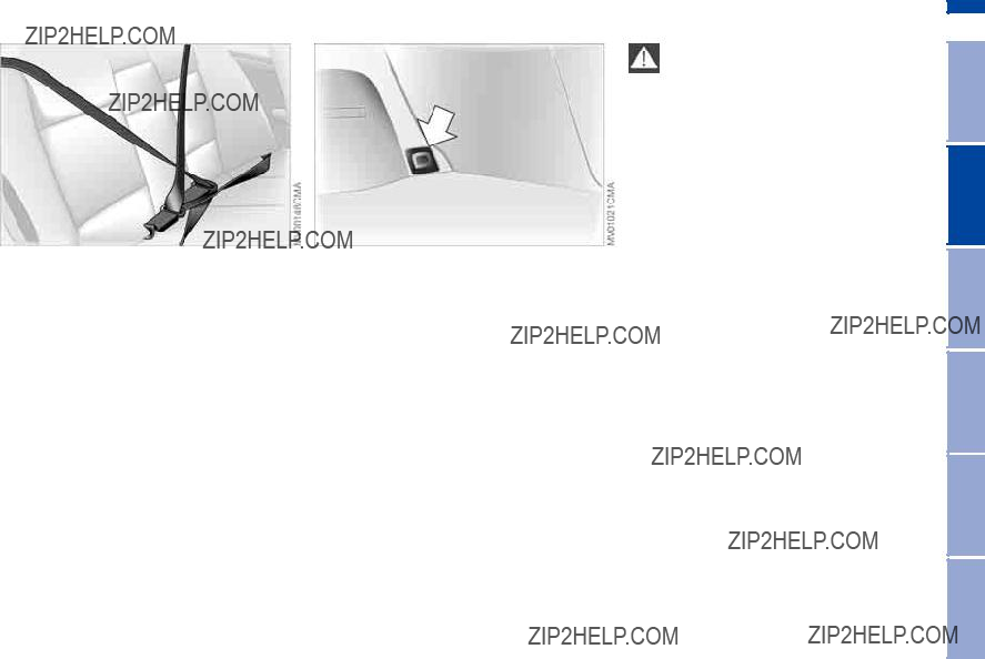
Cargo loading
>For very heavy loads when the rear seat is not occupied, secure each safety belt in the opposite buckle.
Securing cargo
>Small and light luggage and cargo can be secured with the aid of flexi- ble straps or a luggage compartment net*, refer to page 37
>For large, heavy pieces, see your BMW center for
Read and comply with the instructions enclosed with the
115
Always position and secure loads correctly. If you do not, the load
can endanger the passengers during braking or evasive maneuvers.
Do not exceed the approved gross vehicle weight or the approved axle loads, refer to page 162, otherwise the vehicle's operating safety is no longer assured and the vehicle will not be in compliance with the certification regu- lations.
Do not stow heavy or hard objects in the passenger compartment without securing them. Otherwise they would be thrown around during braking and evasive maneuvers and could endanger the passengers.<
 Repairs Maintenance Controls Overview
Index Data
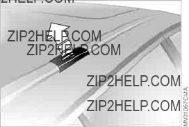
116
A special
Anchorages
Access to the anchorages:
To fold up the covers, please use the tool provided with the
Loading and driving notes
You should therefore always remember not to exceed the approved roof load capacity, the approved gross vehicle weight or the axle loads when loading the rack. These weights are listed under Technical data on page 162.
Make sure that the load is not too bulky, and attempt to distribute it evenly. Always load the heaviest pieces first so that they are at the bottom. Be sure that adequate clearance is maintained for raising the glass sunroof, and that objects do not project into the opening path of the tailgate.
Secure the
Drive smoothly and avoid sudden acceleration and braking. Do not corner at high speeds.
The
117
118

119
Overview
Controls and features
Operation, maintenance
Owner service procedures
Technical data
Index
 Repairs Maintenance Controls Overview
Index Data

120
To ensure that your vehicle provides maximum economy throughout a long service life, we request that you observe the following suggestions.
Engine and differential
Up to 1,250 miles/2,000 km:
Constantly vary both vehicle and engine speeds, remembering not to exceed 4,500 rpm or vehicle speeds of over 100 mph / 160 km/h:
Obey your local and state maximum speed limits.
Do not use full throttle, and avoid pressing the accelerator beyond the kickdown point during these initial miles.
You can then proceed to increase engine or vehicle speeds once the ini- tial 1,250 miles/2,000 km have elapsed.
You should also observe the same
Tires
Due to technical factors associated with their manufacture, tires do not achieve their full traction potential until an initial
Obey your local and state maximum speed limits.
When the vehicle is operated on wet or slushy roads, a wedge of water may form between the tire and the road surface. This phenomenon is
referred to as hydroplaning, and can lead to partial or complete loss of trac- tion, as well as loss of vehicle control and braking effectiveness. Reduce your speed on wet roads.<
Brake system
Approx. 300 miles/500 km must elapse before the brake pads and rotors achieve the optimal
To break in the separate parking brake drums, apply the parking brake lightly when coasting to a standstill ??? at a traf- fic signal, for instance ??? provided that traffic conditions allow you to do so.
To avoid corrosion, repeat this proce- dure from time to time.
The brake lamps do not come on when the parking brake is set.
Vacuum for the brake system servo unit on your BMW is available only when the engine is running. When you move the vehicle with the engine off ??? when tow- ing, for example ??? substantially higher levels of pedal force will be required to brake the vehicle.<
Clutch
Approx. 300 miles/500 km must elapse before the clutch starts to operate at optimum efficiency. Remember to engage the clutch carefully during this initial period.
Brakes: do not rest your foot on the brake pedal while driving.
Even light but consistent pedal pres- sure can lead to high temperatures, brake wear and possibly even brake failure.
Hydroplaning: when driving on wet or slushy roads, reduce road speed. If you do not, a wedge of water can form between tires and road surface. This phenomenon can lead to partial or complete loss of contact between the tires and road surface, as well as loss of vehicle control and braking ability. Driving through water: do not drive through water on the road if it is deeper than 1 ft/30 cm, and then only at walk- ing speed. Otherwise, the vehicle's engine, the electrical systems and the transmission may be damaged.
Cargo area cover: never use it to store heavy or hard objects; otherwise, occu- pants could be injured if the vehicle is braked hard.
Clothes hooks: when hanging clothing from the hooks, be sure that they will not obstruct the driver's vision. Do not hang heavy objects on the hooks. If you do so, they could cause personal injury during braking or evasive maneuvers.<
The concept
ABS keeps the wheels from locking during braking, thereby enhancing active driving safety.
Braking with ABS
If you are in a situation that requires full braking, you will exploit the full benefits of ABS system if you apply maximum pedal pressure ??? panic stop. Since the vehicle maintains steering responsive- ness, you can avoid possible obstacles with a minimum of steering effort, despite the full brake application.
Pulsation at the brake pedal combined with sounds from the hydraulic circuits indicates to the driver that ABS is in its active mode.
Dynamic Brake Control (DBC)
DBC is included in the DSC, refer to page 86.
The system responds to sudden, high- intensity applications of force to the brake pedal by automatically braking the vehicle with maximum boost to achieve the shortest possible braking distances during panic stops. This sys- tem exploits all the benefits of ABS.
Do not reduce the pressure exerted against the brake pedal until the brak- ing maneuver has been completed. DBC is deactivated when you release the brake pedal.
Cornering Brake Control (CBC)
CBC is an advanced engineering design of the ABS. When braking while cornering at high speed or braking dur- ing high lateral acceleration, or when braking during a lane change, vehicle stability is improved and steering response is enhanced.
Repairs Maintenance Controls Overview
Index Data

122 Brake system
Brake fluid level
Low brake fluid level in the reservoir combined with longer than usual pedal travel may indicate a defect in one of the brake system's hydraulic circuits.
Proceed to the nearest BMW cen- ter. It may be necessary to apply
higher levels of pressure to the pedal when stopping and braking distances may also be longer. Please remember to adapt your driving style accord- ingly.<
Disc brakes
When the vehicle is driven only occa- sionally, during extended periods when the vehicle is not used at all, and in operating conditions where brake appli- cations are less frequent, there is an increased tendency for corrosion of the rotors and accumulation of contamina- tion on the brake pads. This occurs because the minimal pressure that must be exerted by the pads to clean the rotors by brake applications is not reached.
Corrosion on brake rotors is signaled by a running or pulsation during braking; even extended subsequent braking will not cure this phenomenon.
It is a good idea to periodically dry the brakes with a gentle application when driving in rain and on wet roads. Watch traffic conditions to ensure that this maneuver does not endanger other road users. The heat generated in this process helps dry the pads and rotors to ensure that your brake system will respond with undiminished efficiency when you need it.
When descending steep hills and extended grades, downshift to a gear that will allow you to continue safely with only a minimal amount of braking. This helps avoid placing excessive loads on the brake system. Use care to avoid exceeding the approved engine- speed range, refer to page 79.
Do not coast with the clutch depressed or with the transmis-
sion or selector lever in Neutral. Do not coast with the engine shut off. The engine provides no braking effect when the clutch is depressed and there is no
325xi: always refer all brake inspection and service work to your BMW center, as failure to observe the special proce- dures could result in damage to com- ponents of the
Never allow floor mats, carpets or any other objects to protrude into the area around the accelerator, clutch and brake pedals and obstruct their move- ment.<
Brake pads
For your own safety: use only brake pads which BMW has
approved for your specific vehicle model. BMW cannot evaluate non- approved brake pads to determine if they are suitable for use, and therefore cannot ensure the operating safety of the vehicle if they are installed.<

Brake system
Portable phone in the vehicle
BMW recommends using mobile com- munications devices, e.g. portable phones, inside the vehicle with a suit- able outside antenna. Otherwise, it can- not be ruled out that the vehicle elec- tronics and portable phone may interfere with each other.
123
 Repairs Maintenance Controls Overview
Index Data
Information for your safety
The
It is not merely the tire's service life, but also driving comfort and ??? above all else
??? driving safety that depend on the con- dition of the tires and the maintenance of the specified tire inflation pressure.
Incorrect tire inflation pressure is a fre- quent cause of tire damage. It also sig- nificantly influences the roadholding ability of your BMW.
Be sure to check the tire inflation pressure, including the space-
saver spare tire or the spare tire, on a regular basis, at least twice a month and before every extended journey, refer to page 25. If this is not done, incorrect tire pressures can cause driv- ing instability and tire damage, ulti- mately resulting in accidents.<
Tire tread ??? tire damage
Inspect your tires frequently for tread wear, signs of damage and for foreign objects lodged in the tread. Check the tread depth.
Tread depth should not be allowed to go below 1/8 in / 3 mm, even though the legally specified minimum tread depth is 1/16 in / 1.6 mm.
Below 1/8 in / 3 mm tread depth, there is a great risk of hydroplaning, even at relatively moderate speeds and with only small amounts of water on the road. Tread wear indicators ??? see arrow
??? are embedded in the base of the tire's tread. Their locations are indicated by the letters TWI ??? Tread Wear Indicator ??? at various points on the tire's shoulder.
When the tread reaches a depth of 1/16 in / 1.6 mm, these indicators appear and signal that the tires have worn to the minimum legal level.

Tire condition
Do not drive on a deflated ??? flat ??? tire unless your vehicle is
equipped with Run Flat tires. A flat tire greatly impairs steering and braking response, and can lead to complete loss of control over the vehicle.
Avoid overloading the vehicle so that the permitted load on the tires is not exceeded. Overloading can lead to overheating and internal tire damage. The ultimate result can assume the form of a sudden air loss.
Unusual vibrations encountered during normal vehicle operation can indicate a damaged tire or some other vehicle malfunction. This type of problem can be caused by contact with curbs, etc. This is also true for irregularities in the vehicle's handling characteristics, such as a pronounced tendency to pull to the left or right. Should this occur, respond by immediately reducing your speed. Proceed carefully to the nearest BMW center or professional tire center, or have the vehicle towed in to have it, its wheels or its tires inspected.
Tire damage, up to and including sud- den and complete air loss, can endan- ger the lives of both the vehicle occu- pants and other road users.<
Tire replacement
To maintain good handling and vehicle response, use only tires of a single tread configuration from a single manu- facturer.
Comply with the specified tire inflation pressures ??? and be sure to have the wheel and tire assembly balanced every time you change a tire or wheel.
DOT quality grades
Tread wear
Traction AA A B C
Temperature A B C
All passenger car tires must con- form to Federal Safety Require-
ments in addition to these grades.<
Tread wear
The tread wear grade is a comparative rating based on the wear rate of the tire when tested under controlled condi- tions on a specified government test course.
For example, a tire graded 150 would wear one and

126 Tire replacement
Sustained high temperature can cause the material of the tire to degenerate and reduce tire life, and excessive tem- perature can lead to sudden tire failure. The grade C corresponds to a level of performance which all passenger car tires must meet under the Federal Motor Vehicle Safety Standard No. 109. Grades B and A represent higher levels of performance on the laboratory test wheel than the minimum required by law.
The temperature grade for this tire is established for a tire that is
properly inflated and not overloaded. Excessive speed, underinflation, or excessive loading, either separately or in combination, can cause heat buildup and possible tire failure.<
Uniform Tire Quality Grading
Quality grades can be found where applicable on the tire sidewall between tread shoulder and maximum section width. For example:
Tread wear 200
Traction AA
Temperature A
BMW advises against using retreaded tires, since driving
safety may be impaired. This is due to the possible variations in casing struc- tures and, in some cases, to their extreme age, which can lead to a decrease in their durability.<
Tire age
The date on which the tire was manu- factured is indicated by the code on the sidewall:
DOT... 3603 indicates that the tire was manufactured in week 36 of the year 2003.
BMW recommends the replacement of all tires ??? including the spare tire* ??? when the tires are no more than 6 years old, even if a tire life of 10 years is pos- sible.
Run Flat tires*
Before purchasing tires, check if your BMW is equipped with Run Flat tires. These are indicated by a circular sym- bol containing the letters RSC on the tire sidewall, refer to Changing a wheel. In this case, use only Run Flat tires, since no spare wheel is available in the event of a flat. For more information on Run Flat tires, refer to page 150.
Run Flat tires are available only in combination with the Flat Tire
Monitor.<

The right choice
BMW recommends using only wheels and tires that have been
approved by BMW for your particular vehicle model, as otherwise body con- tact and serious accidents can result despite the use of the same nominal size, e.g. due to manufacturing toler- ances. BMW cannot evaluate all tires and wheels on the market, and is thus unable to guarantee that the vehicle will continue to perform safely if unap- proved tires and/or wheels are mounted.<
For each tire size, BMW has assessed the safe performance of specific tire brands and approved them for use. Consult any BMW center for details. Comply with any local/national regula- tions, for example by recording the tire type in the vehicle documents.
The correct
as ABS, DSC and
Storage
Always store tires in a cool, dry place. Store them away from light whenever possible. Protect the tires against con- tact with oil, grease and fuel.
Do not exceed the maximum tire infla- tion pressures specified on the tire sidewall.
Choosing the right tire
BMW recommends the use of winter tires for operation under winter road conditions. While
In the interest of safe tracking and steering response, install winter tires made by the same manufacturer and having the same tread configuration on all four wheels.
Never exceed the maximum speed for which the winter tires
are rated.
Unprofessional attempts by laymen to service tires can lead to damage and accidents.
Have this work performed by trained professionals only. Any BMW center has the required technical knowledge and the proper equipment and will be happy to assist you.<
Run Flat tires*
Before purchasing winter tires, check if your BMW is eqipped with Run Flat tires. These are indicated by a circular symbol containing the letters RSC on
 Repairs Maintenance Controls Overview
Index Data

128 Winter tires
the tire sidewall, refer to Changing a wheel. In this case, use only Run Flat winter tires, since no spare tire is pro- vided in the event of a flat tire.
Tire condition, tire pressure
At tread depths below approx. 3/16 in / 4 mm, winter tires display a perceptible decrease in their ability to cope with winter driving conditions, and should be replaced in the interest of safety.
Comply with the specified tire inflation pressures ??? and be sure to have the wheel and tire assembly balanced every time you change a tire or wheel.
Snow chains*
Only certain snow chains have been tested by BMW and determined and approved as roadworthy. Consult any BMW center for details. BMW recom- mends using only these approved fine- link snow chains. Use them in pairs on either summer or winter tires, but only on both rear wheels.
325xi: in an extreme emergency ??? for instance, with the vehicle stuck on one side, or when obstructions make it impossible to reach one tire ??? a chain may also be mounted on just one tire for the limited period needed to resolve the problem.
Comply with all manufacturer's safety precautions when mounting the chains. Do not exceed a speed of 30 mph /
50 km/h when using snow chains.
You cannot mount snow chains on the following tires:
225/50 R 16
225/45 R 17
245/40 R 17
225/40 R 18
255/35 R 18
Do not initialize the Flat Tire Moni- tor after mounting snow chains to
the tires.
When driving with snow chains, it may be useful to turn off the DSC for a short time, refer to page 87 or 88.<

Hood
To release
Pull the lever located under the left- hand side of the instrument panel.
Do not attempt to service your vehicle if you do not have the
required technical background. Failure to work in an informed, professional manner when servicing components and materials constitutes a safety haz- ard for vehicle occupants and other road users. If you are not familiar with the guidelines, BMW recommends that you have the operations performed by your BMW center.<
To open
Pull the release handle and open the hood.

130 Engine compartment essentials
Engine compartment essentials
1 Brake fluid reservoir 135
2 Dipstick, engine oil 132
3 Coolant expansion tank 134
4Reservoir for the headlamp and windshield washer system 132
5Engine oil filler neck 132
6Auxiliary terminal for jump- starting 153
131
 Repairs Maintenance Controls Overview
Index Data
Headlamp* and windshield washer system
Capacity approx.
5.6 US quarts/5.3 liters.
Fill with water and, if required, with a washer antifreeze additive according to manufacturer's recommendations.
We recommend that you mix the washer fluid before adding it to
the reservoir.<
Rear window washer reservoir
Capacity approx.
2.4 US quarts/2.3 liters.
Fill with water and, if required, with a washer antifreeze additive according to manufacturer's recommendations.
We recommend that you mix the washer fluid before adding it to
the reservoir.<
Antifreeze agents for the washer fluid are highly flammable. For this
reason, keep them away from sources of flame and store them only in their closed original containers. Store it inac- cessible to children. Comply with the instructions on the containers.<
Checking the oil level
1.Park the vehicle on a level surface
2.Switch the engine off after it has reached normal operating tempera- ture
3.After approx. 5 minutes, pull the dip- stick out and wipe it off with a clean
4.Carefully push the dipstick all the way into the guide tube and pull it out again
5.The oil level should be between the two marks on the dipstick.
As with fuel economy, oil consumption is directly influenced by your driving style and vehicle operating conditions.

Engine oil
The oil volume between the two marks on the dipstick corresponds to approx. 1.1 US quarts/1 liter. Do not fill beyond the upper mark on the dipstick. Excess oil will damage the engine.
Adding engine oil
Only add engine oil when the oil level has dropped to just above the lower mark on the dipstick.
BMW engines are designed to operate without oil additives; the
use of additives could lead to damage in some cases. This also applies to the manual transmission, the automatic transmission, the differential, and the power steering system.<
Recommendation: have the oil changed by your BMW center.
133
Continuous exposure to used oil has caused cancer in laboratory testing. For this reason, any skin areas that come into contact with oil should
be thoroughly washed with soap and water.
Store oils, grease and similar materials so that they are inaccessible to chil- dren. Comply with warning labels and information on containers.<
Comply with the applicable envi- ronmental laws regulating the dis-
posal of used oil.<
Specified engine oils
The quality of the engine oil is extremely important for the function and service life of an engine. Based on extensive testing, BMW has approved only certain grades of engine oil.
Use only approved BMW High Perfor- mance Synthetic Oil.
If an approved BMW High Performance Synthetic Oil should be unavailable, you may use small volumes of other syn- thetic oils for topping up between oil changes. Use only oils with the specifi- cation API SH or higher.
 Repairs Maintenance Controls Overview
Index Data

Ask your BMW center for details concerning the specific BMW
High Performance Synthetic Oil or syn- thetic oils that have been approved.<
You can also call BMW of North Amer- ica
Viscosity ratings
Viscosity is the oilflow rating as estab- lished in SAE classes.
The selection of the correct SAE class depends on the climatic conditions in the area you drive your BMW.
Approved oils are in SAE classes
These kinds of oil may be used for driv- ing in all ambient temperatures.
Do not add coolant to the cooling system when the engine is hot. If you attempt to do so, escaping coolant
can cause burns.
Antifreeze and
Comply with the applicable envi- ronmental laws regulating the dis-
posal of antifreeze agents with corro- sion inhibitor.<
Checking the coolant level and adding coolant
Check the coolant level when the engine is cold, approx. 687/+206:
1.Open the cap for the expansion tank by turning it slightly counterclock- wise to allow accumulated pressure to escape, then open
2.The coolant level is correct when the upper end of the red float is at least even with the upper edge of the filler neck; see arrow. The end of the float may stick out by a maximum of
3/4 in / 2 cm ??? that is, up to the sec- ond mark on the float
3.If necessary, add coolant. If the cool- ant is low, slowly add coolant until the correct level is reached ??? do not overfill.

Brake fluid
135
Indicator lamp
The brake warning lamp comes on when the parking brake is not engaged: the brake fluid
level is too low, refer to page 18.
Brake warning lamp for Cana- dian models.
Adding brake fluid
For adding brake fluid or for determin- ing and correcting the cause of brake fluid loss, consult your BMW center.
Your BMW center is familiar with the specifications for
Brake fluid loss results in extended brake pedal travel. Refer to the informa- tion on page 122.
Brake fluid is hygroscopic, that is, it absorbs moisture from the air
over time.
In order to ensure the brake system's safety and reliability, have the brake fluid changed every two years by a BMW center. Refer to the Service and Warranty Information Booklet for US models or the Warranty and Service Guide Booklet for Canadian models. Brake fluid is toxic and damages the vehicle's paint. You should always store it in its closed original container and in a location which is out of reach of chil- dren.
Do not spill the brake fluid and do not fill the brake fluid reservoir beyond the MAX mark. The brake fluid could ignite upon contact with hot engine parts and cause serious burns.<
Comply with the applicable envi- ronmental laws regulating
the disposal of brake fluid.<
 Repairs Maintenance Controls Overview
Index Data

136 The BMW Maintenance System
The BMW Maintenance System has been designed as a reliable means of providing maximum driving and operat- ing safety ??? and as
Please keep in mind that regular main- tenance is not only necessary for the safety of your vehicle, but also plays a significant role in maintaining the resale value of the vehicle.
Service interval display
While conventional systems rely on dis- tance traveled alone to determine when service is due, the BMW Maintenance System has for years taken the actual conditions under which the vehicle operates into consideration, because miles can be traveled in many different ways:
From a maintenance point of view, 62,000 miles/100,000 km of
The BMW Maintenance System includes the Engine Oil Service and Inspections I and II.
Determining the maintenance intervals according to the actual use of the vehi- cle covers every kind of operating situa- tion. Minimal use drivers ??? those who drive significantly fewer than
6,200 miles/10,000 km annually ??? should have the engine oil changed at least every 2 years since oil deterio- rates over time, regardless of use.
Service and Warranty Information Booklet for US models/
Warranty and Service Guide Booklet for Canadian models
For additional information on required maintenance intervals and procedures, please refer to the Service and War- ranty Information Booklet for US mod- els, or the Warranty and Service Guide Booklet for Canadian models.
As a precaution against corrosion, it is advisable to have the body checked for damage from rocks or gravel at the same time, depending upon operating conditions.

The BMW Maintenance System
Have your BMW center perform maintenance and repair.
Be sure that all maintenance work is recorded in the Service and Warranty Information Booklet for US models, or in the Warranty and Service Guide Booklet for Canadian models. These entries confirm that your vehicle has benefitted from regular maintenance, and are also required for warranty claims.<
Care
You can find everything you need to know on this topic by consulting the separate Caring for your vehicle bro- chure.
137
 Repairs Maintenance Controls Overview
Index Data

138 California Proposition 65 warning
California laws require us to state the following warning:
Engine exhaust and a wide variety of automobile components and
parts, including components found in the interior furnishings in a vehicle, con- tain or emit chemicals known to the State of California to cause cancer and birth defects and reproductive harm. In addition, certain fluids contained in vehicles and certain products of com- ponent wear contain or emit chemicals known to the State of California to cause cancer and birth defects or other reproductive harm.
Battery posts, terminals and related accessories contain lead and lead com- pounds. Wash your hands after hand- ling.
Used engine oil contains chemicals that have caused cancer in laboratory ani- mals. Always protect your skin by washing thoroughly with soap and water.<
OBD interface socket
The interface socket for onboard diag- nostics is located on the
This interface makes it possible to access data on
An illuminated indicator informs you of the need for service, not that you need to stop the vehi-
cle. Your system should be checked, however, at the earliest opportunity.
If the indicator blinks or flashes, this indicates a high level of engine misfire. Reduce speed and contact the nearest BMW center immediately. Severe

OBD interface socket
engine misfiring for even a short period of time can seriously damage emission control system components, especially the catalytic converter.
SERVICE ENGINE SOON warn- ing lamp for Canadian models.
If the gas cap is not on tight enough, the OBD system can
detect leaking vapor and the indicator will light up. If the gas cap is then tight- ened, the indicator will usually go out after a short period of time.<
139
 Repairs Maintenance Controls Overview
Index Data
140
141
Overview
Controls and features
Operation, maintenance
Owner service procedures
Technical data
Index
 Repairs Maintenance Controls Overview
Index Data

The onboard tool kit is located beneath the floor panel in the cargo area.
For information on raising the floor panel, refer to page 113.
Windshield
1.Switch off the engine
2.Fold the wiper arm completely out from the windshield
3.Position the wiper blade at an angle and pull the release spring ??? see arrow
4.Fold the wiper blade down and unhook it toward the windshield
5.Pull the wiper blade past the wiper arm toward the top
6.Insert a new wiper blade and apply pressure until you hear it engage.
Rear window
1.Switch off the engine
2.Fold the wiper arm completely out from the windshield
3.Pull out the wiper blade ??? see arrow
4.Guide the new wiper blade into place, continue to apply pressure until you hear the detent engage.

Lamps and bulbs
143
The lamps and bulbs make essential contributions to the safety of your vehi- cle. Therefore, proceed carefully when handling bulbs. BMW recommends that you have such work performed by your BMW center if you are not familiar with the procedures.
Do not touch the glass portion of a new bulb with your bare hands since even small amounts of impurities
burn in to the surface and reduce the service life of the bulb. Use a clean cloth, paper napkin, or a similar mate- rial, or hold the bulb by its metallic base.<
A replacement bulb set is available from your BMW center.
Before working on the electrical system, switch off the electrical accessory you are working on or dis-
connect the cable from the negative terminal of the battery. Failure to observe this precaution could result in short circuits.
To prevent injuries and damage, com- ply with any instructions provided by the bulb manufacturer.<
Low beams and high beams
Engine compartment, left side:
1Low beams
2High beams H7 bulb, 55 watts
The H7 bulb is pressurized. There- fore, wear safety glasses and pro-
tective gloves. Failure to comply with this precaution could lead to injury if the bulb is damaged.<
1.Turn the two release catches at the front to the left ??? see arrow ??? to remove the bulb holder
2.Remove and replace the bulb.
Insert the new bulb as shown in the inset.
When attaching the bulb holder, ensure that the lock snaps in place properly.<
When cleaning the headlamps, please follow the instructions in
the Caring for your vehicle brochure.<
Xenon lamps
The service life of these bulbs is very long and the probability of a failure is very low, provided that they are not switched on and off an unusual number of times. If one of these bulbs should nevertheless fail, it is possible to con- tinue driving with great caution using the fog lamps, provided local traffic laws do not prohibit this.
Because of the extremely high voltages involved, any work on the
xenon lighting system, including bulb- changing, should be carried out by
 Repairs Maintenance Controls Overview
Index Data
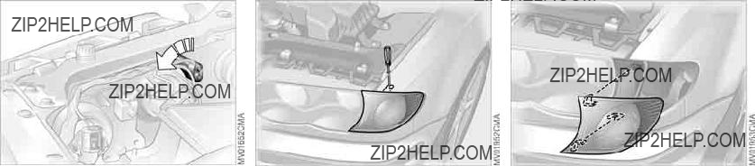
144 Lamps and bulbs
Parking lamps
5 watt bulb
Engine compartment, left side:
1.Turn the bulb holder to the left and remove
2.Remove and replace the bulb.
Front turn signal indicators
21 watt bulb
1.Extend a screwdriver through the upper opening and loosen the screw, continuing until you can extract the bulb by removing it from the front
2.Disconnect the plug
3.Apply gentle pressure and turn the bulb toward the letters AUF ??? refer to the marking on the housing??? then remove it for replacement
4.Connect the plug
5.Align the lamp assembly's two ridges and the centering pin with the guides on the vehicle when installing
6.Slide in the lamp, applying gentle pressure to seat it firmly
7.Tighten the screw.

Lamps and bulbs
145
Side turn signal indicators
5 watt bulb
1.Press the back edge of the lamp toward the front with the tip of your finger and remove
2.Apply gentle pressure to the bulb while turning it to the left to remove.
Rear lamps
All bulbs: 21 watts
1Turn signal indicator
2Backup lamp
3Tail lamp
4Tail lamp/brake lamp
Section of the left cargo area:
Bulbs in the fender:
All of the bulbs are integrated in a cen- tral bulb holder.
1.Release and remove the cargo area side panel
2.Release and remove the bulb holder
??? see arrow
3.Remove the power plug and lay the bulb holder to one side, for instance, on the floor of the cargo area
4.Applying light pressure, turn the bulb to the left. Remove and replace the bulb
5.Plug in the power supply fitting
6.Press the bulb holder into position until you hear it engage.
 Repairs Maintenance Controls Overview
Index Data

146 Lamps and bulbs
Bulbs in tailgate:
1.Insert a screwdriver in the recess ??? see arrow ??? and press down to release the assembly
2.Fold the trim panel down, release the bulb holder and remove
3.Applying light pressure, turn the bulb to the left. Remove and replace the bulb
4.Press the bulb holder into position until you hear it engage
5.Press the trim panel back in, continu- ing until you hear it snap into place.
Center
LED strip on the rear window.
Please contact your BMW center in case of a malfunction.
License plate lamps
5 watt bulb
1.Place a screwdriver in the slot and press toward the left to release the lens
2.Replace the bulb.

Lamps and bulbs
Tailgate lamp
5 watt bulb
1.Pull out the bulb socket
2.Replace the bulb.
Changing a wheel
Safety precautions in the event of a flat tire or wheel change:
Stop the vehicle as far as possible from passing traffic. Park on a firm, flat, sur- face. Switch on the hazard warning flashers. Turn the steering wheel to the
All passengers should be outside the vehicle and well away from your imme- diate working area, behind a guardrail, for instance.
If a warning triangle or portable hazard warning lamp is available, set it up on the roadside at an appropriate distance from the rear of the vehicle. Comply with all local safety guidelines and reg- ulations.
Change the wheel only on a level, firm surface which is not slippery. Avoid jacking the vehicle on a soft or slippery support surface ??? snow, ice, loose gravel, etc. ??? as either the vehicle or the jack could slip sideways.
Position the jack on a firm support sur- face.
Do not place wooden blocks or similar objects under the jack. They could pre- vent the jack from extending to its full
147
height and reduce its support capacity. Do not lie under the vehicle or start the engine when the vehicle is supported by the jack. There is otherwise a risk of fatal injury.<
Your BMW is equipped with a spare tire or a
To remove the spare tire, lift the floor panel in the cargo area com-
pletely out, refer to page 113.<
 Repairs Maintenance Controls Overview
Index Data

148 Changing a wheel
wheel must be changed on a sur- face with a more severe slope, take additional precautions to secure the vehicle from rolling
3.Wheels with full wheel covers*: reach into the ventilation openings and pull the cover off
4.Loosen the lug bolts by rotating half a turn
What you will need
In order to avoid rattling noises later, note the position of the tools when you remove them and return them to their original position when you are done using them.
>Jack 1
Open the left side cover and remove. Fold up the floor panel, lift away the spare tire cover, and screw off the red wing nut.
When you have completed work, screw the jack all the way back down. Fold the handle back and insert it in its holder
>Chock 2
Behind the vehicle jack. Loosen the wing nut to remove it
>Lug wrench 3
>Spare tire or
Loosen the wing nut by hand, remove the storage shelf and take the wheel out.
Procedure
1.Read and comply with the safety precautions provided on the previ- ous page
2.Secure the vehicle to prevent it from rolling:
Place the chock against the rear surface of the front tire on the side opposite the side being raised. If the vehicle is parked on a down- ward slope, place the chock securely in front of the tire. If the
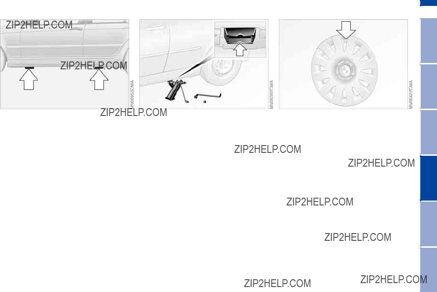
Changing a wheel
5.Position the jack at the jacking point closest to the flat tire with the jack base vertically below the jack- ing point. The entire surface of the head of the jack moves into the square recess of the jacking point ??? refer to the detail in the next illus- tration ??? when the jack is cranked
6.Jack the vehicle up until the wheel you are changing is raised from the ground
7.Unscrew the lug bolts and remove the wheel
8.Remove accumulations of mud or dirt from the mounting surfaces of the wheel and hub. Clean the lug bolts
9.Position the new wheel or the
10.Screw in the remaining lug bolts. Screw in all the bolts in a diagonal pattern
11.Lower the jack and remove it from beneath the vehicle
12.Tighten the lug bolts securely in a diagonal pattern
149
13.Wheels with full wheel covers*: place the wheel cover with the valve opening over the valve. Use both hands to press the cover securely onto the rim
14.Check and correct the tire inflation pressure at the earliest opportunity. Vehicles with Flat Tire Monitor: after mounting the spare tire or correcting the tire inflation pres- sure, reinitialize the system, refer to page 91.
Protect valve stems and valves from dirt using
 Repairs Maintenance Controls Overview
Index Data

Do not attempt to install the full wheel cover on the
spare tire, since this could damage the cover.<
The vehicle jack is designed for changing wheels only. Do not
attempt to raise another vehicle model with it or to raise any other type of load. To do so could cause accidents and personal injury.
To ensure continued safety, have the tightness of the torque bolts checked with a calibrated lug wrench ??? torque specification: 88.5 lb ft/120 Nm ??? at the earliest opportunity.<
When storing a wheel in the spare tire recess, take care to avoid bending the threaded rod.
If the original BMW
Replace the defective tire as soon as possible and have the new wheel/tire balanced.
Driving with the
Drive cautiously. Do not exceed a speed of 50 mph / 80 km/h.
Be aware that vehicle handling may be altered. Anticipate, e.g., reduced track- ing during braking, longer braking dis- tances, and changed steering charac- teristics when approaching limit conditions. These handling characteris- tics will be even more pronounced if winter tires are mounted.
Only one
Mount a wheel and tire of the original size at the earliest possible opportu- nity.<
Driving with a spare tire*
For certain wheel/tire combina- tions, the size of the spare tire will
differ from that of the remaining tires. The spare tire is fully functional at all loads and speeds. However, the spare tire should be replaced at the earliest possible opportunity in order to achieve the original operating conditions.<
Run Flat tires are labeled on the side- wall with a circular symbol containing the letters RSC. Run Flat tires consist of
When mounting or replacing sum- mer tires with winter tires, or vice versa, use Run Flat tires since no spare wheel is available in the event of a flat.
In this event, BMW recommends con- sulting your BMW center. Your BMW center has the information needed for working with Run Flat tires and is equipped with the necessary special tools.<
Run Flat tires*
Driving with a damaged tire
Depending on the cargo load, Run Flat tires allow you to continue driving at a maximum speed of 50 mph / 80 km/h. If there is a total loss of tire inflation pres- sure, 0 psi/0 kPa, or obvious tire dam- age, you can determine the distance you may continue driving based on the following values:
Maintenance
The battery is absolutely maintenance- free, that is, the original electrolyte will normally last for the service life of the battery under moderate climatic condi- tions.
Please consult your BMW center whenever you have any questions
concerning the battery.<
Controls Overview
Drive cautiously. Do not exceed a speed of 50 mph / 80 km/h. Be
aware that vehicle handling will be altered when there is a loss in inflation pressure. Anticipate, e.g., reduced tracking during braking, longer braking distances and changed steering char- acteristics.
For safety reasons, BMW recommends not having damaged Run Flat tires repaired. In this case, consult your BMW center.<
Charging the battery
When charging the battery in the vehi- cle, leave the engine off at all times. Connect the charge cables to the termi- nals in the engine compartment. For terminal locations, refer to
Disposal
Return used batteries to a recy- cling point or your BMW center.
Maintain the battery in an upright posi- tion for transport and storage. Secure the battery against tilting during trans- port.<
You will find the fuses and information on their respective allocation in the glove compartment behind a panel with two snap clips.
Do not attempt to repair a blown fuse or replace it with a fuse
having a different color or amperage rating. To do this could cause a fire in the vehicle resulting from a circuit over- load.<
Repairs Maintenance
Index Data

152 Receiving assistance
The BMW Group's Mobile Service offers you
The telephone numbers of the Mobile Service control center in your country are listed in the BMW Dealer Directory.
If your vehicle has the necessary equip- ment, you can contact the Mobile Ser- vice or issue an emergency call using buttons in the interior rearview mirror.
When an emergency call is initiated, a telephone connection is established with the general emergency call center.
In vehicles with activated BMW Assist function, a telephone connection is set up to the BMW Assist emergency call center. If the current location of your vehicle can be determined, this location is transmitted to the BMW Assist emer- gency call center.
Fold down the cover.
1Emergency call
2Mobile Service
Requirements for initiating an emer- gency call or contacting Mobile Service:
>The car phone is registered with a mobile network
>The emergency call system is opera- tional.
Initiating an emergency call*
Press button 1 for at least 2 seconds.
The indicator lamp above the buttons lights up. As soon as a telephone con- nection has been set up to the main emergency call center, the indicator lamp flashes.
If the indicator lamp is flashing but you cannot hear the emergency call center, you may still be heard by the emer- gency call center.
For technical reasons, the emer- gency call function cannot be
guaranteed in certain unfavorable con- ditions.<
If certain requirements are met, an emergency call is automatically initiated after a serious accident. The automatic emergency call will not be hindered by pressing the button.
Mobile Service*
To establish contact with the BMW Group's Mobile Service:
Press button 2 for at least 2 seconds.
The indicator lamp above the buttons lights up. As soon as a telephone con- nection has been set up with the Mobile Service, the indicator lamp flashes.
Depending on the country you are in, your vehicle's current location will also be transmitted if your vehicle is equipped with an activated BMW Assist function.

When your battery is discharged, you can use two jumper cables to start your vehicle with power from the battery in a second vehicle. You can also use the same method to help start another vehicle. Only use jumper cables with fully insulated handles on the terminal clamps.
Do not touch
Contact with components carrying high voltage can be harmful or fatal. Care- fully observe the following instructions to avoid personal injury and/or damage to one or both vehicles.<
Preparations
1.Check whether the battery of the support vehicle has 12 volts and approximately the same capacity ??? measured in Ah. This information is provided on the battery
2.Stop the engine of the support vehi- cle
3.Switch off all electrical components in both vehicles.
Make absolutely certain that there is no contact between the body-
work of the two vehicles, otherwise there is a short circuit hazard.<
Connecting the jumper cables
Always adhere to this sequence when connecting jumper cables;
failure to observe this procedure can lead to sparks at the battery terminals and pose an injury hazard.<
The auxiliary
1.Open the cover of the BMW auxiliary
153
2.Connect one terminal clamp of the plus/+ jumper cable to the positive terminal of the battery or to an auxil- iary
3.Connect the second terminal clamp of the plus/+ jumper cable to the positive terminal of the battery or to an auxiliary
4.Your BMW is equipped with a special nut ??? see arrow 2 ??? to serve as the ground or negative terminal.
Attach a terminal clamp of the minus/??? jumper cable to the negative terminal of the support vehicle's bat- tery or to a suitable ground on its engine or bodywork
5.Attach the second terminal clamp of the minus/??? jumper cable to the neg- ative terminal of the battery or to a suitable ground on the engine or bodywork of the vehicle to be started.
Starting the engine
1.Start the engine of the support vehi- cle and let it run for several minutes at a slightly elevated engine idle speed
 Repairs Maintenance Controls Overview
Index Data
Depending on the cause of the fault, have the battery checked and recharged by your BMW center.
Do not use spray starter fluids to start the engine.<
Towing with a commercial tow truck
>Use wheel lift or flat bed carrier
>Do not tow with
Never allow passengers to ride in a towed vehicle for any reason.
Never attach

Towing the vehicle
Towing the vehicle with the front Towing eyelet axle raised
Vehicles with automatic transmission:
1. Towing speed: maximum 45 mph /
70 km/h
2. Towing distance: maximum
90 miles/150 km.
Vehicles with sequential manual gear- box SMG:
While the ignition is on, move the selec- tor lever to position N, then turn off the ignition.
325xi: towing the vehicle with the front or rear axle raised
1.Place the transmission in Neutral
2.Switch off the engine
3.Towing speed:
max. 30 mph / 50 km/h
4.Towing distance: max. 90 miles/150 km.
Remove the rear driveshaft for longer towing distances with the
front axle lifted; remove the front drive- shaft for towing over longer distances with the rear axle lifted. Failure to com- ply with this will result in damage to the transfer box.<
156 Towing the vehicle
Rear:
Press out the cover panel with a screw- driver inserted in the recess at the top.
Avoid staggered towing and be careful that the towing strap is
taut before starting to drive the vehicle doing the towing.<
Use only a nylon towing strap to tow the vehicle, since the inherent resil- ience of this material helps protect both vehicles from sudden jerking move- ments.
The towed vehicle should always be the lighter of the two vehicles.
If this is not the case, it will not be pos- sible to control vehicle handling.<
Use only the towing eyelet sup- plied with the vehicle and screw it
in firmly until it stops. Use the towing eyelet for towing on paved roads only. If you do not follow these instructions, the towing eyelet could be torn out and vehicle damage could occur. Never attach
For instructions on
Never attempt to use your vehicle to push another car, since damage to the
157

158

159
Overview
Controls and features
Operation, maintenance
Owner service procedures
Technical data
Index
 Repairs Maintenance Controls Overview
Index Data

160 Engine data
325xi: power can be tested only on a suitable dynamometer.
Dimensions
161

162 Weights
Approved axle loads and approved gross vehicle weight must never be exceeded.

 Repairs Maintenance Controls Overview
Index Data

164

165
Overview
Controls and features
Operation, maintenance
Owner service procedures
Technical data
Index
 Repairs Maintenance Controls Overview
Index Data
Everything from A to Z

Everything from A to Z
167
CD changer, refer to the Owner's Manual for Radio/Onboard Computer
CD operation, refer to the Owner's Manual for Radio/Onboard Computer
Cellular phone 107 Center
lamp
bulb replacement 146 Central locking system 30
button 35 passenger compartment 35
Charge indicator lamp 18 Check Control 81
Check Gas Cap indicator lamp 19
Child safety locks 60 Child seats 57
system (LATCH) 59
Cigarette lighter 108 Cigarette lighter socket 108 Clean rear window 76 Cleaning chrome parts, refer
to the Caring for your vehi- cle brochure
 Repairs Maintenance Controls Overview
Index Data
Everything from A to Z

 Repairs Maintenance Controls Overview
Index Data
Everything from A to Z
 Repairs Maintenance Controls Overview
Index Data
Everything from A to Z
Making telephone calls, refer to the telephone Owner's Manual
Malfunction door lock 34
fuel filler door 24 Malfunction displays 81 Manual operation
door lock 34 driver's door 34 fuel filler door 24 glass sunroof 43 tailgate 36
Manual transmission 66 Master keys
with remote control 30 MC operation, refer to the
Owner's Manual for Radio/Onboard Computer
MD operation, refer to the Owner's Manual for Radio/Onboard Computer
Mechanical seats 45 Memory, refer to Seat and
mirror memory 50 Memory, refer to Vehicle
Memory, Key Memory 61 Microfilter
air conditioning 99 automatic climate control 104
Microphone, refer to Cellular phone 107
Mini disc operation, refer to the Owner's Manual for Radio/Onboard Computer
Mirror
automatic curb monitor 51 Mirrors 52
heated 52
memory, refer to Seat and mirror memory 50
Mobile Service 152 Modifications, technical,
refer to For your own safety 5
Multifunction steering wheel 22
turn signal indicator/head- lamp flasher 74 washer/wiper system 75
N
Navigation system, refer to the Owner's Manual for Radio/Onboard Computer
Neck restraints, refer to Head restraints 48
Nets 106
Nozzles, refer to Ventilation 96, 100
OBD interface socket 138 Odometer 79
Oil
additives, refer to Adding engine oil 133
capacity 163 dipstick 132 quality 133 viscosity 133
Oil change interval, refer to Service interval display 136
Oil change intervals, refer to the Service and Warranty Information Booklet for US models/Warranty and Ser- vice Guide Booklet for Canadian models
Oil consumption 132 Oil dipstick 132
Oil filter change 163 Oil level
checking 132 indicator lamp 18
Oil pressure indicator lamp 18
OIL SERVICE 81 Oil types 133
Old batteries, refer to Dis- posal 151
Onboard computer 83
Onboard computer, refer to the Owner's Manual for Onboard Computer
Onboard tool kit 142 Opening and closing
from inside 35 from outside 31 via door lock 34
via remote control 31 Outlets, ventilation 96, 100 Outside temperature dis-
play 83 changing unit of measure 83
P
Paintwork care, refer to the Caring for your vehicle brochure
Panic mode ??? trigger alarm 32
Park Distance Control (PDC) 85
Parking aid, refer to Park Distance Control (PDC) 85
Parking brake 65 indicator lamp 18
Parking lamps 93
bulb replacement 144 Parking lamps/Low
beams 93 Partition net 111

 Repairs Maintenance Controls Overview
Index Data
Everything from A to Z

 Repairs Maintenance Controls Overview
Index Data
Everything from A to Z
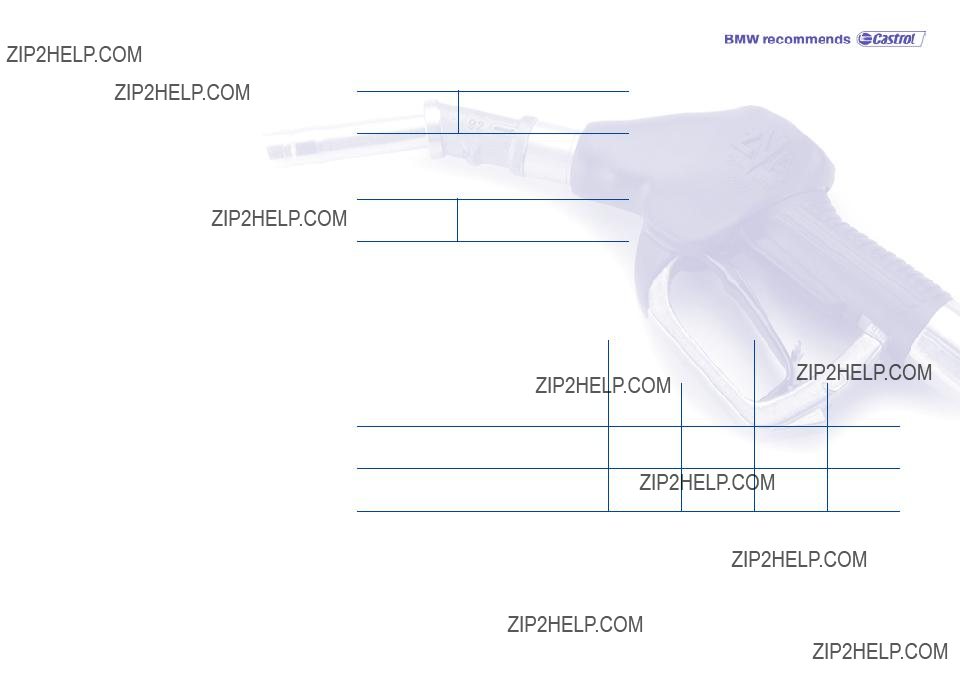
To ensure that you always have conve- nient access to all essential information when you stop for fuel, we recommend that you fill out the adjoining chart by entering the data that apply to your vehicle. Consult the index for individual specifications.
Refueling
Fuel
Designation
Please enter your preferred fuel here.
Engine oil
Quality
The oil volume between the two marks on the dipstick corresponds to approx. 1.1 US quarts/1 liter.
Tire inflation pressure
Up to 4 persons
5 persons or 4 plus luggage

01 41 0 157 605 ue