Model AA-RS20CS

Installation Manual

4 Channel Remote Car Starter

With Full Feature Alarm System

Installation Instructions

This Unit is Intended for Installation in Vehicles with

12 Volt Negative Ground Electrical Systems,

Gasoline Engines, and Automatic Transmissions Only.

Kit Contents:

AA-RS20CS Control Module

(2) - Three Button Anti Code Grabbing Transmitters

4 Channel Code Learning Receiver

On Board Extended Range Antenna

Six Tone Multi Tone Siren

(1)- Multi Pin Input/Output Harness

(1)- Six Pin Power Harness

(1)- Four Pin Auxiliary Output Harness

(1)- Two Pin LED Indicator

(1)- Two Pin Valet / Programming Switch

(1)- Two Pin Control Switch

(1)- Four Pin Shock Sensor Harness

(1)- Two Pin Door Lock Harness

(1)- Dual Stage Shock Sensor

(1)- Starter Inhibit Relay and Socket

(2)- 30 Amp In-line Fuse Holders With Fuses

(1)- Pin Switch Hardware Bag

(2)- Under Hood Caution Labels

(1)- Installation Manual

(1)- Operator's Manual

(1)- Limited Warranty

(2)- Window Decals

The AA-RS20CS Remote Start/Alarm System is designed to be used with Automatic Transmission Ve- hicles Only! The unit provides no output for glow plug pre-heat and may not be desirable for diesel vehicles. If the diesel engine has a instant fire, (no glow plug pre-heat system), a tach signal input, and an Automatic Transmission, this unit may be used. For diesel applications, consult your dealer for the type of ignition system in your particular vehicle.

INSTALLATION OF THE MAJOR COMPONENTS:

CONTROL MODULE:

Select a mounting location inside the passenger compartment (up behind the dashboard). The mounting location selected must be within 24" of the ignition switch wiring harness to allow connection of the 6 pin main wiring harness.

Be certain that the chosen location will not interfere with proper operation of the vehicle. Avoid mounting the module to or routing the wiring around the steering shaft/column, as the module or wiring may wrap around or block the steering wheel preventing proper control of the vehicle. Secure the module in the chosen location using cable ties or screws as necessary.

Do Not Mount The Module In The Engine Compartment, as it is not waterproof.

SIREN:

Select a location in the engine compartment that is not accessible from below the vehicle. The selected location must be clear of hot or moving parts within the engine compartment The siren must be pointed downward to prevent water retention and the flared end must be pointed away from and out of the engine compartment for maximum sound distribution. Before securing the siren, check behind your chosen location to assure that the mounting screws will not penetrate any factory wiring or fluid lines. Secure the siren mounting bracket using #8 self taping screws or by first using the mounting bracket as a template, scribe or mark the three bracket mounting holes. Drill the three marked holes using a 1/8" drill bit, than mount the siren using #8 sheet metal screws.

HOOD AND TRUNK PIN SWITCHES:

The pin switches included in this package are intended for protecting the hood and trunk areas of the vehicle. In all cases, the switch must be mounted to a grounded metal surface. When the pin switch is activated, (hood/trunk open), it will supply a ground to the input wire activating the alarm. In addition, the hood switch is required for the safety shut down of the remote start unit. If the vehicle is being worked on, this hood switch prevents the remote start activation even if the RF command to start is issued. This switch must be installed in all applications Failure to do so may result in personal injury or property damage. Mount the switches in the hood and trunk locations away from water drain paths. If necessary, the included brackets may be used to move the switch away from rain gutters or allow mounting to the firewall behind the hood seal. In both cases the switch must be set up to allow the hood or trunk door to depress the switch at least 1/4 inch when the hood or trunk is closed and fully extended when the hood or trunk is opened. For direct mounting, a 1/4 inch hole must be drilled. Carefully check behind the chosen location to insure the drill will not penetrate any existing factory wiring or fluid lines. Drill a 1/4" hole in the desired location and thread the pin switch into it using a 7/16" nut driver or deep well socket. If using the mounting bracket, first secure the bracket to the desired location and secure the pin switch in the pre- threaded mounting bracket hole.

DASH MOUNTED L.E.D.:

The small Red LED included in the kit will serve as a visual indicator of the alarm's status and provide a visual deterrent to a potential thief. The LED also provides important feed back information during the transmitter and feature program modes. The LED should be installed in the dash in an area highly visible so that it may be seen from the driver's seat as well as from outside the vehicle. Inspect behind the chosen location to insure that the drill will not penetrate any existing factory wiring or fluid lines. Carefully drill a 1/4" hole in the desired location and pass the connector end of the LED through the hole and toward the control module. Press the LED firmly into place until it is fully seated in the mounting hole.

2

THE RANGE EXTENDER ANTENNA:

The range extender antenna provided with this unit allows routing from below the dash board for maximum operating range. Choose a location above the belt line (dashboard) of the vehicle for best reception. Special considerations must be made for windshield glass as some newer vehicles utilize a metallic shielded window glass that will inhibit or restrict RF reception. In these vehicles, route the exposed, (non shielded) end toward a rear window location for best reception. Secure the exposed end with double stick tape or instant stick glue. After securing the exposed end of the antenna with the tape or glue, we advise also securing a section of the antenna cable to a fixed support. This will prevent the antenna from dropping down in case the double stick tape is exposed to extreme heat which may loosen it's gummed surface.

VALET/PROGRAM/MANUAL OVERRIDE SWITCH :

Select a mounting location that is easily accessible to the operator of the vehicle. It is not necessary to conceal the switch however concealment is recommended as it offers a higher level of security. The switch can be mounted to the lower dash panel in the drivers area. Inspect behind the chosen location to insure that adequate clearance is allowed for the body of the switch, and also that the drill will not penetrate any existing factory wiring or fluid lines. Drill a 1/4" hole in the desired location and mount the switch by passing it through the panel from the underside. Secure the switch using the nut, star washer, and on/off face plate. It is suggested that the switch be oriented to allow the on position to be up toward the driver and the off position to be down or away from the driver. Route the switch's connector toward the control module.

CONTROL SWITCH:

Select a mounting location known and accessible to the operator of the vehicle. A lower dash panel, kick panel, or glove box is desirable. Inspect behind the chosen location to insure that adequate clearance is allowed for the body of the switch, and also that the drill will not penetrate any existing factory wiring or fluid lines. Drill a 1/4" hole in the desired location and mount the switch by passing it through the panel from the underside. Secure the switch using the nut, star washer, and on/off face plate. It is suggested that the switch be oriented to allow the on position to be up toward the driver and the off position to be down or away from the driver. Route the switch's connector toward the control module. Place the RED rubber boot, included in the kit, over the switch handle to differentiate this switch from the valet/program switch.

SHOCK SENSOR:

Select a centrally located, solid mounting surface for the shock sensor that will allow consistent operation from all areas of the vehicle. The selected location must be within 18" of the control module to allow routing and connecting of the 4 pin harness. Secure the shock sensor to the chosen location using two #8 self taping sheet metal screws. The sensor can also be secured to an existing dash brace using cable tie straps. Whichever mounting method is used be sure to allow access to the sensitivity adjustment poten- tiometer for use later in the installation.

STARTER INHIBIT RELAY:

Select a mounting location within 12" of the ignition switch's low current start solenoid wire. Secure the relay to an existing harness in the chosen location using a cable tie around the relay's wiring harness. Caution! Do not wire tie the metal bracket to an existing wiring harness as vibration may cause chaffing

and shorting damaging the factory wiring. If an existing harness is not available then secure the relay's metal mounting tab to an under dash metal brace with a #8 self taping sheet metal screw. Wire the relay as per the diagram found later in this manual.

The AA-RS20CS is to be used in vehicles with AUTOMATIC TRANSMISSIONS only! Although this combination Alarm/Remote Start unit is a sophisticated system with many advanced features, IT MUST NOT be installed into a vehicle with a manual operated transmission. Doing so may result in serious personal injury and property damage.

IMPORTANT!

DO NOT PLUG THE SIX PIN MAIN POWER HARNESS OR THE MULTI PIN INPUT / OUTPUT HARNESS

INTO THE CONTROL MODULE UNTIL ALL CONNECTIONS TO THE VEHICLE HAVE BEEN MADE.

AFTER SELECTING YOUR TARGET WIRES AS DEFINED BELOW, DISCONNECT THE NEGATIVE

BATTERY CABLE FROM THE VEHICLE BATTERY PRIOR TO MAKING ANY CONNECTIONS.

3

WIRING THE 6 PIN MAIN POWER HARNESS:

RED w/ WHITE Trace Wire: + 12 volts Battery 1 Source

Connect this wire to a + 12 VDC constant source found at the vehicle's ignition switch using the 30 Amp fuse and holder provided.

RED Wire: + 12 Volts Battery 2 Source

Connect this wire to a + 12 VDC constant source found at the vehicle's ignition switch using the 30 Amp fuse and holder provided, but NOT the same vehicle wire as used by the battery 1 source. Most vehicles have more than one battery source supplying power to the ignition switch. Separate feed wires must be used for the Red and Red/White wires. If your vehicle does not have two battery feed wires at the ignition switch then it is possible to connect both wires to the vehicle's battery.

IMPORTANT!

It is the responsibility of the installing technician to determine the load factor of the vehicles electrical circuits when the vehicle is running and to adequately fuse the two power wires based on that load. If the vehicle, running under load with the air conditioner, heater blower motor, and accessories exceed 24 Amps continuous, we recommend that two fuses be used in combination on each power wire as shown below. For additional information see Tech Update issued 9/30/96.

YELLOW Wire: Starter Output

Careful consideration for the connection of this wire must be made to prevent the vehicle from starting while in gear. Understanding the difference between a mechanical and an electrical Neutral Start Switch will allow you to properly identify the circuit and select the correct installation method. In addition you will realize why the connection of the safety wire is required for all mechanical switch configurations.

Failure to make this connection properly can result in personal injury and property damage.

In all installations it is the responsibility of the installing technician to test the remote start unit and assure that the vehicle cannot start via RF control in any gear selection other than park or neutral.

In both mechanical and electrical neutral start switch configurations, the connection of the Yellow wire will be made to the low current start solenoid wire of the ignition switch harness. This wire will have +12 volts when the ignition switch is turned to the start (crank) position only. This wire will have 0 volts in all other ignition switch positions.

NOTE: This wire must be connected to the vehicle side of the starter cut relay (when used). For the electrical neutral switch configuration, this connection must be made between the starter inhibit relay, (when used) and the neutral safety switch as shown in the following diagram.

Failure to connect this wire to the ignition switch side of the of the neutral safety switch can result in personal injury and property damage.

SEE NEUTRAL START SAFETY TEST FOR FURTHER DETAILS. BLUE Wire: Ignition 1 Output

Connect this wire to the ignition 1 wire from the ignition switch. This wire will show +12 volts when the ignition key is turned to the to the "ON" or "RUN" and the "START" or CRANK" positions, and will have 0 volts when the key is turned to the "OFF" and "ACCESSORY" positions.

4

YELLOW START WIRE DETAIL

GREEN Wire: Ignition 2 Output

Connect this wire to the ignition 2 wire from the ignition switch. This wire will show + 12 volts when the ignition key is turned to the "ON" or "RUN" position and is some cases the "START" or CRANK" position. This wire will show 0 volts when the key is turned to the "OFF" and "ACCESSORY" positions.

VIOLET Wire: Accessory Output

Connect this wire to the Accessory wire from the ignition switch. This wire will show + 12 volts when the ignition switch is turned to the "ACCESSORY" or "ON" and "RUN" positions, and will show 0 volts when the key is turned to the "OFF" and "START" or "CRANK" positions.

5

WIRING CONNECTIONS: Multi Pin Accessory Input/Output Harness

White w/ Red Trace Wire: Parking Light Flasher Feed

This wire is the common contact of the on board parking light flasher relay. If the vehicle you are working on has +12 volt switched parking lights, connect this wire to a fused + 12 volt source. (Max. 15 Amps) NOTE: If the vehicle's parking lights are ground switched, connect this wire to chassis ground.

White Wire: Parking Light Flasher Output

This wire is the normally open contact of the on board parking light flasher relay. Connect this wire to the vehicle parking light feed wire. See diagram below for details on wiring positive switched parking light circuits.

Parking Light Wiring Detail

White w/ Black Trace Wire: (+) Siren Output

This is the positive siren feed wire. Route this wire through a grommet in the firewall to the siren location. Connect the White w/ Black Trace wire to the Red wire of the Siren. Secure the Black wire of the Siren to a known chassis ground or solid clean metal surface.

Siren Wiring Detail

SIREN

l

BLACK

(-) TO VEHICLE'S CHASSIS GROUND

6

Purple Wire: (+) Door Trigger Input

If the vehicle's door courtesy light switches + 12 volts when the door is opened, (Most Fords and some Imports), you must connect this wire to the positive output from one of the vehicle's door pin switches. In most cases, the Purple wire will need to be connected to only one door switch no matter how many doors the vehicle has as most door lighting circuits are wired in parallel. See below for wiring details.

Positive Door Switch Wiring Detail

Dark Green Wire: (-) Instant Trigger Input

This is the instant on ground trigger input wire. This wire must be connected to the hood and trunk pin switches previously installed.

Note: This wire will be shunted when remote control channel 2 is accessed, (trunk release). This wire will remain shunted all the while there is ground present and for 5 seconds after the ground is removed. This allows the operator to open the trunk via the remote transmitter without having to first disarm the alarm system. See below for wiring detail.

Hood Pin Switch Detail

Light Blue Wire: Ignition 3 Output

This wire provides a 300mA ground output that becomes active 3 seconds before the Remote Start Unit initializes, and remains grounded while running plus an additional 4 seconds after the Remote Start Unit turns off. In all of the applications described below, a relay will be required.

The Light Blue wire can be used to accommodate the following situations:

A.Shock Sensor By Pass:

If there is a Non Plug in Shock Sensor used with the alarm system and it is not shunted during the Remote Start activation period, then vibration from the running vehicle can cause the alarm to trigger. In this case, connect the Light Blue Wire to terminal #86 of a external relay. Connect terminal# 85 of the relay to a fused + 12 volt battery source. Cut the shock sensor trigger wire and connect one end of the cut wire to terminal #30 and the other end of the cut wire to terminal #87a. Just before the Remote

7

Start unit is activated, the relay contacts will open, preventing the shock sensor's operation until the Remote Start unit shuts off.

B.Ignition 3 Output:

Some newer vehicles use a third ignition wire which is required to start and keep the vehicle's engine running. If this is the case, connect the Light Blue wire to terminal #86 of an external relay. Connect terminal # 30 & # 85 to a fused + 12 volt battery source rated for a minimum of 25 Amp. Connect terminal # 87 to the third ignition wire in the vehicle.

C.GM VATS Key Override:

If the vehicle has the General Motors VATS system installed, you will need to by-pass the system while the vehicle is operating under the control of the Remote Start Unit. To Do This;

1.Measure the resistance of the resistor pellet on the ignition key then select a resistor within 5% of the key's value from the resistor pack supplied.

2.Locate the pair of VATS wires in the vehicle, usually a pair of thin gauge wires running from the ignition switch to the VATS control module.

NOTE: These wires are typically White w/ Black trace and Violet w/ Yellow trace, however in later model Cadillacs, they are run through an orange sleeve, and are either both Black, both Yellow, or both White wires. Consult the factory service manual for additional information.

3.Connect the Light Blue Wire from the Remote Start Unit to terminal #86 of an external relay. Connect terminal #85 of the relay to a fused + 12 volt battery source.

4.Cut (#1) wire (as shown), and connect the ignition switch side of the cut wire to terminal #87a of the relay. Connect the other side of the (#1) wire to terminal #30.

5.Connect the previously selected resistor from terminal #87 to the second (#2) wire (as shown). NOTE: The above information and following diagram is for the GM VATS system only. For GM PASS

LOCK System you will require the Audiovox AS-PASS II Module.

Green w/ White trace Wire: Entry Illumination Ground Output

This wire provides a 30 second ground output (300 mA Max.) whenever the remote is used to disarm the alarm or to unlock the doors and provides a continuous pulsed output whenever the alarm is triggered. This wire should be connected to an external relay, and wired to the vehicles interior entry lighting whenever the optional Interior Illumination circuit is desired. See below for relay wiring details.

Grey w/ Black Trace Wire: Negative Inhibit Input

The Grey w/ Black Trace wire provides an instant shutdown for the Remote Start Control Module when- ever it is grounded. Connect the Grey w/ Black trace wire to the hood pin switch previously installed. This wire must be routed through a grommet in the firewall and connected to the hood pin switch. If the pin

General Motors VATS By-Pass Diagram

8

Entry Illumination Detail

switch is to be used with an alarm system, connect this wire using the diode assembly provided. IMPORTANT! This connection is a safety wire and must be connected as shown and tested as specified.

Failure to do so may result in personal injury or property damage. See detail of wiring in the following diagram. This wire may also be used if the vehicle brake light circuit switches ground to the brake lights. An isolation diode must be used for ground switched brake light circuits and must be connected to the output of the brake switch.

Orange Wire: Ground When Armed Output

This wire provides a 300 mA ground output when the alarm circuit is armed to control the starter inhibit relay. Connect the Orange wire to terminal #86 (orange wire) of the relay provided. Connect terminal #85 (red wire) of the relay to an ignition wire in the vehicle that is +12 volts when the ignition switch is turned to the on and start positions and off when the key is off. Locate and cut the low current start solenoid wire found at the vehicles ignition switch harness. This wire will have + 12 volts when the

Grey w/ Black Trace Negative Inhibit Safety Shut Down Detail

ignition key is moved to the start (crank) position and will have 0 volts in all other key positions. Connect one side of the cut wire to terminal #87a ( Black wire) of the relay. Connect the other side of the cut wire to terminal #30 (White/Black wire) of the relay. See below for detail of wiring, also see Yellow Start wire detail for connection to vehicle considerations.

Brown w/ Black Trace Wire: Positive Inhibit Input

The Brown w/ Black Trace wire provides an instant shutdown for the Remote Start Control module whenever it gets + 12 volts. If the Brake lights switch in the vehicle switches + 12 volts to the brake light circuit, connect the Brown w/ Black trace wire to the output side of the brake switch. This will allow the

9

Remote Start to shut down if an attempt is made to operate the vehicle without the key while running under the control of the Remote Start. In most vehicles, in order to shift into gear, the brake pedal must be depressed. The brake input will in turn cause the remote start unit to shut off. See detail in the following diagram for wiring the brake light circuit.

Starter Inhibit Wiring Detail

Black Wire: Chassis Ground Source

Connect the Black wire to a known vehicle ground source or to a solid clean metal part of the chassis. Be certain to remove any paint or grease and secure this wire with a self taping screw and ring terminal.

Green w/ Orange Trace Wire: Tachometer Input Signal

This wire will continually monitor the engine tach rate while the unit is under power of the Remote Start module. This wire will be routed to the vehicle ECM tach input or through the firewall into the engine compartment and connect to the negative side of the ignition coil. This Remote Start unit learns the tach rate of the vehicle and in most cases will operate properly from one multi coil pack regardless of the number of cylinders. If the vehicle has a single coil unit for each cylinder, it may be necessary to connect this wire to more than one cylinder for proper tach reference. See multi coil wiring detail shown later in this manual for additional information.

Brake Switch Positive Shutdown Detail

10

Brown Wire: Negative Door Trigger

If the vehicle's door courtesy light switches ground when the door is opened, (Most GMs and Imports), you must connect this wire to the negative output from one of the vehicle's door pin switches. In most

Chassis Ground Connection Detail

cases the Brown wire will need to be connected to only one door switch no matter how many doors the vehicle has as most door lighting circuits are wired in parallel. See below for wiring detail.

Dark Blue Wire: Delayed 300mA Pulsed Channel 2 Output

The Dark Blue wire supplies a 300mA ground pulsed output whenever channel two of the receiver is accessed. Pressing the pre-programmed transmitter button for three seconds will access channel two. This is a low current output and must be connected to a relay to supply power to the trunk release or the circuit you wish to control. Connect the Dark Blue wire to terminal # 86 of a VF45F11 P&B relay or equivalent. Connect terminal # 85 of the relay to a fused + 12 volt source. Connect the common,

Tachometer Input Wiring Detail

normally open, and normally closed contacts of the relay to perform the selected function of channel 2. See below for relay wiring detail.

Green w/ Black Trace Wire: 300mA Latched Channel 3 Output

The Green w/ Black Trace wire supplies a 300 mA switched output whenever channel three of the receiver is accessed. Pressing the pre-programmed transmitter button(s) will access channel three

Negative Door Switch Wiring Detail

11

and will remain active for as long as the transmitter button(s) is held. This is a low current output and must be connected to a relay to supply power to the device you intend to control. Connect Green w/ Black Trace wire to terminal #86 of a VF45F11 P&B relay or equivalent. Connect terminal #85 of the relay to a fused + 12 volt source. Connect the common, normally open, and normally closed contacts of the relay to perform the selected function of the channel 3 output.

WIRING THE 4 PIN AUXILIARY OUTPUT HARNESS

The auxiliary 4 pin connector provides low current outputs to control various functions in the vehicle during different stages of the Remote Start unit's operation. Understanding these outputs and the time

Channel 2 Relay Wiring Detail

in which they occur will allow you to determine if they are needed for the particular vehicle you are working on as well as how to use them.

Black w Blue Trace Wire: Pulsed Ground Output Before Start

The Black w/ Blue Trace wire will provide a 300 mA pulsed ground output 3 seconds before the remote start unit activates. Typical use for this output would be to disarm a factory theft deterrent system to prevent false triggering of the factory alarm when the remote start unit engages.

Black w/ Light Green Trace Wire: Pulsed Ground Output After Start

The Black w/ Light Green Trace wire will provide a 300ma pulsed ground output after the vehicle is started under control of the remote start unit. Typically this wire will be used to re-lock the vehicle doors if the doors unlock automatically when the factory anti-theft system is disarmed.

Black w/ Red Trace Wire: Pulsed Ground Output After Shutdown

The Black w/ Red Trace wire will provide a 300 mA pulsed ground output after the remote start unit shuts down. This output will occur regardless of whether the circuit times out or is manually terminated. Typically this output will be used to re-lock the vehicle doors if the doors unlock automatically when the ignition circuit transitions to off.

Black w/ Yellow Trace Wire: Ground Output During Start (Crank)

The Black w/ Yellow Trace wire will provide a 300 mA ground output while the starter output of the remote start unit is active. This output can be used to activate the Crank Low/Bulb Test wire found in some GM vehicles. This wire is also referred to as the ECM wake up wire in some Chrysler vehicles. NOTE: The outputs above are low current outputs and must be used with a relay if the circuit's

requirement is more than 300 mA.

2 Pin Control Switch: (Red Connector)

The Black & Black w/White Trace wires loaded in the two pin red connector enable the operation of the Remote Start unit. When the Black w/ White Trace wire is grounded, the remote start unit is operable. When this wire is open from ground, the remote start is disabled. Route the twin lead Black and Black w/White Trace wires from the control switch to the remote start unit and plug red two pin connec- tor into the mating red two pin connector shell of the control module.

4 Pin Shock Sensor: (White Connector)

The Red (+12 volt), Black (ground), Blue (pre-detect) and Green (full trigger when armed) wires loaded into the white connector shell are the inputs/outputs of the shock sensor. Route the 4 wire harness from the shock sensor to the remote start control unit and plug the 4 pin white connector into the mating 4 pin connector shell of the control module. Note: While operating under the control of the remote start unit

12

the shock sensor will be shunted (by-passed). Once the remote start shuts down, the shock sensor will be re-enabled.

2 Pin LED Harness: (White Connector)

The Red & Blue wires loaded into the two pin mini white connector control the anode and cathode of the dash mounted LED. Route the twin lead Red and Blue wires from the LED to the remote start control unit and plug the two pin connector into the mating white mini connector shell of the control module.

2 Pin Valet/Program Switch: (Blue Connector)

The Black & Grey twin lead wires loaded in the two pin blue connector are the ground supply and program/valet input of the Remote Start unit. When the Grey wire is grounded, under certain conditions, the unit will enter the valet mode. When the Grey wire is sequentially grounded under other conditions, the unit will enter the various program modes. Route the twin lead Black and Grey wires from the valet/ Program switch to the remote start unit and plug the two pin connector into the mating blue connector shell of the control module. Refer to the remote programming, feature programming and function pro- gramming shown later in this installation guide for operation of the valet/program switch.

2 Pin Door Lock/Unlock Harness: (White Connector)

The Red & Green Door Lock/Unlock output wires provide either a pulsed ground or pulsed + 12 volts to control the vehicle door lock / unlock circuits. The output of these wires has a maximum switching capability of 300mA. Many vehicles today have factory door lock relays which can be connected directly to these outputs, however always confirm that the factory relays in your particular vehicle do not exceed the rated 300mA output of the units door lock/unlock circuit. Plug the two pin connector of the door lock/ unlock harness into the mating connector shell of the control module. Determine the door lock circuit of the vehicle you are working on and wire according to the diagrams shown.

3 Wire Ground Switched Door Lock Circuits:

In this application, the Red wire of the two pin harness provides a ground pulse during the arming sequence, or pulsed ground lock output. Connect the Red wire to the low current ground signal wire from the factory door lock switch to the factory door lock relay.

The Green wire of the two pin harness provides a ground pulse during the disarming sequence, or pulsed ground unlock output. Connect the Green wire to the low current ground signal wire from the factory door unlock switch to the factory door unlock relay. See Below For Wiring Detail.

3 Wire Positive Switched Door Locks:

In this application, the Red wire of the two pin harness provides a + 12 volt pulse during the disarming sequence, or pulsed 12 volt unlock output. Connect the Red wire to the low current 12 volt signal wire from the factory door unlock switch to the factory door unlock relay.

The Green wire of the two pin harness provides a + 12 volt pulse during the arming sequence, or pulsed 12 volt lock output. Connect the Green wire to the low current 12 volt signal wire from the factory door lock switch to the factory door lock relay. See Below For Wiring Detail.

Note: For connection to Four Wire Polarity Reversal, 5 Wire Alternating 12 Volts, And All Other Door Lock Circuits the Audiovox AS-9159 Door Lock Interface, (or equivalent 30 A automotive relays)

3 Wire Ground Switched Door Lock/Unlock Wiring Detail

13

must be used. Refer to the Audiovox Door Lock Wiring Supplement for proper wiring of these circuits.

ALARM SELECTABLE FEATURES

NOTE: The Alarm Selectable Features and Remote Start Selectable Features programming steps following are based on transmitter button 1 being programmed for channel 1 and transmitter button 2 being programmed for channel 2.

3 Wire Positive Switched Door Lock/Unlock Wiring Detail

To Program The Alarm's Selectable Features:

NOTE: Once you've entered the program mode DO NOT allow more than 15 seconds to pass between steps, or the programming mode will be terminated.

14

TIMED START PROGRAM:

The Remote Start unit has the ability to start the vehicle automatically at timed intervals. This feature is useful in extremely cold climates where starting the engine is the only means to keep the battery charged and fluids warm. The operator has the option to have the unit start every 2 or 4 hours for a maximum of 48 hours. Factory pre-set is to start at 4 hour intervals. To select 2 or 4 hour automatic start timer:

1.Start with the Enable switch (Red Handle) in the "On" Position.

2.Turn the ignition on then off.

3.Within 10 seconds of the key turning off, cycle the enable switch Off, On, Off, On ( 2 times) to select a 2 hour timed start interval. Cycle the enable switch Off, On, Off, On, Off, On, Off, On (4 times) to select a 4 hour timed start interval. The lights will flash and the siren will chirp 2X or 4X dependant upon 2 or 4 hour interval setting.

NOTE: Once selected, 2 or 4, this timer interval will remain in memory until it is manually changed. To change, the above sequence will have to be followed.

TIMED START OPERATION:

To begin the start timer, within 10 seconds of turning off the ignition switch, activate the RF command to start 2 times. (Press button two 4 times). The lights will flash and the siren will chirp 4 times. Indicating timed interval mode has been initiated. The vehicle will automatically start every 2 or 4 hours as programmed. To cancel the timed start mode start the vehicle either by RF or by the ignition key.

15

REMOTE START SELECTABLE FEATURES

RF Programmable Features:

To Program The Remote Start Selectable Features:

1.Start with the valet/program switch in the "Off" position.

2.Turn the ignition key to the On position.

3.Flip the valet/program switch On, Off, On, Off, On, then Off.

4.Immediately turn the ignition key Off then press transmitter button 2 for 1 second.

5.Immediately turn the ignition key back On.

6.Flip the valet/program switch On, Off, On, then Off. The siren will emit 2 short and 1 long chirp verifying you are in the feature program mode.

7.Use button 1 on the transmitter to advance to the feature you want to change. EXAMPLE- If you need to change selectable feature 3, press and release button 1 three times in succession. The parking lights will flash, and the siren will chirp 3 times confirming that selected feature 3 can be changed.

8.Use button 2 on the transmitter to change the selection of the programmable feature. If you are not sure what the setting for any feature is, press button 1, one time, the parking lights will flash once or

twice indicating the features setting.

NOTE: Once you've entered the program mode DO NOT allow more than 15 seconds to pass between steps, or the programming mode will be terminated.

Programming Tach Rate:

The AA-RS20CS will learn the tach rate of the vehicle. To learn tach.

1.Start with the programming switch in the Off position.

2.Turn the ignition key to the On position.

3.Flip the valet/program switch On, Off, On, Off, On, then Off.

4.Immediately turn the ignition key Off.

5.Flip the valet/program switch On, then start the vehicle using the key.

6.When the unit senses the tach signal, the parking lights will begin to flash.

7.Flip the valet/program switch Off, The parking lights will turn on for three seconds to indicate that the learned tach signal is stored and the unit is out of the tach learn mode.

NOTE: If the unit fails to learn tach rate due to an improper tachometer connection or a poor tach source, the unit will go into a fail-safe mode. While in this mode, the remote start transmitter will not function and the program switch will stop responding. This will be indicated by the LED turning on and off with each operation of the program switch. To correct this situation, locate and connect the Green/Orange wire to the proper tach signal, disconnect the power wire to the control module, repower the circuit, re-enter and learn the proper tach signal.

Diagnostics:

Enter selectable feature #7 and turn on as described above.

NOTE: Diagnostic mode is a temporary mode. Once you have accessed the diagnostic mode, the unit

16

will pause for two seconds then begin to flash the last stored shut down code. This code will be displayed three times in succession, then the unit will automatically exit the diagnostic on mode.

The parking lights will flash a number of times indicating the reason for the last remote start shutdown. The light flash indications are as follows:

Multi Coil Pack Adaptor: (Optional)

The multi coil pack adaptor is designed for use with vehicles having multiple ignition coils where a single point tach signal is unavailable.

To use the adaptor, the Green/Black wires must connect to the negative side of the ignition coil(s).

1.For vehicles utilizing independent coils per cylinder, connect the three Green/Black leads to alternate coils. To achieve optimum performance the coil signals must be evenly distributed. This is accom- plished by first mapping out the firing order of the engine in groups of as indicated below. Draw a circle around any of the columns. The Green/Black wires should be connected to the negative (-) terminal of the respective cylinder number which appears in any of the circles.

2.For vehicles utilizing 2 cylinder firing per coil pack, connect Green/Black to the tach side of each coil pack. For 8 cylinder, four coil systems, connect to any of the three coils.

3.Connect the Yellow wire to a +12 volt ignition 1 source. This wire will have +12 volts with the ignition in the on and start position and have 0 volts with the ignition in the off position.

4.Connect the Green wire to the (Green) or (Orange/Green) tach input of the Audiovox remote start unit.

17

TESTING YOUR INSTALLATION:

WARNING !! The following procedure must be performed after the installation of an Audiovox Remote Start Device. It is the responsibility of the installing technician to complete these tests. Failure to test the unit in the following manner may result in personal injury, property damage, or both.

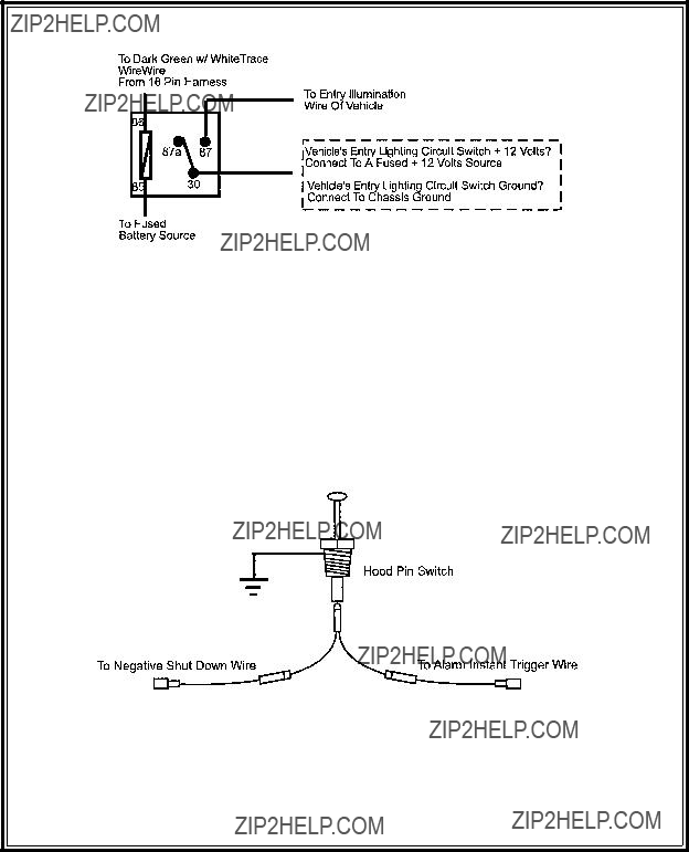
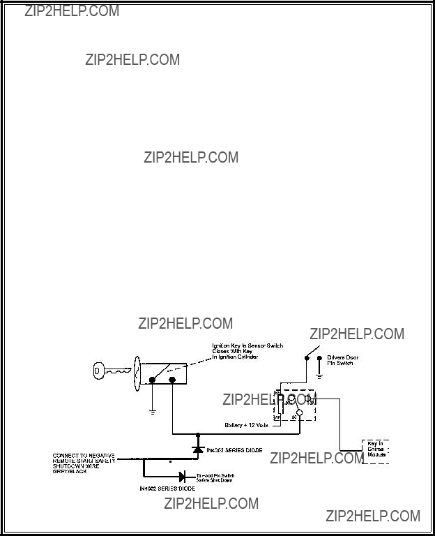
HOOD PIN SAFETY SHUT DOWN:

The intention of the hood pin safety shut down is to prevent the Remote Start unit from being activated while a mechanic or vehicle owner is performing normal routine vehicle maintenance.

To test the integrity of this circuit:

1.With the drivers window in the down position, start the vehicle using the RF transmitter.

2.Reach inside the car and pull the hood release.

3.Raise the hood and confirm that the remote start unit shuts down.

If the unit fails this test, recheck your pin switch connection to the Gray/Black wire of the Audiovox Remote Start Unit.

DO NOT RELEASE THIS VEHICLE TO THE CONSUMER UNTIL YOU CONFIRM THE

OPERATION OF THE HOOD PIN SAFETY SHUT DOWN FEATURE.

MANUAL SHUT DOWN / ENABLE CIRCUIT:

The intent of the manual shut down / enable circuit is to allow the vehicle operator to prevent operation of the Remote Start Unit regardless of the RF transmitter operation.

To test the integrity of the manual shut down / enable circuit:

1.Place the control switch in the on (Closed To Ground) position.

2.Start the vehicle using the RF transmitter.

3.The vehicle should start and run under the control of the remote start unit.

4.Move the switch to the off (Open From Ground) position, the vehicle should shut off.

If the unit fails this test, recheck your enable switch connection to the Ground and the Black/White wire of the Audiovox Remote Start Unit. If you have a plug in enable switch, check that the two pin connector is firmly seated in the mating connector on the control module.

DO NOT RELEASE THIS VEHICLE TO THE CONSUMER UNTIL YOU CONFIRM THE

OPERATION OF THE MANUAL SHUT DOWN / ENABLE FEATURE.

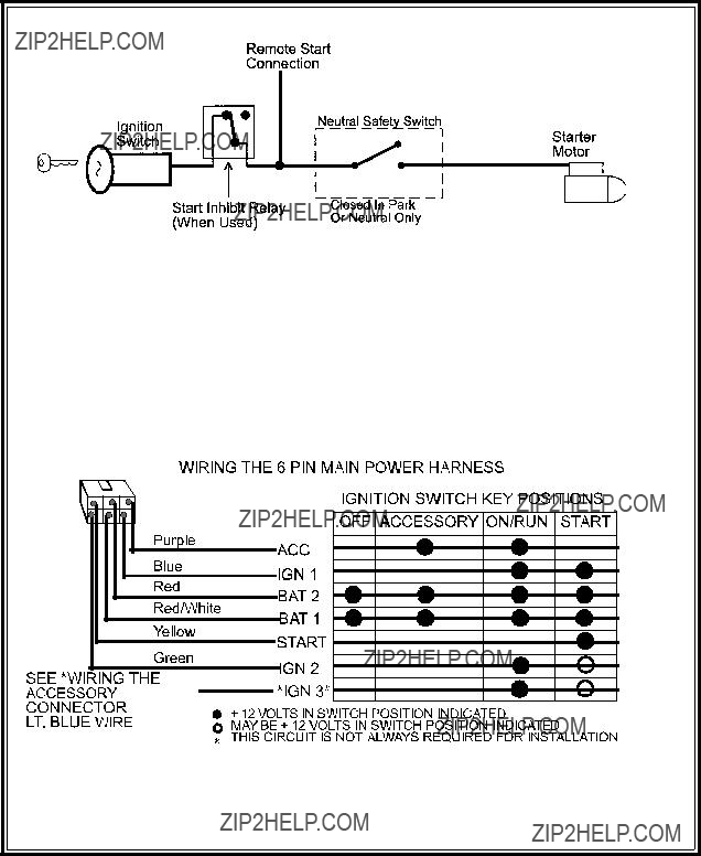
NEUTRAL START SAFETY TEST:

The intent of the neutral start switch is to prevent the vehicle from starting while the gear selector is in any position other than Park, or Neutral. When installing a Remote Start Device, it is imperative that the Yellow Starter wire be connected to the ignition switch side of the Neutral Start Switch. Consideration for the placement of a starter inhibit relay is important as well, and should be connected to the ignition switch side of the Yellow Start Wire.

To test the integrity of the Neutral Start Safety Circuit:

1.Set the vehicle parking brake.

2.Block the drive wheels to prevent vehicle movement.

3.Temporarily disconnect the Brown/Black positive shut down wire from the vehicle's brake switch.

4.Sitting in the vehicle, start the engine using the vehicle's ignition key.

5.Step on the brake pedal and shift the gear selector into reverse.

6.Allow the transmission to shift. When you feel the engine pull, do not move the gear selector just turn the ignition switch off. DO NOT attempt to remove the key.

7.Keeping the brake pedal depressed, activate the RF transmitter in an attempt to start the vehicle. The car should not start.

18

8.Repeat the above test this time move the gear selector to the drive position. If the unit attempts to start, failing this test, recheck your Yellow Wire's connection. This wire must be connected to the ignition switch side of the Neutral Start Switch. If the vehicle you are working on does not have an Electrical Neutral Safety Switch, it will be necessary to re-configure the Remote Starts Wiring to accommodate this vehicle. The information concerning the Mechanical Neutral Safety Switch provided below will help you to determine if the vehicle you are working on has this type of safety switch and

will provide alternate wiring methods to accommodate this situation.

CAUTION!

REMEMBER TO RECONNECT THE BROWN/BLACK WIRE TEMPORARILY

DISCONNECTED IN STEP 3

DO NOT RELEASE THIS VEHICLE TO THE CONSUMER UNTIL YOU CONFIRM THE OPERATION

OF THE NEUTRAL SAFETY START FEATURE.

MECHANICAL NEUTRAL SAFETY SWITCH CONSIDERATIONS:

Mechanical neutral safety switch configurations differ slightly in that they do not offer the same level of safety when installing a remote start device. Often when the ignition switch is turned off while the gear selector is in any position other than park or neutral, the mechanical function will not allow the key to be turned to the start position or be removed from the ignition cylinder. This configuration prevents me- chanical operation while the vehicle is in gear but offers no consideration for electrical operation. Be- cause of this potential problem, this installation requires the additional connection of a safety wire from the remote start device to the vehicle Park/Neutral ECM Input or the vehicle key in sensor. This connection will prevent remote start operation if the key is left in the ignition switch regardless of the gear selectors position.

PARK / NEUTRAL ECM INPUT:

The Park / Neutral ECM input is the preferred method of installation. This not only maintains the integrity of the factory circuit, it is also the easiest to install, providing the vehicle you are working on has this ECM input.

The installation required for this application (shown below), indicates the slight re-configuration of the control switch wiring and the addition of a 4000 series diode. Shown is a typical GM Park/Neutral ECM

19

input circuit. To connect the Audiovox remote start unit to the GM Park / Neutral ECM input:

1.Locate the Orange / Black reference wire in the" C2" connector found at the ECM in GM B Body vehicles or, locate the equivalent reference wire in the vehicle you are installing the Audiovox Remote Start Unit in.

2.Connect the Cathode, (Striped) end, of a 4000 series diode to this reference wire.

3.Connect the Anode, (Non Striped) end, of the diode to one side of the Remote Starts enable switch.

4.Connect the other side of the enable switch to the Black/White enable input wire of the Remote Start unit.

The reference diagram below shows a typical GM B Body ECM reference wire and how it is to be connected to the Remote Start Unit.

KEY IN SENSOR CIRCUITS:

If the vehicle you are working on does not have or you cannot locate the ECM reference wire, there are two alternatives available. Although not preferred, the vehicle Key In Sensor may be re-configured to allow a margin of safety and will prevent the vehicle with a Mechanical Neutral Start Switch from starting in gear.

AUDIOVOX ADVISES THAT YOU MAINTAIN THE FACTORY CIRCUIT WHENEVER POSSIBLE. The following two circuits may be used only if the above circuit is not available.

NOTE: When completing an installation using either of the following key in sensor circuits, if the operator inserts the ignition key while the vehicle is running under the control of the Remote Start, the vehicle will shut down. This must be explained to the operator as it is in contrast to the normal operation of a vehicle utilizing an electrical neutral start switch and is inconsistent with the operators manual.

Additional information concerning Key In Sensor methods 1 & 2 are listed below and should be reviewed before considering either alternative.

Method 1 will allow the safety required for the remote start unit and prevent the vehicle from starting while in any gear other than Park or Neutral while the key is in the ignition cylinder however, if the key is left in the ignition switch and the door is left opened, the added relay will be energized causing a 150mA drain on the battery.

METHOD 1

20

Method 2 will allow the safety required for the remote start unit and prevent the vehicle from starting while in any gear other than Park or Neutral while the key is in the ignition cylinder however, the original factory key in chime module will not alert the owner that the key has been left in the ignition switch. In addition, this may also effect other warning tones such as the light on reminder.

METHOD 2

These situations should be carefully considered before altering the vehicle's wiring and must be fully explained to the consumer.

To connect to the key in sensor as shown in method 1:

A.Locate the control wire that connects the drivers door pin switch to the key in sensor switch.

B.Cut this wire and connect the ignition cylinder side to chassis ground.

C.Locate the key in sensor switch wire that connects the chime module to the ignition cylinder .

D.Cut this wire and connect the ignition cylinder side to terminal 30 of a P&B VF45F11 or equivalent relay.

E.Connect the cathode (striped) side of a 4002 series diode to this same wire, and connect the (non striped) side to the negative shut down safety wire (Gray / Black) of the Audiovox Remote Start Unit.

F.Connect terminal 86 of the relay to a fused +12 volt constant battery source.

G.Connect terminal 87 of the relay to the Chime Module side of the previously cut wire in step D.

H.Connect terminal 85 of the relay to the Drivers Door side of the pin switch wire previously cut in step B. NOTE: A second 4002 series diode may be required to maintain the integrity of the hood open, shut down circuit. If this is the case, it must be installed as shown in the diagram above. The anode (Non Striped) side must be connected to the Gray/Black wire of the Remote Start Unit. The cathode (Striped) side must be connected to the hood pin switch. If the hood pin switch is also used for an alarm trigger input, be certain to use the dual diode assembly packaged with the

Audiovox Remote Start Unit as shown in this installation guide. (Page 9) To connect to the key in sensor circuit as shown for method 2:

A.Locate the control wire that connects the drivers door pin switch to the key in sensor switch.

B.Cut this wire and connect the ignition cylinder side to chassis ground.

C.Locate the key in sensor switch wire that connects the chime module to the ignition cylinder .

D.Cut this wire and connect the ignition cylinder side to the Remote Start Negative Safety Shut down Wire Gray/Black, using a 4002 series diode as shown above.

NOTE: A second 4002 series diode may be required to maintain the integrity of the hood open, shut down circuit. If this is the case, it must be installed as shown in the diagram above. The anode (Non Striped) side must be connected to the Gray/Black wire of the Remote Start Unit. The cathode (Striped) side must be connected to the hood pin switch. If the hood pin switch is also

21

used for an alarm trigger input, be certain to use the dual diode assembly packaged with the Audiovox Remote Start Unit as shown in this installation guide. (Page 9)

AFTER THE CONNECTION OF THE NEUTRAL START SAFETY WIRE AS INDICATED IN ANY OF

THE PREVIOUS ALTERNATE CONFIGURATIONS, THIS CIRCUIT MUST BE TESTED FOR OPERATION. Retest by following the steps outlined in the NEUTRAL START SAFETY TEST shown in this manual.

COMPLETING THE INSTALLATION:

After you have confirmed the operation of the Audiovox Remote Start unit and tested all the safety features of the system:

1.If you have not done so already, place the red rubber handle cover over the handle of the control switch for ease of identification. This will allow your customer to distinguish the Remote Start control switch from the program switch.

2.Mount the control module up and behind the dash securing it in place with cable ties or screws. Be certain that the chosen mounting location will not inhibit any of the controls of the vehicle.

3.Securely harness and tie all wiring up and away from all hot and moving parts that they may come in contact with under the dash board or in the engine compartment areas.

CAUTION: Particularly avoid the area around the steering shaft and column, as wires can wrap around these mechanisms and impair the safe operation of the vehicle.

4.Apply the Caution Labels supplied with this kit to a conspicuous area in the engine compartment. Make sure to clean the surface before affixing the label.

5.Check the vehicle's wipers, lights, horn, etc.... to insure proper operation.

6.Replace all panels that were removed during installation, and retest the system.

7.Explain all activated features and safety systems associated with Remote Start Unit installed to the customer.

22