OWNER???S MANUAL
DPF908
Digital Photo Frame
OWNER???S MANUAL
DPF908
Digital Photo Frame
A.Introduction
Thank you for selecting the DPF908 Digital Photo Frame. The main features include a 9" Screen (16:9 Aspect Ratio) Liquid Crystal Dis- play (LCD) monitor. The unit applies the latest state of the art elec- tronics and is designed for use with SD/MMC/MS/CF/xD memory cards and USB memory devices. The unit is constructed to provide years of reliable,
B.Cautions and Warnings
1. Placement
To prevent fire or electric shock, do not expose the DPF to rain or moisture. To prevent it from falling do not place the DPF on an unstable cart, stand, tripod, bracket or table. Keep the unit away from strong magnets, heat sources, direct sunlight, and exces- sive dust.
2. Installation
Ensure that the DPF is used in accordance with the instructions and illustrations provided in this manual.
3. Objects and Liquid
Do not push objects of any kind into the unit through openings; do not spill or spray liquid of any kind on or in the DPF (this may result in a fire or electric shock). Do not place anything heavy on the DPF. To ensure proper ventilation and proper operation, never cover or block the slots and openings with a cloth or other material.
4. Disassembly
Do not attempt to disassemble the DPF. There is a risk of electric shock. Contact qualified service personnel if your system is in need of repair.
5.Cleaning Unit
When cleaning, make sure the DPF is unplugged from the power source. Do not use liquid cleaners or aerosol cleaners. Use a cloth lightly dampened with water for cleaning the exterior of the DPF only.
2
C. Contents
1.1 x 9??? Digital Picture Frame w/Battery (CR2025)
2.1 x AC to DC Adaptor
3.1 x Remote Control w/Battery (CR2025)
4.3 x Interchangeable Frame (Black/White/Wood Grain)
5.1 x Instruction Manual
D. Positioning Your Frame
Pull out the stand to place the frame. Rotate the stand to position the frame vertically or horizontally. Adjust the stand???s length to obtain the desired vertical or horizontal viewing angle.
3
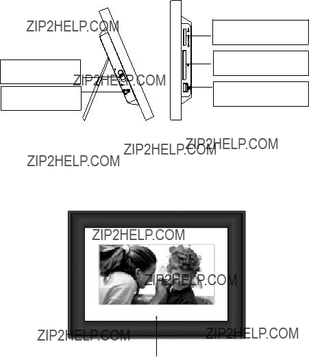
E. Unit View
Left and Right Side
Power On/Off Switch
DC 9V
Plug the AC adaptor
SD/MMC/MS Slot
Insert the SD/MMC/MS card
CF Slot
Insert the CF card
USB Slot
Insert a USB memory device
Note: The USB slot can not be connected to a PC for transferring pictures from the PC to the DPF.
Front Side
IR Sensor
4
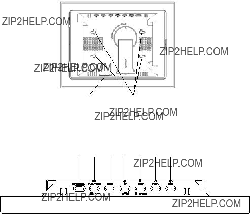
Back Side
1)Brightness: Press to adjust the Brightness.
2)Play/Pause/Mode: Press to PLAY/PAUSE or select an option.
3)Menu: Press to access the main menu.
4)Up/Copy/Delete: Press to navigate, copy or delete a photo.
5)Down/Rotate: Press to navigate or rotate a photo.
6)Prev. : Press to navigate or view the previous photo.
7)Next: Press to navigate or view the next photo.
5

F. Remote Control
MENU
6
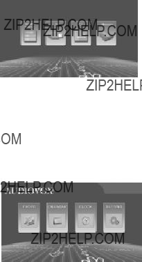
G.Viewing Photos
1.Attach the AC / DC adapter to the DC power jack and plug the adapter into an AC outlet.
2.Place the unit???s Power switch to the ON position and wait for the to display the Main Menu.
3.Insert the desired Media into the unit???s SD/MMC/MS USB or CF slots provided.
4.Using the LEFT / RIGHT arrow keys position the high- light over the PHOTO icon and press the MENU button.
5. Select the desired media by using the unit???s LEFT / RIGHT arrow keys to position the highlight. Once the desired media is highlighted press the PAUSE / PLAY / MODE button to confirm your selection.
Note: Only the media installed in the unit will be allowed to be se- lected.
6.With the Main Menu displayed use the unit???s LEFT / RIGHT arrow keys to position the highlight over the PHOTO icon and press the PAUSE / PLAY / MODE key. The unit will enter SLIDE SHOW mode and will sequentially display the photos saved on the selected media.
7

7.Pressing the PAUSE / PLAY / MODE key while the unit is in the SLIDE SHOW mode will results in the unit entering
the PAUSE mode. Once the unit is in the PAUSE mode the operator can use the LEFT / RIGHT arrow keys to display the PREVIOUS / NEXT photo.
8.Selecting PAUSE / PLAY / MODE again will place the DPF in the Thumbnail mode. In this mode the unit displays rows of thumbnail pictures. Once in this mode the operator can use the UP / DOWN / LEFT ARROW / RIGHT ARROW keys to navi gate through the pictures. When the desired picture is highlighted pressing the PLAY / PAUSE / MODE key again will result in the DPF starting the SLIDE SHOW from the highlighted picture.
H.Copying and Deleting Photos
Copying Photos to Internal Memory
Please refer to step ???G??? first. If you want to copy the photo, place the DPF in PAUSE mode when the desired picture is displayed. Then press the UP/COPY/DELETE button. A
Note: You can rotate photos clockwise by pressing the ROTATE button on the remote control or the Down button on the frame in the Pause mode. Rotated photos are copied in the rotated position.
8

Deleting Photos from your frame???s internal memory
Press Menu button to bring up the DPF???s main menu. Press the MENU button again to bring up the Card Selection screen. Using the Left or Right button select the Memory icon. Press PLAY/PAUSE/ MODE button to select the DPF???S internal memory. Press PLAY/ PAUSE/MODE button two times to enter the Slide show mode. To delete a photo, select the photo in Slide show mode or Browse mode, then press the UP/COPY/DELETE button. When the Delete
Note:
DELETE only deletes photos that reside in the DPF internal memory.
9
I.Setting
1)With the Main Menu icons displayed, use the RIGHT or LEFT arrow button to highlight the SETTING icon. Then press PLAY/ PAUSE/MODE to select and enter the setting screen .
2)Use the UP and DOWN buttons to select the menu item you wish to change. Press PLAY/PAUSE/MODE to enter the submenu.
3)Select the option you wish by using the UP/DOWN buttons. Once the desired option is highlighted press the PLAY/PAUSE/ MODE key to select it. When more than one parameter ap- pears in the submenu, the current parameter in effect is high- lighted with a check to the left of the parameter.
The setting items and their definitions are shown below:
10
J. Calendar Function
With the main menu icons displayed, use the LEFT/RIGHT button to highlight the CALENDAR icon and press the PLAY/PAUSE/MODE button. Use the LEFT and RIGHT buttons to view the days; use the UP and DOWN buttons to view the months and year.
To Set Date in Calendar Mode
Press the PLAY/PAUSE/MODE button, a
Use the LEFT or RIGHT button to select the Year, Month or Day. Press the UP or DOWN button to change the digit. Continue pressing the LEFT or RIGHT button to highlight and make changes to other items. After a change is implemented, use the LEFT or RIGHT button to highlight the OK icon, then press PLAY/PAUSE/MODE to confirm.
11

K. Clock Function
With the Main Menu icons displayed, use the LEFT/RIGHT button to highlight the CLOCK icon and press the PLAY/PAUSE/MODE button.
How to Set Time
To make changes to the Time, press the PLAY/PAUSE/MODE button. The
Use the LEFT or RIGHT arrow button to select Hour, Minutes or AM/ PM. Press the UP or DOWN button to change the digit. Continue pressing the LEFT or RIGHT arrow button to highlight and make changes to other items. After all changes have been implemented, use the LEFT or RIGHT button to highlight the OK icon. Press PLAY/ PAUSE/MODE to confirm.
12
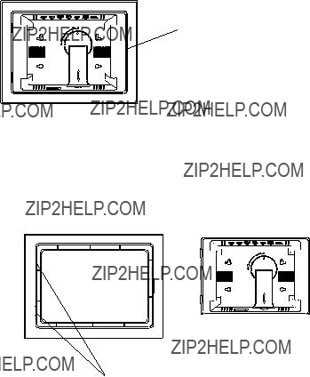
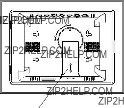
L. Removal and Installation Interchangeable Frames
Remove
Remove the current frame attached to the unit. Refer to the illustra- tion below:
Press here then remove the cover.
Installation
Please refer to the illustration below:
Insert the unit into the left cover slots first then lower the right side of the unit until it comes in contact with the frame. Press the plastic frame on the right of the unit. The lock position is indicated by a click.
13
M. SPECIFICATIONS
Photo format: JPEG
Panel size: 9 Inch
Power source: DC 9V
Power consumption: 5 W
Operating temperature: 41~95??F, 5~35??C
Weight : 0.78 Kg
Dimensions (W x H x D): 12.6 X9.02 X 1.34 inches 317 X 229 X 34mm
14
N. Troubleshooting
15

90 DAY LIMITED WARRANTY
Applies to Audiovox Video Products
AUDIOVOX ELECTRONICS CORP. (the Company) warrants to the original retail purchaser of this product that should this product or any part thereof, under normal use and conditions, be proven defective in material or workmanship within 90 days from the date of original purchase, such defect(s) will be repaired or replaced with reconditioned product (at the Company's option) without charge for parts and repair labor. A game controller, if supplied, is similarly warranted for ninety (90) days.
To obtain repair or replacement within the terms of this Warranty, the product is to be delivered with proof of warranty coverage (e.g. dated bill of sale), specification of defect(s), transportation prepaid, to the Company at the address shown below.
This Warranty does not extend to the elimination of externally generated static or noise, to correction of antenna problems, to costs incurred for installation, removal or reinstallation of the product, or to damage to digital memory/media devices, gaming devices, discs, speakers, accessories, or electrical systems.
This Warranty does not apply to any product or part thereof which, in the opinion of the
Company, has suffered or been damaged through alteration, improper installation, mishan- dling, misuse, neglect, accident, or by removal or defacement of the factory serial number/ barcodelabel(s). THEEXTENTOFTHECOMPANY'SLIABILITYUNDERTHISWARRANTYIS
LIMITEDTOTHEREPAIRORREPLACEMENTPROVIDEDABOVEAND,INNOEVENT,SHALL
THECOMPANY'SLIABILITYEXCEEDTHEPURCHASEPRICEPAIDBYPURCHASERFORTHE
PRODUCT.
This Warranty is in lieu of all other express warranties or liabilities. ANY IMPLIED WARRAN-
TIES,INCLUDINGANYIMPLIEDWARRANTYOFMERCHANTABILITY,SHALLBELIMITEDTO
THE DURATION OF THIS WRITTEN WARRANTY. ANY ACTION FOR BREACH OF ANY
WARRANTYHEREUNDERINCLUDINGANYIMPLIEDWARRANTY OF MERCHANTABILITY
MUST BE BROUGHT WITHIN A PERIOD OF 24 MONTHS FROM DATE OF ORIGINAL
PURCHASE. INNOCASESHALLTHECOMPANYBELIABLEFORANYCONSEQUENTIALOR
INCIDENTALDAMAGESFORBREACHOFTHISORANYOTHERWARRANTY,EXPRESSOR
IMPLIED, WHATSOEVER. No person or representative is authorized to assume for the Company any liability other than expressed herein in connection with the sale of this product.
Some states do not allow limitations on how long an implied warranty lasts or the exclusion or limitation of incidental or consequential damage so the above limitations or exclusions may not apply to you. This Warranty gives you specific legal rights and you may also have other rights which vary from state to state.
U.S.A. : AUDIOVOX ELECTRONICS CORPORATION, 150 MARCUS BLVD, HAUPPAUGE, NEW YORK 11788 !
CANADA: CALL
?? 2008 Audiovox Electronics Corporation
16