MODEL
WITH WIRED COMMANDER
COMPACT
DIGITAL AUDIO
INSTALLATION MANUAL
MODEL
WITH WIRED COMMANDER
COMPACT
DIGITAL AUDIO
INSTALLATION MANUAL

PACKING LIST
MAIN UNIT
CD Changer
INSTALLATION PARTS
1 pc.
ACCESSORIES
1

BEFORE INSTALLING THE UNIT
Transport Lock Screws
The mechanism in the CD changer is "locked" into place during shipment by the 4 transport screws. Be sure to remove the screws prior to installation.
Retain these screws for future use when transporting the unit for service/maintenance.
l Caution l
After removing the transport lock screws, place the supplied seals over the screw holes. These seals are used to keep dust out of the unit, which could cause a malfunction.
Installation and Wiring Precautions
4
5
Be careful not to damage the car wiring.
l Be sure to use the supplied screws.
lBe careful not to snag any wires when tightening screws.
lDo not use any of the screws that are part of the brake or steering system, to install the unit.
2

INSTALLATION
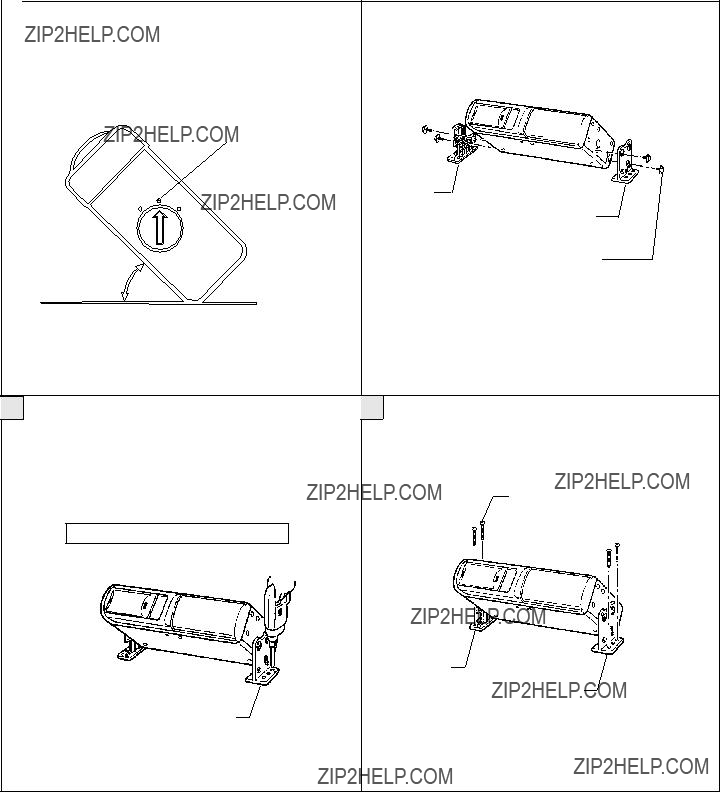
The unit can be installed horizontally, vertically or at a 45?? angle. The position of the
HORIZONTAL INSTALLATION
Set the
position "H"
45?? H
V 
VERTICAL INSTALLAITON
Set the
position "V"
H
45?? ANGLE INSTALLATION
Set the
position "45??"
45??
PROCEDURE FOR HORIZONTAL INSTALLATION
1 Attach a mounting bracket to each side of the unit, using the 4 hex head bolts with washer base.
45?? H
V 
Bracket
NOTE: Make sure
2 Determine the mounting location, and drill four mounting holes.
NOTE: If mounting surface is carpeted, use caution when drilling holes to prevent drill bit from catching on carpet. Cut holes in carpet before drilling into
Never mount the unit near the fuel tank.
3 Secure the unit in place, using four large
Use RTV (silicone sealer) on screw threads or around the holes to prevent moisture intrusion.
Bracket
Drill holes 1/8" (4mm) in diameter.
Bracket
3

PROCEDURE FOR VERTICAL INSTALLATION
Note
If the
1
3
position "V"
Bracket
Hex head bolt with washer base
Bracket
Bracket
Drill holes 1/8" (4mm) in diameter
4
PROCEDURE FOR 45?? ANGLE INSTALLATION
Note
If the
position "45??"
45??
3 Determine the mounting location, and drill four mounting holes.
NOTE: If mounting surface is carpeted, use caution when drilling holes to prevent drill bit from catching on carpet. Cut holes in carpet before drilling into
Never mount the unit near the fuel tank.
Bracket
Bracket
Hex head bolt with washer base
4 Mount the unit in place, using four large
Use RTV (silicone sealer) on screw threads or around the holes to prevent moisture intrusion.
Bracket
Bracket
Drill holes 1/8" (4mm) in diameter
5
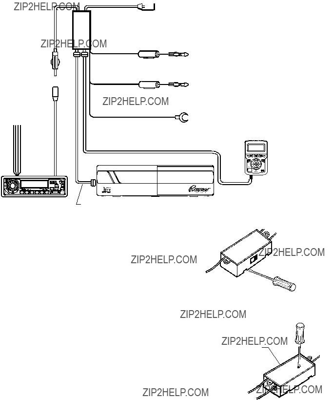
SYSTEM WIRING AND ADJUSTMENT
RF output (89.1MHz or 88.7MHz)
Antenna socket
To +12V ACC, Speakers, etc.
Fuse 2A
Fuse 5A
Commander connection cord
+12 volt Accessory/Switched (ORANGE w/WHITE STRIPE)
Connect this wire to a point which is energized when the ignition switch is turned to the "ON" or "ACCESSORY" position.
+12 volt Constant (GREEN w/WHITE STRIPE)
Connect this lead to the cable to which power is continu- ously supplied and which has been passed through the vehicle's fuse block.
Ground (BLACK)
Screw this to a metal part of the vehicle. Clean connecting area of paint, dirt, etc. A poor ground connection can cause incorrect or noisy operation.
Wired
Commander
FM Radio
ADJUSTMENT OF FM MODULATOR OUTPUT FREQUENCY
lIf there is interference from a local station or a clear signal cannot be obtained on 89.1 MHz., change the position of the frequency select switch on the side of the FM Modulator and tune the radio to 88.7 MHz. when using the CD changer.
lSelect the frequency before mounting the FM Modulator.
lRadio sensitivity may be slightly reduced when the FM Modulator is connected.
ADJUSTMENT OF FM MODULATOR AUDIO LEVEL
The audio level from the modulator is
1.With the CD changer off, tune to an FM station and adjust the volume control on the radio to a normal listening level.
2.Leaving the volume control at the setting, turn on the CD changer and tune the radio to the modulator output frequency (89.1 or 88.7 MHz.).
3.Select a LOUD section of the CD. If the volume level is comparable to that of the FM station in step 1, no adjustment is necessary. If it is noticeably louder or more quiet than that of the radio station, use a # 0 Phillips screwdriver to adjust the "AUDIO LEVEL" control on the modulator so that the CD changer volume is comparable to that of the radio station.
IMPORTANT: If the modulator audio level is adjusted too high, it may result in unacceptable levels of distortion during loud sections of CD's. If set too low, it may result in poor signal/noise levels during CD changer operation.
 FM Modulator
 Slide Switch
Move to 88.7M Position
#0 Phillips Screwdriver 
FM Modulator
6

VEHICLE WIRING
IMPORTANT - Some import cars use a special dual antenna ???Diversity" system. If your car has this type of antenna system, you will find the antenna cable will not fit the socket on the FM modulator. Use of the
Assistance for a special adaptor. This adaptor can also be purchased at most car stereo installation center.
+12V Accessory / Switched (ORANGE w/WHITE STRIPE)
Connect this wire to a terminal which is energized when the ignition switch is turned to the "ON" or "ACCESSORY" position.
+12V Constant (GREEN w/WHITE STRIPE)
Connect this wire to a terminal which is always energized.
To FM radio antenna
Commander connection cord
Fuses
Ground (BLACK)
Attach this wire to the chassis of the car. Be sure that the surface is free of paint, and is not rusty. If a proper ground connection is not made, the CD changer may not operate correctly and stray noise may be picked
up by the unit.
CD changer
 DIN cable
MOUNTING THE FM MODULATOR
Install the FM Modulator to the mounting surface with the small
MOUNTING THE WIRED COMMANDER
1.Determine where the commander unit will be located.
2.Be sure that the mounting surface where the commander unit will be located is clean and dry.
3.Remove the protective paper from the back of the Velcro strip.
4.Apply the commander unit to the desired location.
After completing all connections, press the RESET button on the commander unit.
Wired Commander
 Velcro Strip
FM Modulator