Copyright Information
No part of this manual, including the products and software described in it, may be reproduced, transmitted, transcribed, stored in a retrieval system, or translated into any language in any form or by any means, except documentation kept by the purchaser for backup purposes, without the express written permission of ASUS- TeK COMPUTER INC. (???ASUS???).
ASUS PROVIDES THIS MANUAL ???AS IS??? WITHOUT WARRANTY OF ANY KIND, EITHER EX-
PRESS OR IMPLIED, INCLUDING BUT NOT LIMITED TO THE IMPLIED WARRANTIES OR CON-
DITIONS OF MERCHANTABILITY OR FITNESS FOR A PARTICULAR PURPOSE. IN NO EVENT
SHALL ASUS, ITS DIRECTORS, OFFICERS, EMPLOYEES OR AGENTS BE LIABLE FOR ANY IN-
DIRECT, SPECIAL, INCIDENTAL, OR CONSEQUENTIAL DAMAGES (INCLUDING DAMAGES FOR
LOSS OF PROFITS, LOSS OF BUSINESS, LOSS OF USE OR DATA, INTERRUPTION OF BUSINESS
AND THE LIKE), EVEN IF ASUS HAS BEEN ADVISED OF THE POSSIBILITY OF SUCH DAM-
AGES ARISING FROM ANY DEFECT OR ERROR IN THIS MANUAL OR PRODUCT.
Product warranty or service will not be extended if: (1) the product is repaired, modified or altered, unless such repair, modification of alteration is authorized in writing by ASUS; or (2) the serial number of the product is defaced or missing.
Products and corporate names appearing in this manual may or may not be registered trademarks or copy- rights of their respective companies, and are used only for identification or explanation and to the owners??? benefit, without intent to infringe.
SPECIFICATIONS AND INFORMATION CONTAINED IN THIS MANUAL ARE FURNISHED FOR
INFORMATIONAL USE ONLY, AND ARE SUBJECT TO CHANGE AT ANY TIME WITHOUT NO-
TICE, AND SHOULD NOT BE CONSTRUED AS A COMMITMENT BY ASUS. ASUS ASSUMES NO
RESPONSIBILITY OR LIABILITY FOR ANY ERRORS OR INACCURACIES THAT MAY APPEAR
IN THIS MANUAL, INCLUDING THE PRODUCTS AND SOFTWARE DESCRIBED IN IT.
Copyright ?? 2004 ASUSTeK COMPUTER INC. All Rights Reserved.
Limitation of Liability
Circumstances may arise where because of a default on ASUS??? part or other liability, you are entitled to recover damages from ASUS. In each such instance, regardless of the basis on which you are entitled to claim damages from ASUS, ASUS is liable for no more than damages for bodily injury (including death) and damage to real property and tangible personal property; or any other actual and direct damages resulted from omission or failure of performing legal duties under this Warranty Statement, up to the listed contract price of each product.
ASUS will only be responsible for or indemnify you for loss, damages or claims based in contract, tort or infringement under this Warranty Statement.
This limit also applies to ASUS??? suppliers and its reseller. It is the maximum for which ASUS, its suppliers, and your reseller are collectively responsible.
UNDER NO CIRCUMSTANCES IS ASUS LIABLE FOR ANY OF THE FOLLOWING: (1) THIRD-
PARTY CLAIMS AGAINSTYOU FOR DAMAGES; (2) LOSS OF, OR DAMAGE TO, YOUR RECORDS
OR DATA; OR (3) SPECIAL, INCIDENTAL, OR INDIRECT DAMAGES OR FOR ANY ECONOMIC
CONSEQUENTIAL DAMAGES (INCLUDING LOST PROFITS OR SAVINGS), EVEN IF ASUS, ITS
SUPPLIERS OR YOUR RESELLER IS INFORMED OF THEIR POSSIBILITY.
English
Centralized Network
Management
GigaX Management Software
User???s Manual
Note: Provides clarification or nonessential information on the current topic.
Definition: Explains terms or acronyms that may be unfamiliar to many readers. These terms are also included in the Glossary.
WARNING: Provides messages of high importance, including messages relating to personal safety or system integrity.
2.2 Front Panel
The front panel contains LED indicators that show the status of the unit.
English
2.3 Rear Panel
The rear panel contains the ports for the unit???s power connections.
Label Function
POWER Connects to the supplied power cord
3. Plug the male end of the AC power cord into a wall outlet or a power strip.
the window will show the MAC addresses of the switches discovered by the CNM as Figure 3.3.
Figure 3.3. Available Switches
4.Select the switch you want to manage by clicking on the MAC address, then you can start to configure the switch by CNM.
5.If the CNM cannot discover the switch you want to manage, please repeat step 1 to 4 again.
Note: The switch must be powered on and connect to your network before starting the CNM.
4.2 Functional Layout
The CNM window consists of three separate frames. The top frame has switch logo and front panel as shown in Figure4.2. This frame remains on the top of the browser window all the times and updates the LED status periodically. The LED definition has been described as Table 2.1. Each port shows different states by different colors, shown as Table 4.1.
Figure 4.2. Top frame
Table 4.1. Description of Port Color
The left frame, a topology frame as shown in Figure 4.3, contains all the NICs in the manage station. Each NIC has a tree view to show the switches that are discovered by CNM. You can click on any of these to display a specific configuration of the switch.
Figure 4.3. A Topology Frame
Click on the NIC, it shows the topology of the switches in the network. If multiple switches are cascaded, the tree view will show the relationship of those switches as Figure 4.4.
Figure 4.4. Tree view of the network topology
The right frame displays the specified switch configurations or graphics for the statistics. That is, it displays different configuration layout for different model. Section 4.5 will describe 1024P configuration in details. You have to specify a switch by clicking one switch in the topology list.
4.3 General Settings for CNM
There are menu bar and tool bar on the top of the CNM window. They offer general settings for CNM.
The Topology item provides the general network discovery, manually add or delete switches, and load or save the current discovered topology.
The Setup item provides the update interval and password settings.
The Help item provides CNM information and instructions
4.3.1 Topology
Figure 4.5. Topology
Topology is to control the actions of the topology frame. A couple of things you can do to the topology frame are listed as following:
3.Discovery: discover all the 1024Ps in all the networks that your CNM station is connecting to. The discovery result will display in the topology
frame. There is a corresponding function icon  in the tool bar.
4.Update: detect if the communications between the CNM station and the
discovered switches is good or not. The switch icon will show  to indicate that the communication is broken.
switch to attach to, give the switch MAC and name, and an authentication key as the password if you don???t use the default one (2379), then click OK to finish the action. However, a manually added switch does not mean it can be configured or discovered by CNM. The function provides a way to add a known switch to topology list once the CNM cannot discover the switch. There is a tool bar button for it..
Figure 4.6. Add Switch
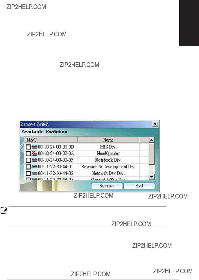
6.Remove Switch: you can remove any switch in the topology list manually through this function. It pops out a switch list and check those switches you want to remove. Please refer to Figure 4.7 for the switch list window.
Figure 4.7. Remove Switch
Figure 4.8. Setup
CNM polls the switch status periodically, the polling interval can be adjusted.
1.Auto Update Time Interval: as Figure 4.9, a proper value can be set. The auto update time interval is used to poll the switch statistics and link status on the top of the window. The interval value could be adjusted from 0 to 300 seconds. 0 means no polling at all. There is a tool bar button for it.
Figure 4.9. Auto Update Time Interval
4.3.3 Help
Help shows you the CNM user guide and current version.
4.4 Switch Topology
The switch topology frame is on the left part of the CNM window. It shows the discovered switches and the relationship among them. Each presents a NIC interface. The interface name and MAC address is shown after the.
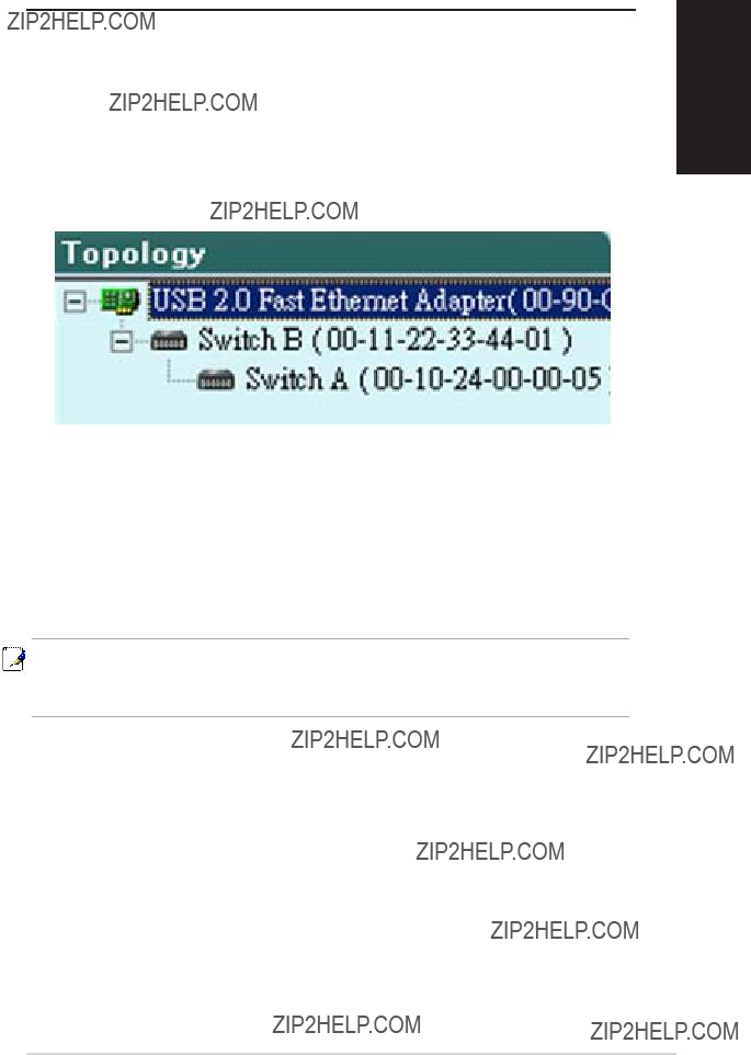
The switch topology shows the relationship among the switches in a tree view. That is, if a switch A has connections to switch B and your NIC, then a cascade tree will display as Figure 4.10.
Figure 4.10. Switch Relationship
In this way, you can find the relationship among the switch. It helps design and debug your network. Each is a switch with name and MAC address followed. You can assign a name to the switch by click the right button on the mouse while the mouse is point to the switch MAC address.
Note: All the switch names are kept in CNM file, but not in the switches. So if you use CNM to manage the same switch on another management station, the name may be different because the switch does not keep its name.
4.4.1 Topology Discovery
The topology discovery is done by user???s request. That is, no auto update is executed for the topology change. This will reduce the network traffics since the discovery generates some packets to query the switches.
4.4.2 Switch Add and Removal
Discovery action will create the topology tree by all the discovered switches. The default password will be used in the discovery process. Sometimes you may have a switch with another password that is different from the default one. In this case, the switch cannot be discovered by the default password. You need to add a switch to the topology manually.
Figure 4.11 shows the window to add a switch. The are a couple of columns to fill to add a switch successfully.
Figure 4.11. Add Switch
1.Adapter: select the corresponding adapter to add a switch under it.
2.Switch: check the box if you want the new switch to be added under a specified switch in the topology tree. The manually added switch will be moved to a right place to show the relationships in the topology after a successful discovery.
3.MAC: the most important information is the MAC address. If the MAC is wrong, the new added switch can not be accessed by CNM.
4.Name: a good name may remind you something about the switch. However, the switch name is good only in the same CNM file. So the name may not be unique when you use different CNM files to do discover.
Once a switch is added to the topology tree, you can find it in the corresponding place. You have to left click the switch symbol to switch the current status/configuration window from other switch to this switch. If the communication is good, you can see the linking status window on the right frame of the CNM window, and the topology tree will display the switch symbol in a correct place to show the relationship. If CNM cannot discover the manually added switch, then a  will attach to the switch to show it is not reachable to the CNM.
Figure 4.12 shows the window to remove switches, just check the box before the switch to select those you want to remove, click the remove icon to start the action. All the corresponding switches will be removed and the tree branch after the removed switches are moved up to under the adapter. A discovery action will update the topology tree for the current network. You may find the removed switches are back to the topology tree because they are discovered again.
Figure 4.12. Remove Switch
Note: The removed switch may be added back to the topology tree because the discovery action finds the switch in the network. This is normal because the switch is still working.
4.4.3 Topology Load and Save
A topology can be saved for later reference. The CNM starts with a default topology file. After the discovery action, it shows the update network topology. You can save it in a good file name and load it when you need it.
4.6.3 Change Password
A valid password consists of 4 digits, from 0 to 9, and a to f. The authenticator does not check upper case or lower case. For example, password ???12ab??? is treated as ???12AB???. Once the password gets changed, CNM will use the password to retrieve the information about the switch.
If the password is forgotten, please refer to 3.3.2 to reset the password in the switch. After it, you have to remove the switch from the topology and discover the switch again.
After changing the password, CNM will show a dialog box for administrators to save the topology or not. If not, administrators will have to do two jobs when CNM starts up next time. First, manually add the switch according to section 4.4.2. Second, change password again and replace 0x2379 with correct one.
Figure 4.14b. Change Password
Since password was modified, administrators have to login to the switch. Or administrators will not be able to control the switch. The page is shown as Figure 4.14b.
4.6.5 Save
Save all the configurations to a local file for future reference. Once you create a configuration file in CNM, you can use it to apply to the other switches to save your time. It is also a backup file for configuration. It is recommended to have a good file name to identify that the configuration is for the certain switch(es).
Figure 4.16. Save Configuration
4.6.6 Apply and Save
It applies all the current settings in CNM to the switch and save them in the switch permanently. It is recommended to back up the existed switch configurations before applying a new configuration to the switch.
Figure 4.17. Apply Configuration
4.7 Configuration
The Configuration menu provides the configuration for all the functions that the switch can supports, like physical interface, link aggregation, bandwidth control, traffic control, VLAN, IGMP snooping and QoS.
To keep all the new configurations and save the bandwidth for communications, each configuration page will not retrieve information from switch until you click the Reload button. In some configuration pages, you can select the ports to reload the information from the switch.
4.7.1 Physical Interface
Figure 4.18. Physical Interface
Figure 4.18 shows the configuration for each port. Select the ports you want to configure or reload information from the switch by clicking on the check boxes in front of the ports, then click on Config to set the configuration for the ports, or click on Reload to retrieve configuration from the switch, or click on Apply to apply the new settings to the switch. Some settings you can do to the physical interface
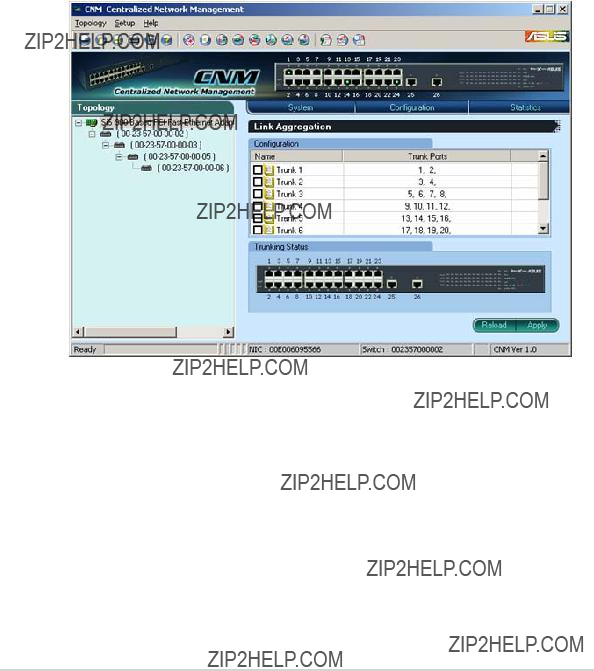
Figure 4.19. Link Aggregation
Link aggregation creates new virtual links with more bandwidth. For example, port 1 and 2 can work together as one link to another device. The new virtual link has 200Mbps bandwidth. The switch provides 8 groups of link aggregations shown on the top of figure 4.19.
Click on the Reload button to retrieve the configuration from switch. The checked trunk group means this group has been activated. You can check the trunk group to enable new trunk or uncheck the trunk group to disable the trunks. Click on Apply to make them effective in the switch.
The Trunking Status shows the ports work as trunk ports currently. A green light in the port means the port is working as trunk port properly, otherwise it shows no light.
4.7.3 Bandwidth
Figure 4.20. Bandwidth Configuration
1024P provides TX/RX bandwidth control for each port. Please reload the configuration before you start to set up new configuration. The page is shown as figure 4.20.
Select the ports you want to configure, then select proper bandwidth for TX/ RX directions. Click on Apply to apply to the switch.
English
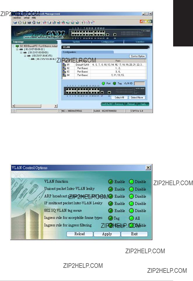
Figure 4.21. VLAN
All VLAN behavior will be influenced by VLAN control option. Click Control Option and a window will pop out as Figure 4.22. Enable or disable these options carefully, these options are global setting for VLAN
Figure 4.22. VLAN Control Options
and group address member ports into the multicast address table. The table is combined with L2 MAC table, so the maximum entry is 8K. The valid port member will auto aging out after about 5 minute idle. Figure 4.23 shows the page.
Figure 4.23. IGMP Snoop
4.8 Statistics
Statistics offer Port Traffic, Traffic History and Comparison charts. The switch has 3 counters for 8 kinds of statistics. So you cannot see all the statistics at the same time. That is, the old statistics data will be gone if you start to use the counter for another statistics.
4.8.1 Port Traffic
Select port number, the statistics item and color to draw the traffic chart. The chart will be auto updated in the time interval you set in Setup menu. Refer to 4.3.2 for time interval setup.
Press the Draw Traffic Chart button to start drawing.
Figure 4.25. Port Traffic
4.8.2 Traffic History
Select the statistics item, ports and colors you want to see in the chart, then press the Draw Traffic Chart button to start the drawing. The chart will be auto updated in the time interval you set in Setup menu. Refer to 4.3.2 for time interval setup.
Figure 4.26. Traffic History
4.8.3 Comparison
Select the statistics item to do comparison for port 1 to 26. Press the Draw Traffic Chart button to start the drawing. The chart will be auto updated in the time interval you set in Setup menu.
Figure 4.27. Port Comparison


 or
or  to assign port members.