K Service Source
Workgroup Server 9150
Workgroup Server 9150
Workgroup Server 9150/120
K Service Source
Workgroup Server 9150
Workgroup Server 9150
Workgroup Server 9150/120

K Service Source
Basics
Workgroup Server 9150

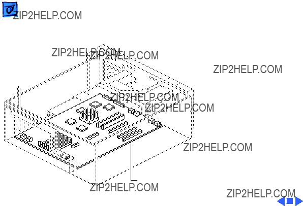
Rear Panel Connectors

Logic Board Connectors
Note: The order of the cache and ROM SIMMs will vary according to the manufacturing date of the logic board. Be sure to correctly identify the cache SIMM, which has four chips on both sides, and remove it before returning the logic board to Apple for repair. Do NOT remove the ROM SIMM before returning the logic board.
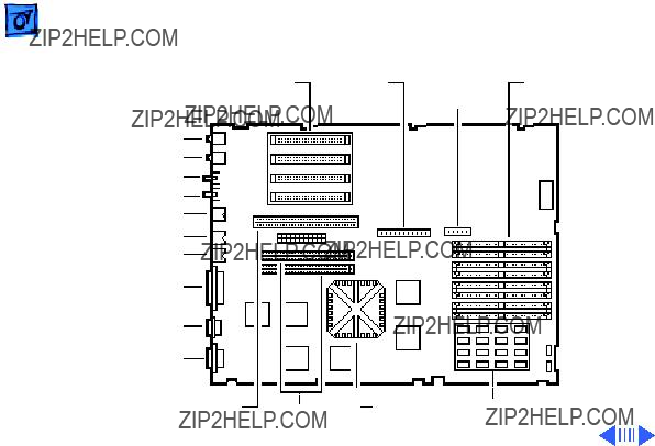
WS 9150
NuBus Internal
Slots SCSI
Connector
Sound Out
Sound In
Sound In Left
Sound In Right
ADB
Printer
Modem
SCSI
Floppy DRAM
Connector SIMMs
16 MB Soldered DRAM

Note: The order of the cache and ROM SIMMs will vary according to the manufacturing date of the logic board. Be sure to correctly identify the cache SIMM, which has four chips on both sides, and remove it before returning the logic board to Apple for repair. Do NOT remove the ROM SIMM before returning the logic board.
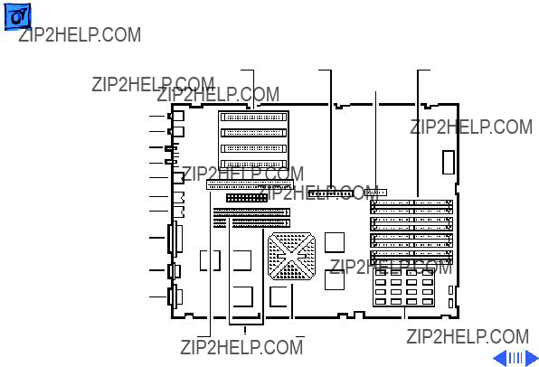
WS 9150/120
NuBus Internal
Slots SCSI
Connector
Sound Out
Sound In
Sound In Left
Sound In Right
ADB
Printer
Modem
Floppy DRAM
Connector SIMMs
8 MB Soldered DRAM

Important: The WS 9150/120 logic board has a thermoelectric cooling device that attaches directly to the microprocessor's heatsink. You can identify this cooling device by the black and red wires that run to the right of the heatsink and plug into the logic board via a keyed connector. This device is not a serviceable item. Do not unplug this device or you may damage the logic board. Also note that the order of the cache and ROM SIMMs may vary. Be sure to correctly identify the cache SIMM and remove it before returning the logic board to Apple for repair. Do NOT remove the ROM SIMM before returning the logic board.

RAID Information
Apple RAID Software
Apple RAID (Redundant Array of Independent Disks) software protects data from loss during a disk failure and enhances the speed of data storage and retrieval. It is available for all Power Macintosh Workgroup servers.
Data protection is achieved through disk mirroring, a data storage scheme in which identical data is stored on two different disks. Apple RAID can also be configured for disk striping, a data storage scheme in which successive units of data are transferred to several disks at one time.

If you plan to install the Apple RAID software on an existing Power Macintosh Workgroup Server, or if you are reinitializing an existing Apple RAID drive, keep in the mind the following:
???If you wish to use your server???s startup disk for Apple RAID, do not install the Apple RAID program on your startup disk until you have initialized and set up new volumes on that disk. Before you initialize the startup disk, backup all valuable data.
???You must reinitialize all disks on which you will use Apple RAID volumes. Initializing with Apple RAID removes all data, so be sure to backup your disks first.

K Service Source
Speci???cations
Workgroup Server 9150

Processor
CPU
9150:
9150/120:
80 MHz PowerPC 601 RISC microprocessor
32K of
Requires system software version 7.1.2 or later
120 MHz PowerPC 601 RISC microprocessor
32K of
Requires system software version 7.5 or later

Memory
RAM

Cache
9150:32K
9150/120:32K
Clock/Calendar CMOS custom chip with

Floppy Drive
Hard Drive
9150:
9150/120:
Tape Drive
Disk Storage
1.4 MB Apple SuperDrive Manual Insert
500 MB, 1 GB, or 2 GB hard drive standard; room for a total of five internal hard drives
Two 1 GB hard drives or one 2 GB hard drive standard; room for a total of five internal hard drives
Optional

9150:Internal AppleCD 300 Plus
9150/120:Internal AppleCD 600

SCSI
Serial
Apple Desktop Bus
Ethernet
I/O Interfaces
One SCSI port;
Supports maximum of seven internal and seven external SCSI devices
Two
One Apple Desktop Bus (ADB) port;
One Ethernet port;


Keyboard
Mouse
Microphone
I/O Devices
Standard, extended, or adjustable keyboard
Keyboard draws
ADB Mouse II; Draws up to 10 mA
Electret, omnidirectional; output voltage is 4 mV, peak to peak, at normal value; does not use Apple PlainTalk microphone

Video Display
Video Support
Supports monochrome, color, VGA, and SVGA formats, including
???Macintosh 12" Monochrome Display (640 x 480)
???Macintosh 12" RGB Display (512 x 384)
???AppleColor
???Apple AudioVision 14 Display (640 x 480)
???Macintosh Color Display (640 x 480)
???Macintosh 15" Portrait Display (640 x 870)
???Macintosh 16" Color Display (832 x 624)

Electrical
A/C Line Input
Voltage
Input Line
Frequency
Input Power
Power Supply DC
Output
600 W maximum, not including monitor power
303 W maximum


Environmental
Operating Temp
Storage Temp
Relative Humidity
Altitude

K Service Source
Troubleshooting
Workgroup Server 9150

General
The Symptom Charts included in this chapter will help you diagnose specific symptoms related to your product. Because cures are listed on the charts in the order of most likely solution, try the first cure first. Verify whether or not the product continues to exhibit the symptom. If the symptom persists, try the next cure. (Note: If you have replaced a module, reinstall the original module before you proceed to the next cure.)
If you are not sure what the problem is, or if the Symptom Charts do not resolve the problem, refer to the Flowchart for the product family.
For additional assistance, contact Apple Technical Support.

Cleaning Procedure for Card Connectors
A small number of cards for the Workgroup Server 9150 may contain residue on the gold edge connector pins, which may cause a variety of intermittent symptoms.
To correct the problem, inspect the connector pins with a magnifying glass. If you find residue, use a pencil eraser to gently clean the pins.

 TroubleshootingSymptom Charts/Power Supply - 3
Symptom Charts
Power Supply

Error Chords
1Disconnect SCSI data cable from hard drive and reboot system. If startup sequence is normal, initialize hard drive. If error chord still sounds, replace hard drive.
2Disconnect floppy drive cable from floppy drive and reboot system. If startup sequence is normal, replace floppy drive.
3Reseat ROM, RAM, and cache SIMMs, and reseat terminator card.
4Replace logic board. Retain customer???s SIMMs.
 TroubleshootingSymptom Charts/System - 5
System


Video
Screen is black, audio and drive operate, fan is running, and LED is lit
1Adjust brightness on monitor.
2Replace video cable.
3Try using
4Replace video card (if present).
5Clear parameter RAM. Hold down <Command> <Option> <P> <R> during startup but before ???Welcome to Macintosh??? appears.
6Replace SIMMs.
7Replace monitor. Refer to appropriate monitor manual to troubleshoot defective monitor.
8Reseat ROM, RAM, and cache SIMMs, and reseat terminator card.
9Replace logic board. Retain customer???s SIMMs.
10Replace power supply.


Partial or whole screen is bright and audio is present, but no video information is visible
1Replace video cable.
2Replace video card (if present).
3Clear parameter RAM. Hold down <Command> <Option> <P> <R> during startup but before ???Welcome to Macintosh??? appears.
4Replace monitor. Refer to appropriate monitor manual to troubleshoot defective monitor.
5Reseat ROM, RAM, and cache SIMMs, and reseat terminator card.
6Replace logic board. Retain customer???s SIMMs.

 TroubleshootingSymptom Charts/Floppy Drive - 13
Floppy Drive

 TroubleshootingSymptom Charts/Floppy Drive (Continued) - 14
Floppy Drive (Continued)
 TroubleshootingSymptom Charts/Floppy Drive (Continued) - 15
Floppy Drive (Continued)
 TroubleshootingSymptom Charts/Floppy Drive (Continued) - 16
Floppy Drive (Continued)

 TroubleshootingSymptom Charts/Hard Drive - 17
Hard Drive


 TroubleshootingSymptom Charts/Peripherals - 20
Peripherals

Peripherals (Continued)
Cursor moves, but clicking mouse button has no effect
1Replace mouse.
2Reseat ROM, RAM, and cache SIMMs, and reseat terminator card.
3Replace logic board. Retain customer???s SIMMs.

Peripherals (Continued)
1Remove duplicate system folders.
2Clear parameter RAM. Hold down <Command> <Option> <P> <R> during startup but before ???Welcome to Macintosh??? appears.
3If mouse was connected to keyboard, connect mouse to computer ADB port instead. If mouse works, replace keyboard.
4If mouse does not work in any ADB port on computer, replace mouse.
5Reseat ROM, RAM, and cache SIMMs, and reseat terminator card.
6Replace logic board. Retain customer???s SIMMs.

 TroubleshootingSymptom Charts/Peripherals (Continued) - 23
Peripherals (Continued)

 TroubleshootingSymptom Charts/Peripherals (Continued) - 24
Peripherals (Continued)
 TroubleshootingSymptom Charts/Miscellaneous - 25
Miscellaneous
 TroubleshootingSymptom Charts/Miscellaneous (Continued) - 26
Miscellaneous (Continued)

Macintosh does not display
Computer with 600i
1Exchange disc.
2Replace
1Verify that
2Replace SCSI data cable.
3Replace

K Service Source
Take Apart
Workgroup Server 9150
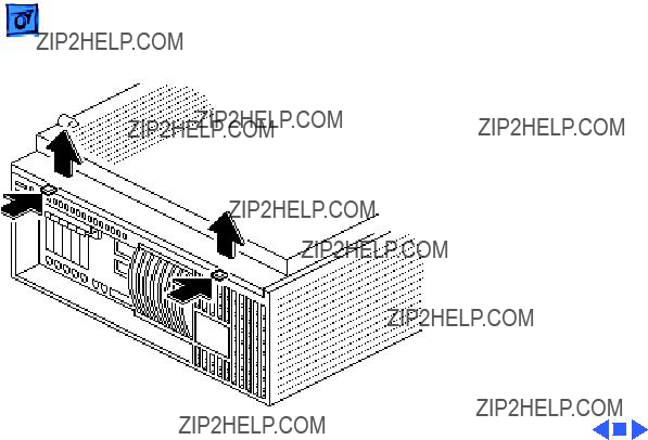
Cover
No preliminary steps are required before you begin this procedure.
Note: You must place the system on its side. Attempt- ing to remove the cover with the system standing may cause damage to the cover.
Press the two latches, lift the cover, and remove it from the computer.
Before you begin, remove the cover.
Caution: Review the ESD precautions in Bulletins/ Safety.
Note: For information on the

 Take Apart
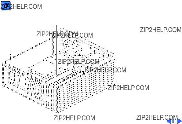
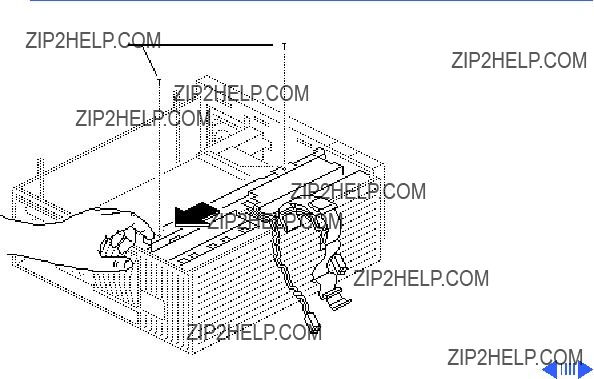
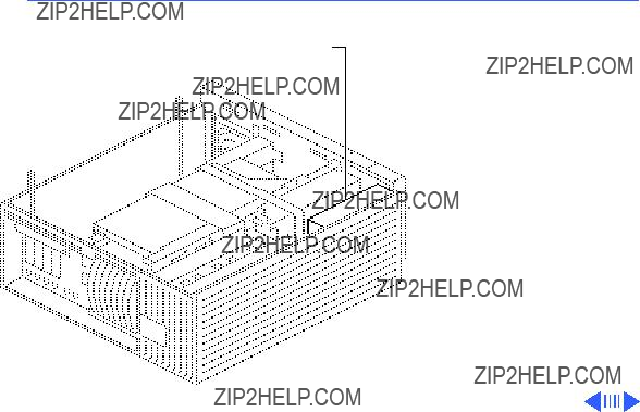
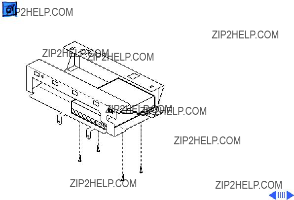
Drive
Shelf
3Remove the two screws that secure the
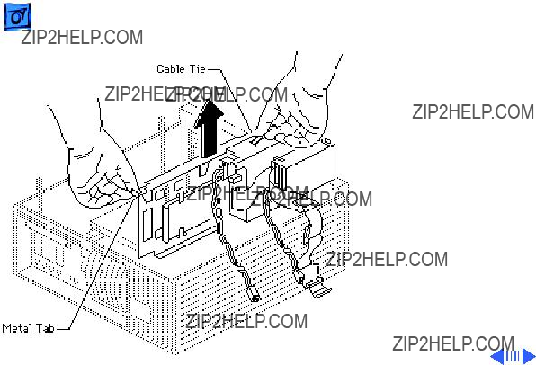
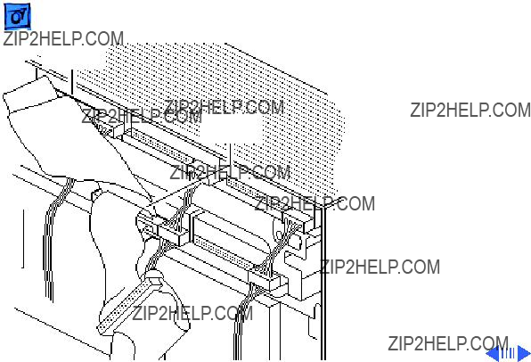
4Grasp the cable tie and the edge of the carrier and lift the

 Take ApartDrive Shelf - 6
 Take Apart
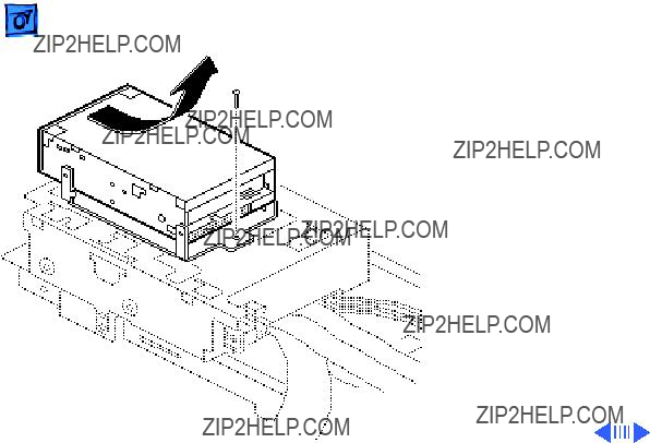
Drive Shelf
Screws
Drive Shelf - 8
2Remove the two screws securing the drive shelf to the inside frame.
3Slide the drive shelf toward the rear of the computer.
Drive
 Take ApartFront Panel - 11
Power
Supply
 Take ApartSpeaker - 13
 Take ApartFloppy Drive - 15

 Take ApartHard Drive - 17


 Take ApartTape Drive - 21


 Take ApartCD-ROM Drive - 24
Replacement Note: Run the
Drive ShelfCD-ROM power cable through the Velcro strap on the side of the drive shelf.

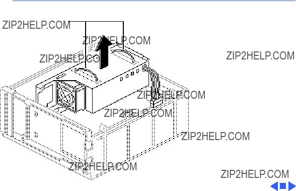
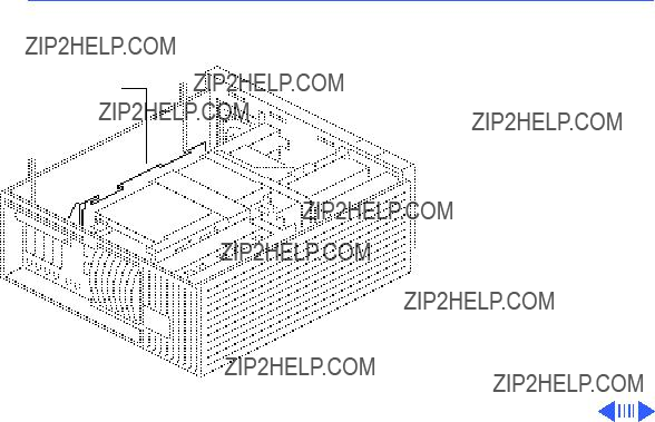
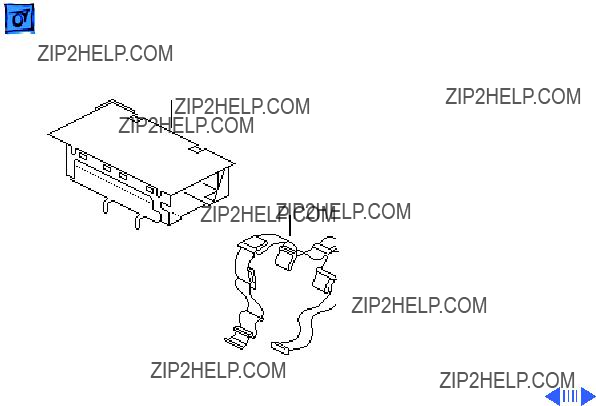
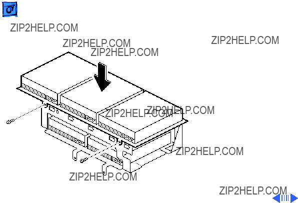
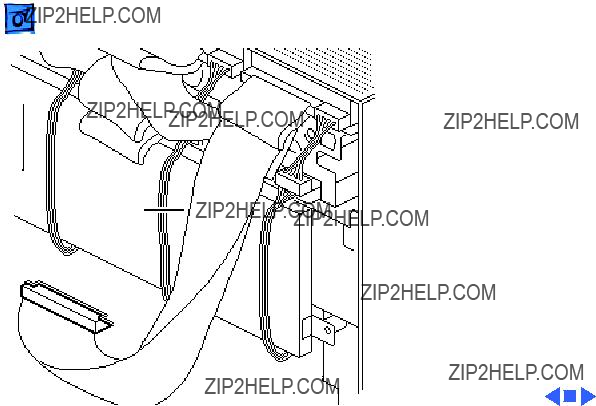
Power Supply
Power Supply
Before you begin, remove the following:
??? Cover
???
??? Drive shelf
Note: The WS 9150/120 has a processor fan that attaches to the underside of the power supply and plugs into the logic board. You must unplug this fan before removing the power supply.
Power Supply
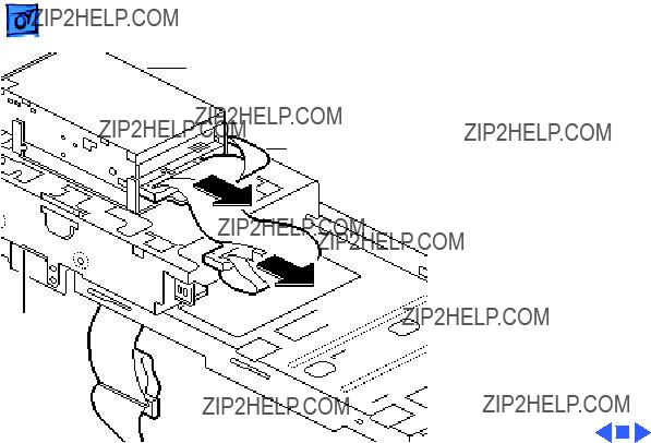
Bezel
Latch
Latch
3Release the two plastic latches on the inside of the
 Take Apart
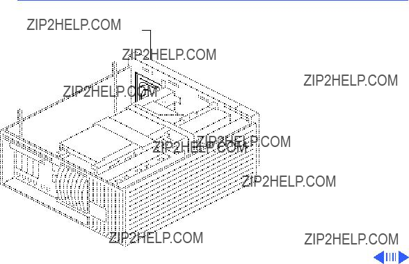
Handles
Power Supply - 29
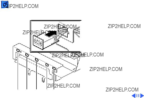
4Note: If you are servicing a Workgroup Server 9150/120, you must disconnect the processor fan from the logic board before removing the power supply. The processor fan attaches to the underside of the power supply.
Grasp the two handles and, pulling evenly, lift the power supply straight up out of the computer.
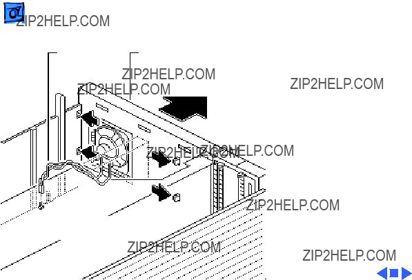
 Take ApartPower Supply Fan - 30
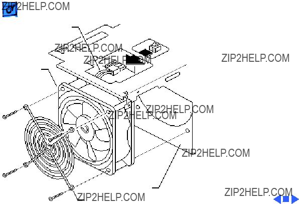
Fan Cable
Fan
Power Supply
Fan Grill
1Disconnect the fan cable from the power supply.
2Remove the four fan mounting screws.
3Remove the fan and fan grill from the power supply.

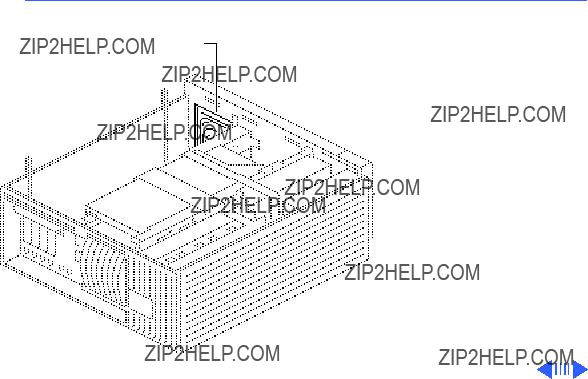
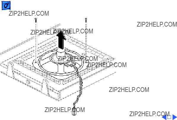
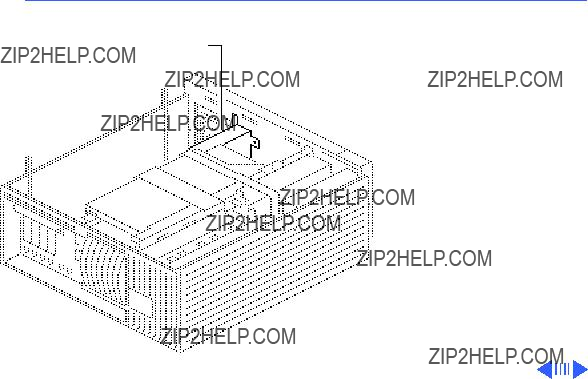
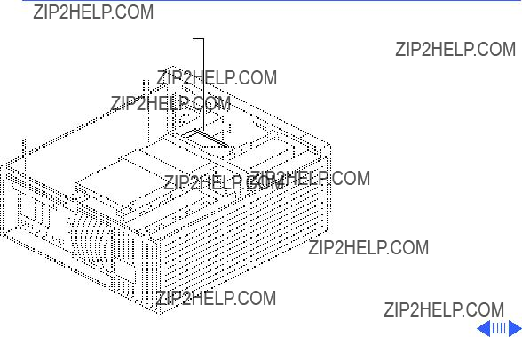
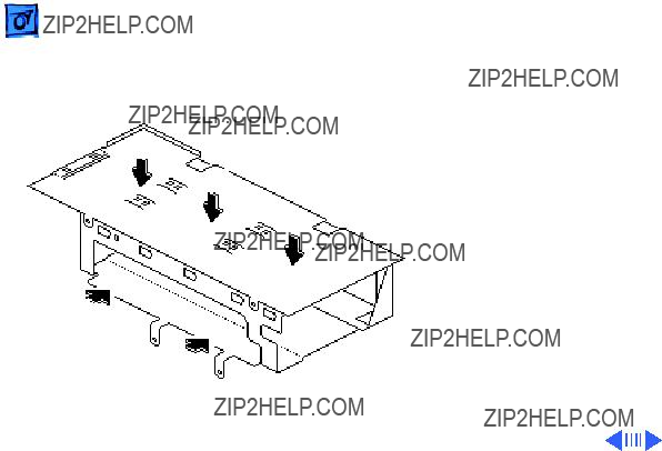
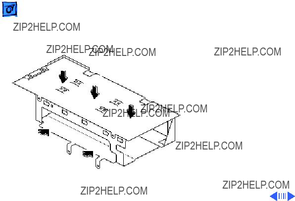
Processor Fan
Before you begin, remove the following:
??? Cover
???
??? Drive shelf
??? Power supply
Note: The processor fan attaches to the underside of the power supply and plugs into the logic board.

Power Supply

 Take Apart
NuBus Card
NuBus Cards - 35
NuBus Cards
Before you begin, remove the cover.
Caution: Review the ESD precautions in Bulletins/ Safety.
Caution: You must unplug the computer prior to removing or installing NuBus cards. Failure to unplug the computer could cause damage to the logic board and/or cards.
Logic Board
Before you begin, remove the following:
??? Cover
???
??? Drive shelf
??? Power supply
??? NuBus cards
Caution: Unplug the computer prior to removing Nubus cards or you may damage the logic board and/ or cards.
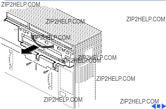
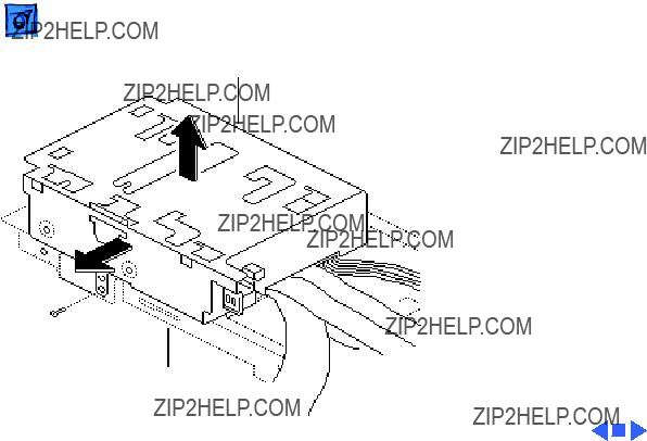
Logic Board

Logic Board
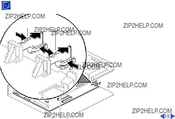
1Press in on the sides of the interrupt and reset switches and push them out of the case.

Latch
Logic Board
Keyswitch
Cable
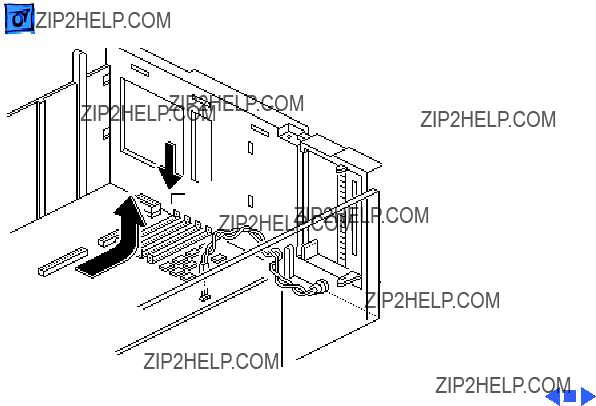
2Disconnect the keyswitch cable from the l ogic board.
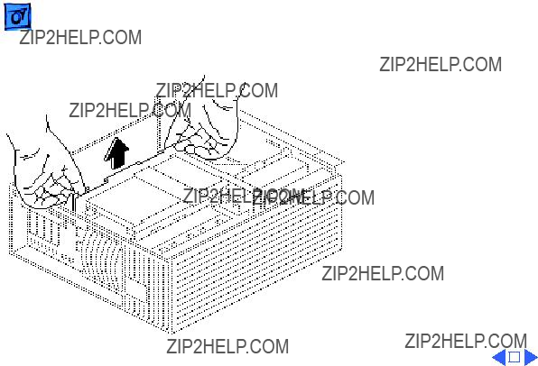
3Press down on the latch and slide the logic board toward the front of the computer.
4Lift the logic board, front first, from the computer.
Replacement Note:
Remove any DRAM SIMMs from the defective logic board and install them on the replacement logic board provided they are in
Latchmatching pairs. If there is a cache SIMM on the defective logic board, remove it and install it on the replacement board.
Logic Board
Keyswitch
Cable

K Service Source
Upgrades
Workgroup Server 9150
 Upgrades
NuBus Cards
NuBus Cards - 1
NuBus Cards
Before you begin, remove the cover.
Caution: Review the ESD precautions in Bulletins/ Safety.
Caution: You must unplug the computer prior to removing or installing NuBus cards. Failure to unplug the computer could cause damage to the logic board and/or cards.


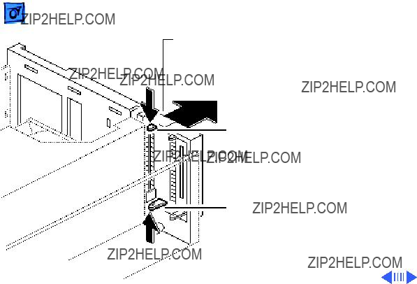
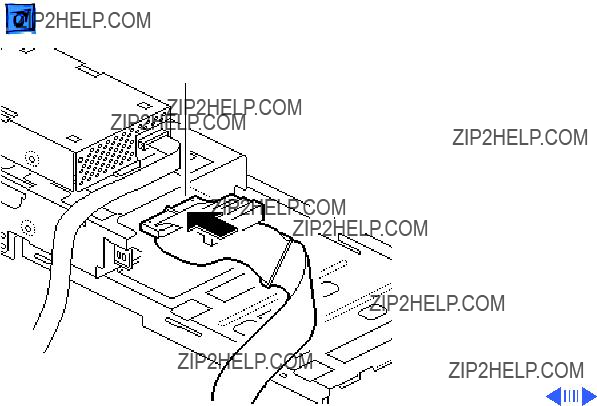
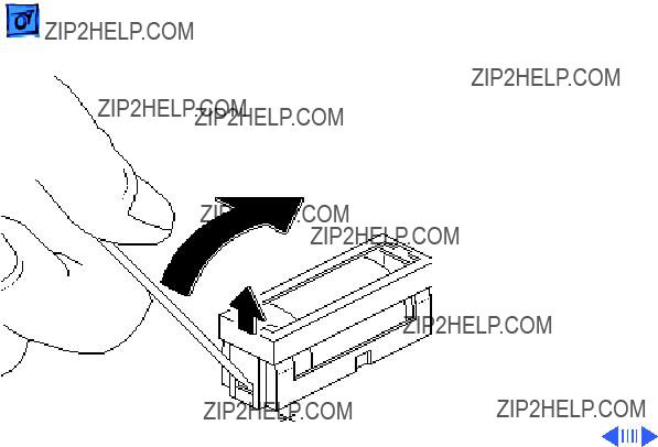
SCSI ID
Switch
3There are five openings in the bottom panel of the drive carrier for the SCSI ID switches. The openings are labeled
Note: The type of SCSI ID switch you install will depend on the drive type.
Install the SCSI ID switch for the first drive by feeding the connector end of the SCSI ID cable through the opening labeled A on the drive carrier.
E B D A C
SCSI ID
Switch
4Push in on the SCSI ID switch until it clicks into place.
5Repeat this procedure to install the remaining SCSI ID switches.
E B D A C
A
B
A
Caution: Be careful not to pinch the cables that run from the SCSI ID select switches.

 Upgrades
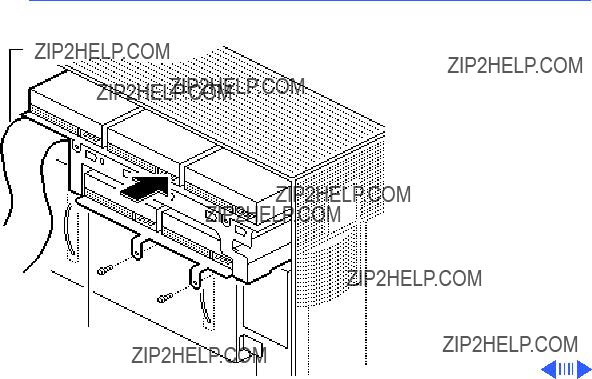
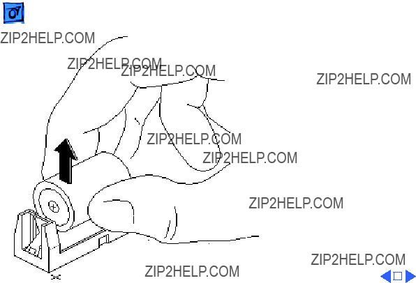
SCSI Cable
Hard Drive Upgrades - 13
13Hold up the
14Insert the drive carrier in the upper right area of the tower (above the power supply).
15Insert the two screws that secure the drive carrier to the metal frame. Tighten the screws.
Drive
Carrier

Slot E
Slot D
Slot B
Power Supply
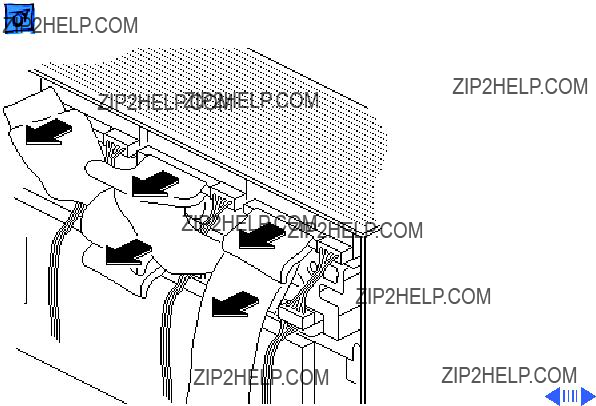
19Repeat the procedure on the previous page to connect the drives in slots D and B.
20Use the last hard drive power cable to connect the single drive in slot E.
Drive E
Connector
Drive B
Connector
21Attach the drive E connector on the five- drive SCSI cable to the hard drive in slot E.
22Fold over the cable and attach the drive B connector to the drive in slot B.

Drive D
Connector
Drive A
Connector
23Attach the drive D connector on the five- drive SCSI cable to the hard drive in slot D.
24Fold over the cable and attach the drive A connector to the drive in slot A.

Drive C
Connector
SCSI Cable

WS 9150 Upgrade
Before you begin, to upgrade a Quadra 900 or 950 computer to a WS 9150, you must install the WS 9150 logic board. Up- grading to the 120 MHz version of the WS 9150 also requires the installation of a processor fan.
Refer to the Logic Board and Processor Fan topics in Take Apart for installation instructions.
Logic Board
Logic Board
K Service Source
Additional Procedures
Workgroup Server 9150

 Additional ProceduresBattery Verification - 1

 Additional ProceduresBattery Replacement - 3


Reset Logic Board
Before you begin:
??? Remove the cover
??? Unplug the computer
Note: Whenever you have a unit that fails to power up, you should follow this procedure to reset the logic board before replacing any modules.
Caution: Review the ESD precautions in Bulletins/ Safety.
Lithium Battery

Lithium Battery


K Service Source
Exploded View
Workgroup Server 9150

Product family configurations may vary. For parts with asterisk (*), refer to parts list.
WS 9150