K Service Source
Power Mac G4/
Macintosh Server G4
Power Mac G4 (AGP Graphics/Gigabit Ethernet/Digital Audio/
QuickSilver/QuickSilver 2002/QuickSIlver 2002ED),
Power Mac G4 (PCI Graphics),
Macintosh Server G4
K Service Source
Power Mac G4/
Macintosh Server G4
Power Mac G4 (AGP Graphics/Gigabit Ethernet/Digital Audio/
QuickSilver/QuickSilver 2002/QuickSIlver 2002ED),
Power Mac G4 (PCI Graphics),
Macintosh Server G4

K Service Source
Basics
Power Mac G4/
Macintosh Server G4
?? 2002 Apple Computer, Inc. All rights reserved.

Overview
Product Description
The Power Mac G4 is the first Power Mac computer based on the PowerPC G4 processor. Some configurations also include support for wireless networking,
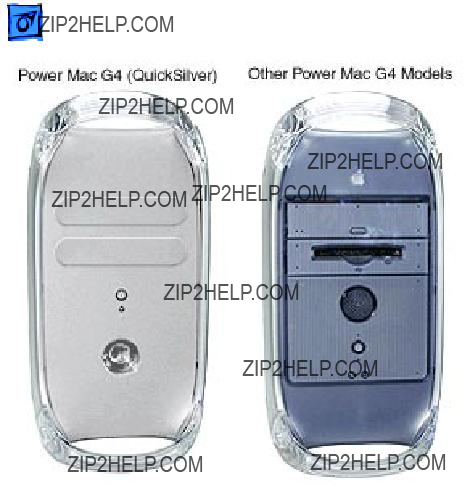
Identifying Versions of
the Power Mac G4
There are six models of
Power Mac G4 computers:
AGP Graphics, PCI Graphics,
Gigabit Ethernet, Digital
Audio, QuickSilver, and
QuickSilver 2002.
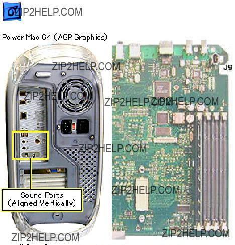
Power Mac G4 (QuickSilver and QuickSilver 2002) computers are easy to identify. Unlike other Power Mac G4 models, these models have a

To identify the other Power Mac G4 models, check the I/O panel at the back of the computer. The sound ports align horizontally in the lower half of the I/O panel on PCI Graphics models and vertically on AGP Graphics/ Gigabit Ethernet models. On Digital Audio models, the sound ports are in the upper half of the I/O panel. In addition, Digital Audio models include four expansion slots, instead of three slots on PCI/AGP Graphics/Gigabit Ethernet models.
To further distinguish Gigabit Ethernet models from AGP Graphics models, check the logic boards. AGP Graphics boards include an internal FireWire connector at J9; Gigabit Ethernet boards do not include the connector.
New Technologies
While the Power Mac G4 family of computers all use the innovative PowerPC G4 processor, they also include a range of other new hard- ware and architectures. For information on the latest technolgies, check the Apple Knowledge Base.

Features
Standard Con???gurations
Processor
???350 MHz,400 MHz, 450 MHz, 466 MHz, 500 MHz, 533 MHz, 733 MHz, 800 MHz, 867 MHz, 933 MHz, or 1 GHz PowerPC G4 processor; dual processors on some configurations
???Velocity Engine vector processing unit with 162 integrated Single Instruction Multiple Data (SIMD) instructions
???Full
???Powerful
???Data stream prefetching operations supporting four

simultaneous
???L2 or L3 cache
???
Memory
???64, 128, 256, or 512 MB of
64, 128, 256, or 512 MB of
???Four DIMM slots (PCI Graphics/AGP Graphics/Gigabit Ethernet) or three DIMM slots (QuickSilvers/Digital Audio)

Storage
???One of the following hard drives: 10, 13, 20, 27, 30, 40, 60, or 80 GB Ultra ATA
???One of the following optical drives:
???
???
???
???
???
???
???Optional 100 or 250 MB Zip drive
???Three
???One ATA drive preinstalled in standard configurations
???Support for up to two internal ATA drives
???Support for up to three internal SCSI drives

Graphics Support
???Video card installed in a dedicated graphics slot (either a PCI slot or an AGP slot)
???Support for up to 1,600 by 1,200 pixel resolution at 32 bits per pixel and up to
???
???ADC connector for digital
???Support for independent video output to two monitors (with NVIDIA TwinView video card)

Electrical Requirements and Agency Approvals
???Line voltage: 115V AC (90V to 132V AC) or 230V AC (180V to 264V AC)
???Frequency: 47 to 63 Hz, single phase
???Maximum continuous power (not including display): 200W EPA ENERGY STAR and Blue Angel compliant (some configurations)
Environmental Requirements
???Operating temperature: 50?? to 95?? F (10?? to 35?? C)
???Storage temperature:
???Relative humidity: 5% to 95% noncondensing
???Maximum altitude: 10,000 feet (3,048 m)
Size and Weight
???Height: 17.0 inches (43.2 cm)
???Width: 8.9 inches (22.6 cm)
???Depth: 18.4 inches (46.7 cm)
???Weight: 30.0 pounds (13.6 kg)
Note: Storage devices and interfaces vary among configurations.

The

Views
Power Mac G4 (AGP Graphics/Gigabit Ethernet) Views
FireWire Ports (2)
Ethernet Port
USB Ports (2)
Sound Input Port
Sound Output Port
Internal
Modem Port
(Optional)
VGA Monitor Port
(Slot 1: AGP)
Access Covers for
Expansion Slots
Power Mac G4 (Digital Audio) Views
Internal Modem Port
(Optional)
Headphone Jack
Digital Audio
Jack
CD or DVD Drive

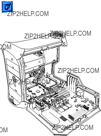
Power Mac G4 (AGP Graphics/Gigabit Ethernet) Internal Locator
Drive Bay 1
Drive Bay 2
Drive Bay 3
PCI Slots (3)


 AGP Slot


 SDRAM
SDRAM
Slots (4)
Power Mac G4 (QuickSilvers/Digital Audio) Internal Locator
Drive Bay 3
Drive Bay 2
Drive Bay 1
PCI Slots (4)
AGP Slot
SDRAM Slots (3)
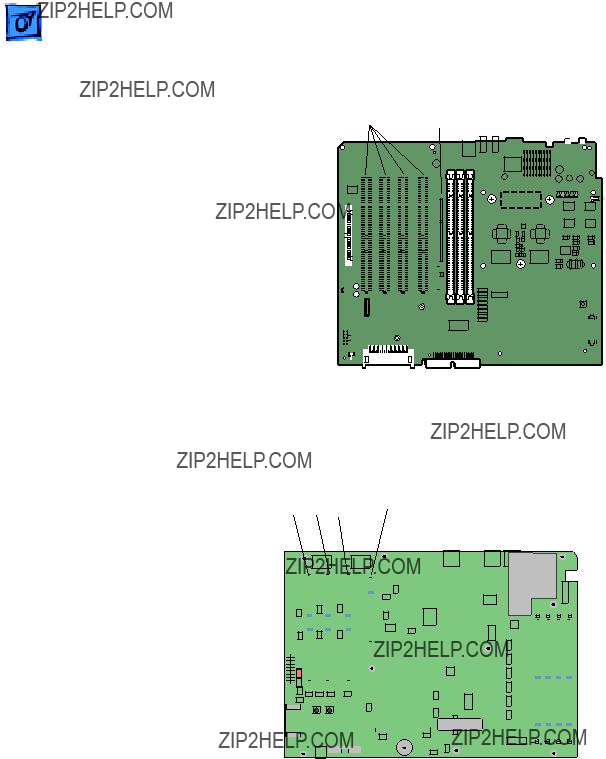
PowerMac G4 (AGP Graphics/Gigabit Ethernet) Logic Boards
PMU Button

Battery 

Ultra ATA 

Connector
Front Panel
Board
Speaker

AirPort IDE
Connector Connector
 Internal FireWire Port
(not included on Gigabit models)
PowerMac G4 (QuickSilvers/Digital Audio) Logic Board
USB
Ports
A & B
Ultra ATA 

Connector
Front Panel
Board
Speaker 

AirPortIDE
Connector Connector
Single or Dual  Processor
 PMU Button

 Battery
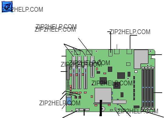
Power Mac G4 (PCI Graphics) Logic Board
J15 Ultra DMA/33
(ATA Drives)
J23 Power 


Ethernet Connector
 Firewire Ports (2)
Firewire Card


 Modem
Modem
Connector
SDRAM
DIMM Slots

Repair Strategy/Warranty
Strategy and Ordering
Service Power Mac G4 computers through module exchange and parts replacement.
Large businesses, universities, and

USA Ordering
U.S. service providers not enrolled in AppleOrder may fax their orders to Service Provider Support
Apple Computer, Inc.
Service Provider Support / MS
2323 Ridgepoint Drive
Austin, TX 78754
For U.S. inquiries, please call Service Provider Support (800 - 919 - 2775, option #1) .

Canadian Ordering
Canadian service providers not enrolled in ARIS may fax their orders to Service Provider Support in Canada (800-
Warranty
U.S. Only
Power Mac G4 computers are covered under the Apple One- Year Limited Warranty. The AppleCare Protection Plan is also available for these products. Service providers are reimbursed for warranty and AppleCare Protection Plan repairs. For pricing information, refer to Service Price Pages.
Canada Only
Power Mac G4 computers are covered under the Apple One- Year Limited Warranty. The AppleCare Protecion Plan is also available for these products. Service providers are reimbursed for warranty and AppleCare Protection Plan repairs. For pricing information, refer to Service Price Pages.

K Service Source
Take Apart
Power Mac G4 / Macintosh
Server G4
?? 2002 Apple Computer, Inc. All rights reserved.

General
Identifying Models of
the Power Mac G4
There are six models of Power Mac G4 computers: AGP Graphics, PCI Graphics, Gigabit Ethernet, Digital Audio, QuickSilver, and QuickSilver 2002.
Power Mac G4 (QuickSilver and QuickSilver 2002) computers are easy to identify. Unlike other Power Mac G4 models, these models


Tools
??? Flatblade screwdriver
??? Phillips screwdriver
??? Allen wrench (2.5 mm) to remove the power supply, side panels, top and rear handles, and front and rear supports
??? Jeweler???s screwdriver to remove the I/O panel cover and antenna
??? Needlenose pliers to remove the right and left side panels
??? ESD mat
Procedures
Opening the Computer
No preliminary steps are required before you begin this procedure.


Video Card
Before you begin, do the following:
??? Open the side access panel.
??? Remove the external video cable.
Note: The AGP video card is always installed in slot 1 (short slot). The DVD decoder module is used only in Power Mac G4 (PCI Graphics) computers.

Replacement Note: If the replacement card does not have a fence already installed, attach the fence enclosed in the box. Using a Phillips screwdriver, install the two small Phillips screws on either side of the ADC connector and the two large Phillips screws on the fence side tabs. Using pliers, install the two

 Take Apart Modem, AGP Graphics/Gigabit Ethernet/Digital Audio/QuickSilvers - 10
Modem, AGP
Graphics/Gigabit
Ethernet/Digital Audio/
QuickSilvers
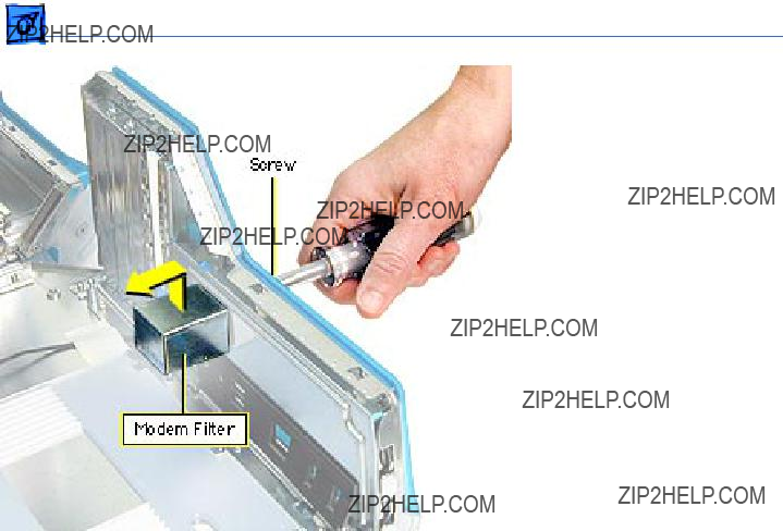
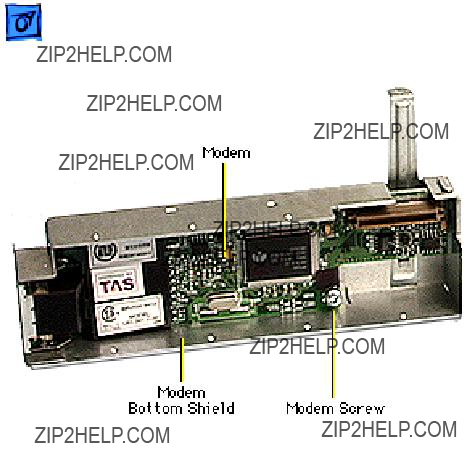
Note: The Power Mac G4 (AGP Graphics/Gigabit Ethernet/Digital Audio/ QuickSilver/QuickSilver 2002) modem requires a modem filter; the two are separate parts. To remove the modem, you do not need to remove the modem filter.
Before you begin, open the side access panel.

Take Apart Modem, AGP Graphics/Gigabit Ethernet/Digital Audio/QuickSilvers - 11
Warning: Use care when disconnecting or connecting the modem to the J27 connector on the logic board. Bent pins in the J27 connector could cause a short in the logic board.
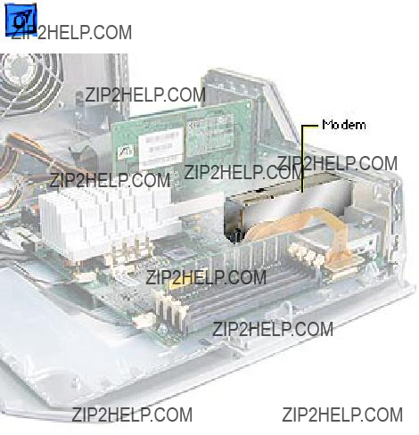
1. Remove the two modem mounting screws.
2. Lift the modem straight up to disconnect it from the logic board.
Take Apart Modem, AGP Graphics/Gigabit Ethernet/Digital Audio/QuickSilvers - 12
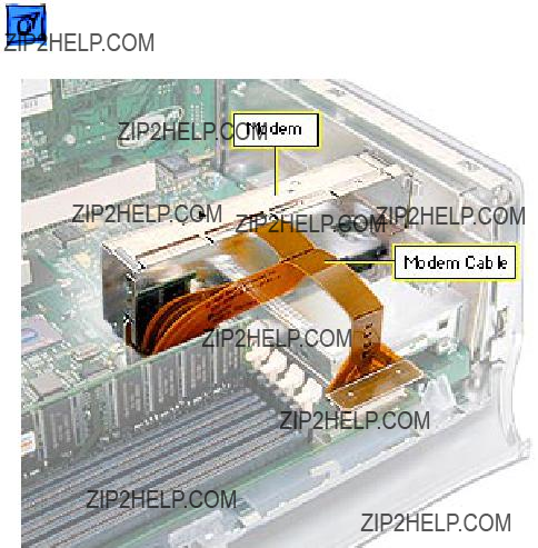
3. Disconnect the modem filter cable from the modem.
4. Remove the modem from the computer.
Replacement Note: After replacing an international modem, use the Modem Country Selector utility to set the modem to the correct country.

 Take Apart Modem Filter, AGP Graphics/Gigabit Ethernet/Digital Audio/QuickSilvers
Modem Filter, AGP
Graphics/Gigabit
Ethernet/Digital Audio/
QuickSilvers
Before you begin, do the following:
??? Open the side access panel.
??? Remove the logic board.
Take Apart Modem Filter, AGP Graphics/Gigabit Ethernet/Digital Audio/QuickSilvers
1. Remove the screw that secures the modem filter to the I/O panel.
Take Apart Modem Filter, AGP Graphics/Gigabit Ethernet/Digital Audio/QuickSilvers
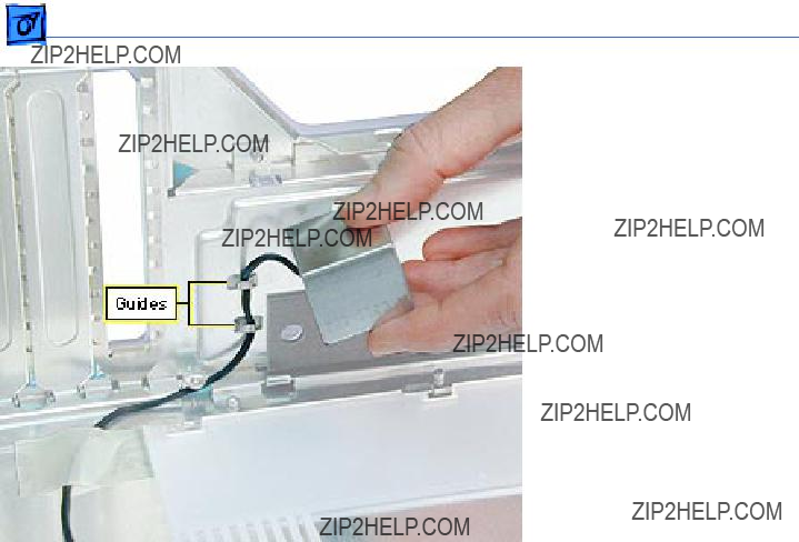
2. Free the modem filter cable from the chassis guides and remove the modem filter from the computer.
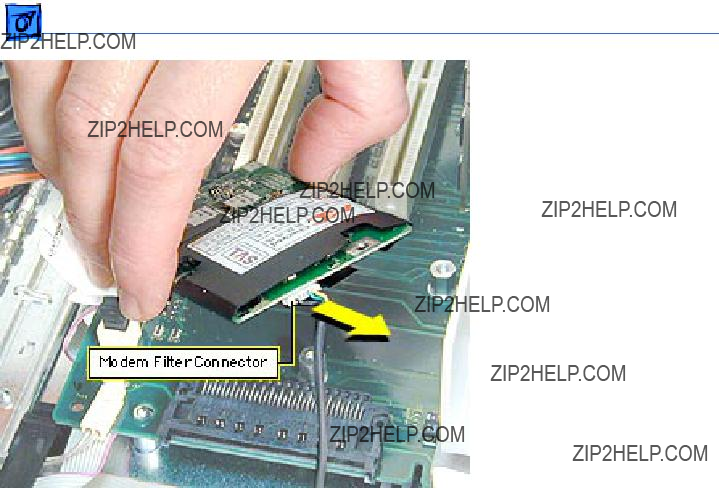
Modem, PCI Graphics
Before you begin, open the side access panel.
Warning: Use care when disconnecting or connecting the modem to the J27 connector on the logic board. Bent pins in the J27 connector could cause a short in the logic board.

2. Remove the screw that secures the modem leg standoff to the logic board.
4. Gently lift up the modem to remove it from the logic board.
Note: If you are replacing the modem, continue with the Take Apart procedures to remove the modem from the bottom modem shield.


Replacement Note: After replacing an international modem, use the Modem Country Selector utility to set the modem to the correct country.

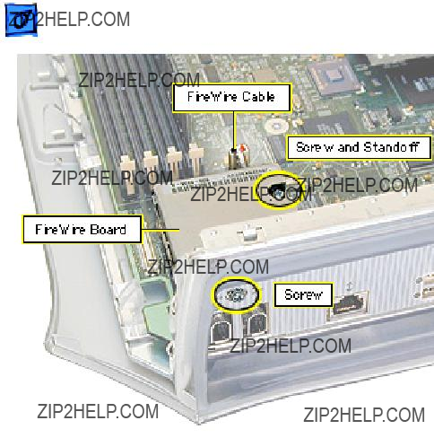
FireWire Board, PCI
Graphics
Note: The FireWire board is used only in Power Mac G4 (PCI Graphics) computers. Power Mac G4 (AGP Graphics/Gigabit Ethernet/ Digital Audio/QuickSilver/ QuickSilver 2002) computers have FireWire built into the logic board.
Before you begin, do the following:
??? Open the side access panel.
??? Remove the modem.
Processor Fan, Power
Mac G4 (QuickSilvers)
Before you begin, open the side access panel.

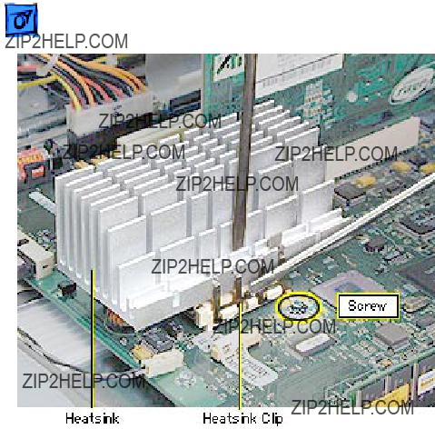
Processor Module, Power Mac G4 (QuickSilvers)
Before you begin, do the following:
??? Open the side access panel.
??? Remove the processor fan.
??Warning: The heatsink covering the processor may be hot. If the computer has been recently operating, allow it to cool down before performing this procedure.


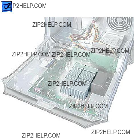
Processor Module,
AGP Graphics/Gigabit
Ethernet/Digital Audio
Before you begin, open the side access panel.
??Warning: The heatsink covering the processor may be hot. If the computer has been recently operating, allow it to cool down before performing this procedure.


??Warning: Hold the module as shown when removing or installing it to avoid bending the processor connector pins.

Processor Module, PCI
Graphics
Before you begin, open the side access panel.
Note: The Power Mac G4 (PCI Graphics) processor requires a jumper installed at J25 on the logic board.


 Take ApartLogic Board, Power Mac G4 (QuickSilvers) - 47
Logic Board, Power
Mac G4 (QuickSilvers)
Before you begin, open the side access panel and remove the following:
??? video card
??? processor fan
??? processor module
??? PCI cards (if present)
??? modem (if present)
??? AirPort card (if present)
??Warning: Be sure to reinstall the heatsink after completing this procedure. Operating the computer without the heatsink in place


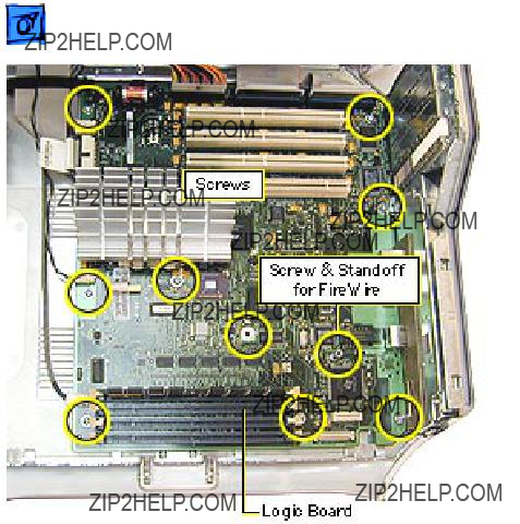
 Take Apart Logic Board, AGP Graphics/Gigabit Ethernet/Digital Audio - 50
Logic Board, AGP
Graphics/Gigabit
Ethernet/Digital Audio
Before you begin, open the side access panel and remove the following:
??? video card
??? processor module
??? PCI cards (if present)
??? modem (if present)
??? AirPort card (if present)
Note: While the layout of the Power Mac G4 (Digital Audio) logic board differs from the logic board layout in the illustrations for this

3. For Power Mac G4 (Gigabit Ethernet/ Digital Audio) computers, remove the three processor module standoffs.


 Take ApartLogic Board, PCI Graphics - 53
Logic Board, PCI
Graphics
Before you begin, open the side access panel and remove the following:
??? video card
??? PCI cards (if present)
??? modem (if present)
??? FireWire board


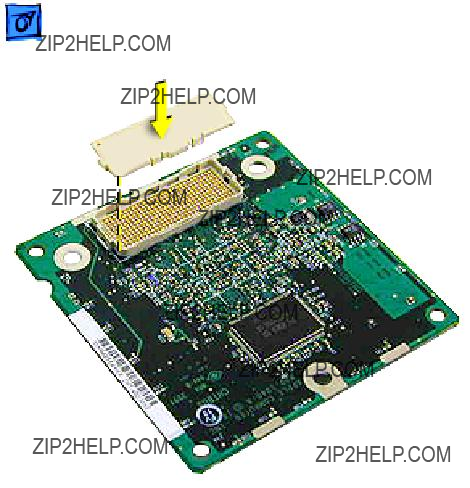
SDRAM DIMM
Before you begin, open the side access panel.

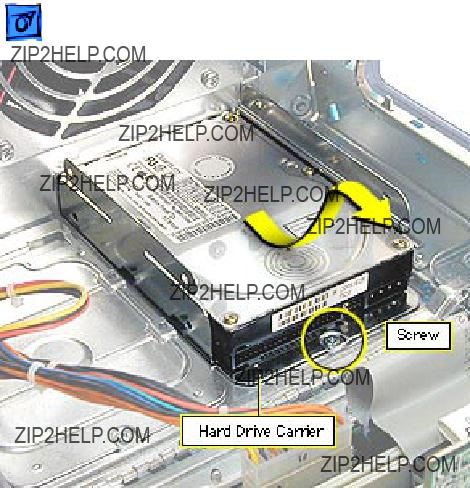
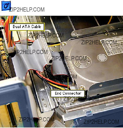
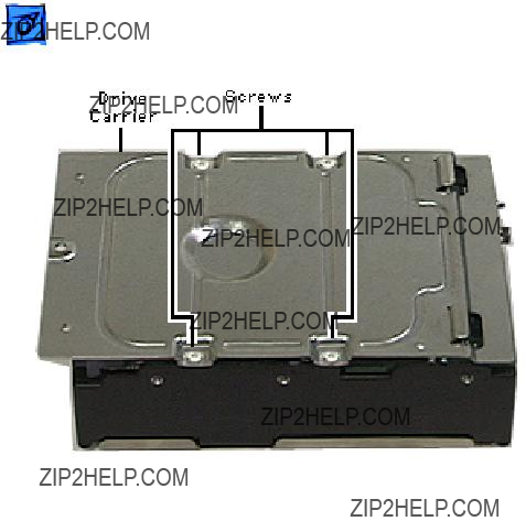
Hard Drive, IDE /ATA
Before you begin, open the side access panel.
Note: The Power Mac G4 supports a total of three internal hard drives. It can accommodate up to two Ultra ATA drives in drive bay 3, near the rear of the computer. ATA drives are not supported in drive bay 1 or 2.
Note: You must assign a SCSI ID number to every additional hard drive and the number must not conflict


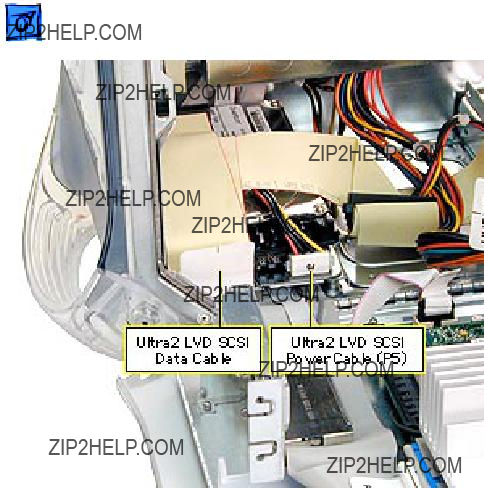
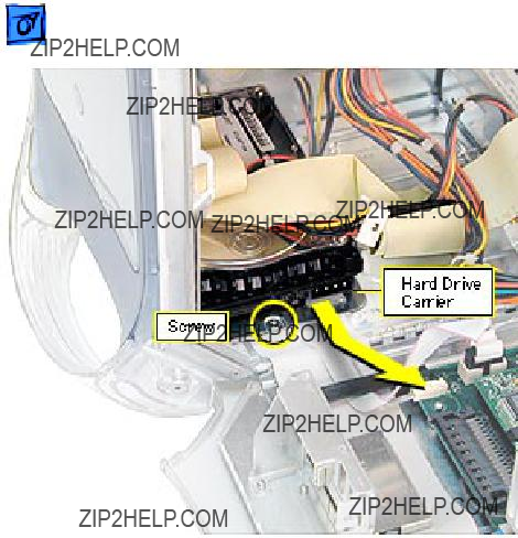
Hard Drive, Ultra2
LVD SCSI
Before you begin, open the right side access panel.
Note: This computer supports a total of three internal hard drives. If a unit has at least one internal Ultra2 LVD SCSI drive, an Ultra2 LVD SCSI PCI card, and a SCSI data cable, you can connect additional internal and external Ultra2 LVD SCSI devices. The unit???s SCSI data cable supports three internal SCSI drives;


Ultra2 LVD SCSI Card
Before you begin, open the side access panel.

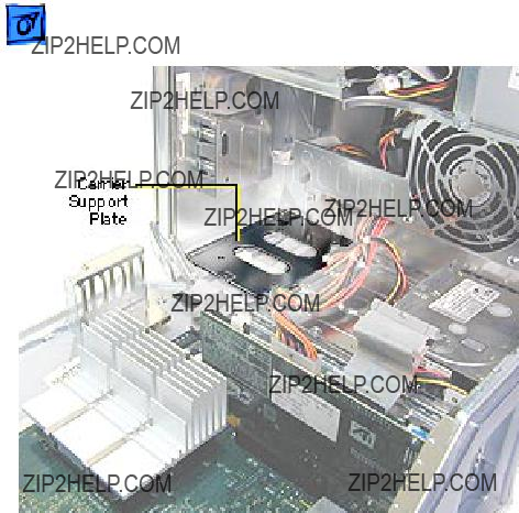
Carrier Support Plate
Note: Perform this procedure only if you must replace the support plate or the cables below the plate.
Before you begin, do the following:
??? Open the side access panel.
??? Remove the hard drive carrier in drive bay 1.


CD/DVD Drive, Power
Mac G4 (QuickSilvers)
Before you begin, open the side access panel.
Note: You remove the drive carrier from the computer with the drives attached to the carrier.


5. Remove the carrier and drives from the computer.


Zip Bezel/Blank Bezel, Power Mac G4 (QuickSilvers)
Before you begin, open the side access panel.

Zip Drive, Power Mac
G4 (QuickSilvers)
Before you begin, open the side access panel.
Note: You remove the drive carrier from the computer with the drives attached to the carrier.


5. Remove the carrier and drives from the computer.


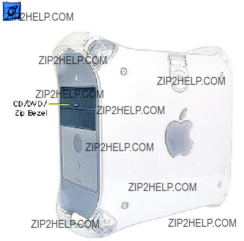
CD/DVD Bezel, PCI/
AGP Graphics/Gigabit
Ethernet/Digital Audio
Before you begin, open the side access panel.


CD/DVD Drive, PCI/
AGP Graphics/Gigabit
Ethernet/Digital Audio
Before you begin, do the following:
??? Open the side access panel.
??? Remove the CD/DVD drive bezel.


Take Apart CD/DVD Drive, PCI/AGP Graphics/Gigabit Ethernet/Digital Audio - 100
6. Continue sliding the drive carrier out of the computer. Important:
The drive carrier may be difficult to push forward due to the EMI gasket and tape located on the underside of the carrier (directly below the Zip drive).
7. When the carrier is out of the computer, remove the EMI shield from the back of the
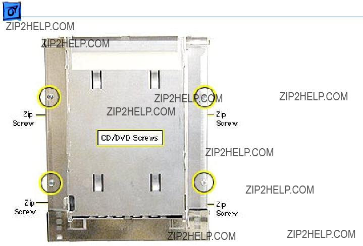
Take Apart CD/DVD Drive, PCI/AGP Graphics/Gigabit Ethernet/Digital Audio - 101
Note: Perform the following procedure if you are replacing the
8. Using a Phillips screwdriver, remove the drive carrier mounting screws.
9. Slide the drive(s) out of the carrier.
Replacement Note: The

Take Apart CD/DVD Drive, PCI/AGP Graphics/Gigabit Ethernet/Digital Audio - 102
drive back into the carrier, lift the back of the drive slightly so that the drive is flush against the carrier.
Replacement Note: When inserting the drive carrier into the computer, make sure the carrier tab slides into the hole on the stationary drive shelf.

Zip Drive, PCI/AGP
Graphics/Gigabit
Ethernet/Digital Audio
If removing the Zip drive, follow the procedures for removing the CD/DVD Drive.
Important: After you remove the screws mounting the Zip/CD/DVD carrier to the chassis, the carrier may be difficult to push forward due to EMI tape on the carrier???s underside holding it in place. Continue pushing forward until the carrier is released.

Fan, Power Mac G4 (QuickSilvers)
Before you begin, open the side access panel.


Fan, PCI Graphics,
AGP Graphics/Gigabit
Ethernet/Digital Audio
Before you begin, open the side access panel.


Power Supply, Power
Mac G4 (QuickSilvers)
Before you begin, do the following:
??? Open the side access panel.
??? Remove the CD/DVD/Zip
drive carrier.


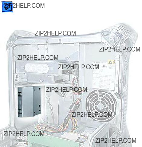
 Take Apart Power Supply, PCI/AGP Graphics/Gigabit Ethernet/Digital Audio - 122
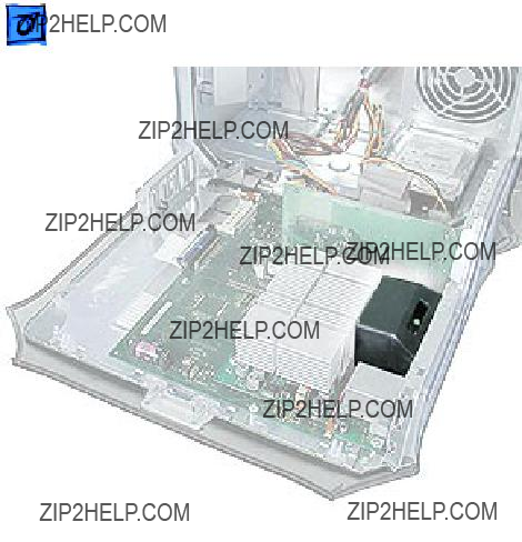
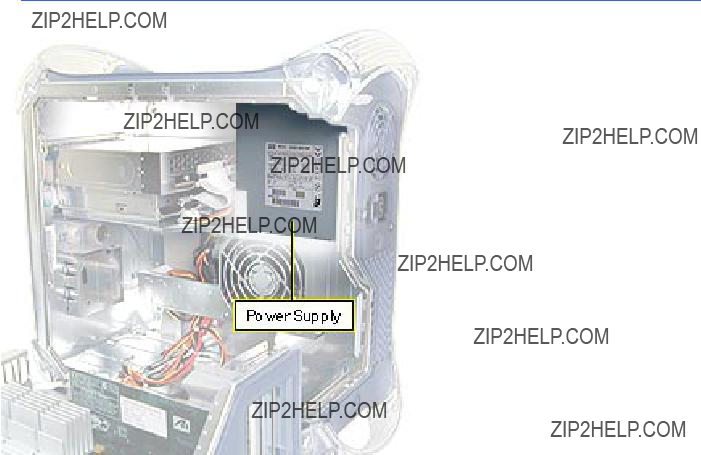
Power Supply, PCI/
AGP Graphics/Gigabit
Ethernet/Digital Audio
Before you begin, do the following:
??? Open the side access panel.
??? Remove the CD/DVD drive bezel.
??? Move the CD/DVD/Zip drive carrier forward 1 inch.
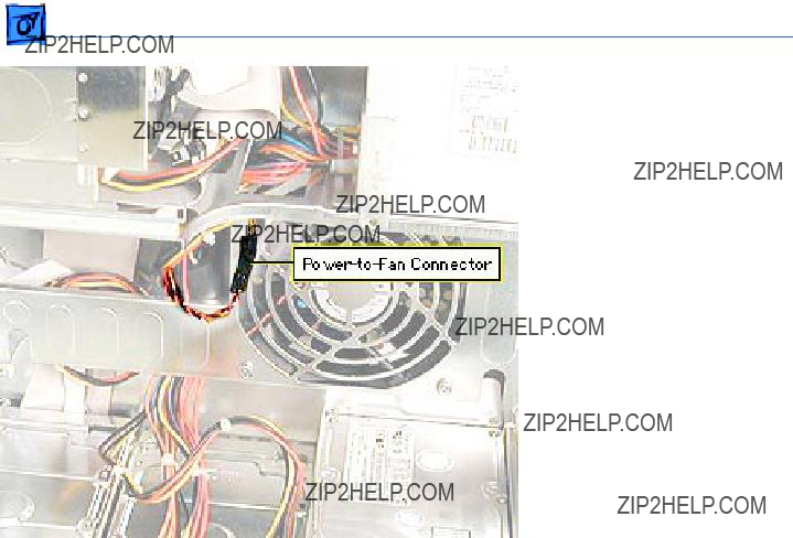
Take Apart Power Supply, PCI/AGP Graphics/Gigabit Ethernet/Digital Audio - 123
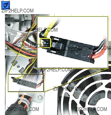
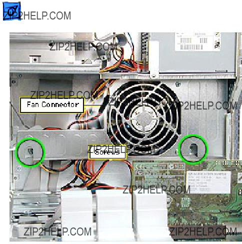
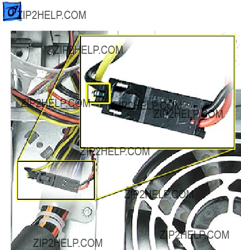
1. Disconnect the power-
Take Apart Power Supply, PCI/AGP Graphics/Gigabit Ethernet/Digital Audio - 124
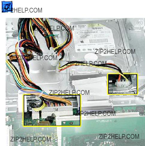
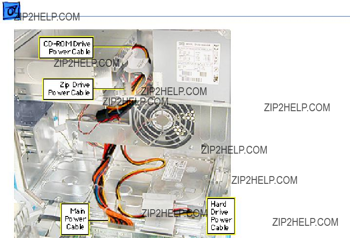
2. Disconnect the following power cables:
???cables P6 and P7 from the
???Power Mac G4 (PCI Graphics): cable P4 from the front panel board
???main power cable from the logic board
???cable(s) to hard drives
Take Apart Power Supply, PCI/AGP Graphics/Gigabit Ethernet/Digital Audio - 125
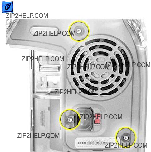
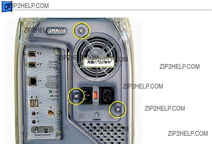
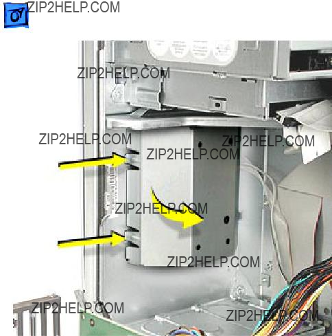
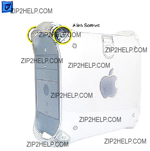
3. Using a 2.5 mm Allen wrench, remove the three screws on the rear vented panel.
Take Apart Power Supply, PCI/AGP Graphics/Gigabit Ethernet/Digital Audio - 126
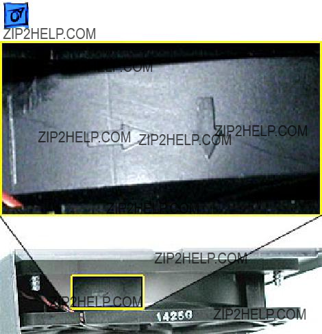
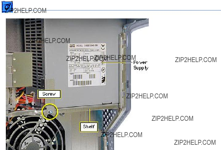
4. On the inside of the chassis, remove the screw that attaches the power supply to the power supply shelf.
5. Slide the power supply forward toward the front of the computer. Maneuver the power supply (clearing the security bar on the inside and upper chassis) and its cables out of the chassis.
Note: If you are replacing the power supply, remove the power supply bracket

Take Apart Power Supply, PCI/AGP Graphics/Gigabit Ethernet/Digital Audio - 127
and reattach it to the new power supply.
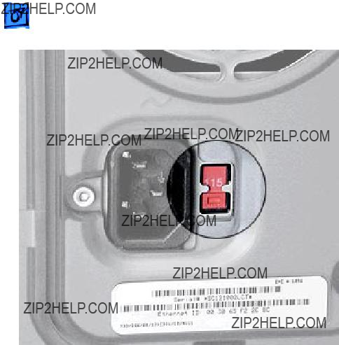
Replacement Note: You must set the power supply voltage switch to the correct setting (115 V in the U.S.) to avoid damaging the computer.

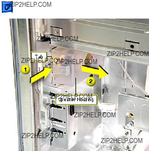
Speaker, Power Mac
G4 (QuickSilvers)
Before you begin, do the following:
??? Open the side access panel.
??? Remove the carrier support plate.


Speaker, PCI/AGP
Graphics/Gigabit
Ethernet/Digital Audio
Before you begin, do the following:
??? Open the side access panel.
??? Remove the carrier support plate.
Front Panel Board, Power Mac G4 (QuickSilvers)
Before you begin, open the side access panel.


Front Panel Board,
PCI/AGP Graphics/
Gigabit Ethernet/
Digital Audio
Before you begin, open the side access panel.


 Take ApartAntenna - 140
Antenna
Note: The antenna is routed through the chassis in two ways: under the logic board and through drive bay 1. Do not remove or replace the antenna if it is routed under the logic board. To replace this type of antenna, you must replace the entire chassis.
Before you begin, remove the following:
??? top front handle
??? top panel
??? carrier support plate (if

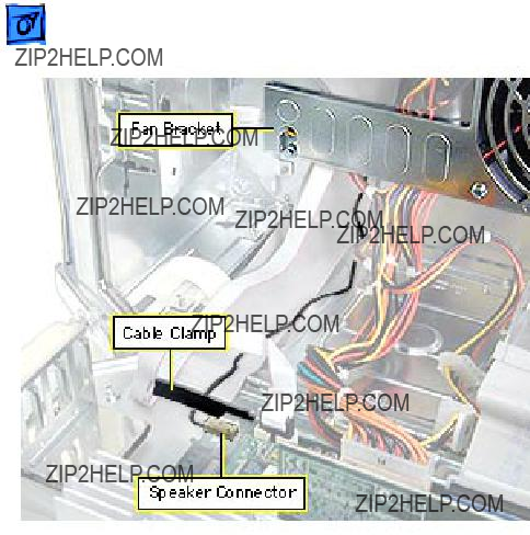
2. Free the antenna cable from the cable clamp and the fan bracket.


Top Handles, Front
and Rear
No preliminary steps are required before you begin this procedure.


Top Panel
Before you begin, remove the following:
??? top front handle
??? top rear handle

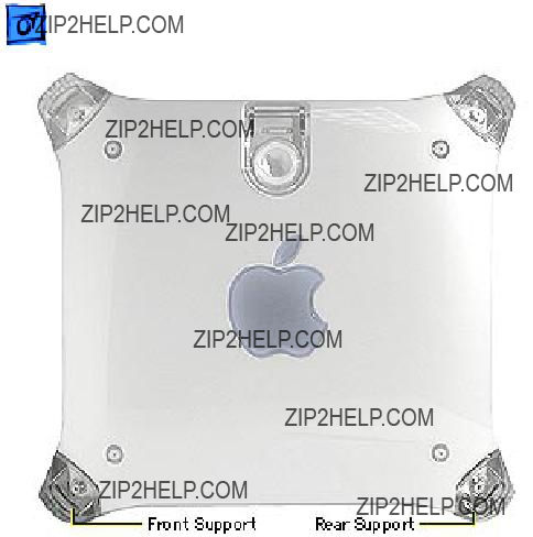
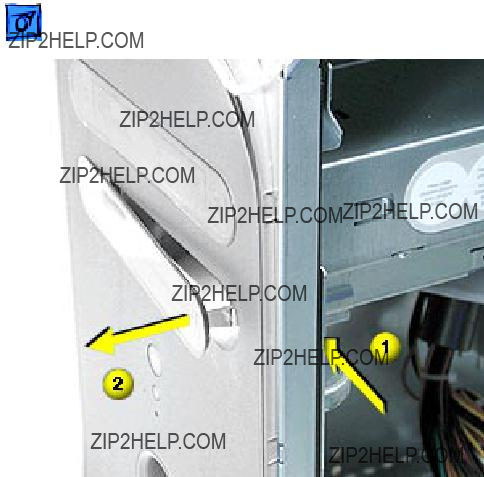
Supports, Front and
Rear
Before you begin, place the computer on an ESD mat and turn the unit upside down.
??Warning: When the computer is upside down or the lower supports are removed, the computer can be unstable.
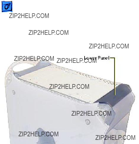
Lower Panels, Front
and Rear
Before you begin, remove the front and/or rear support.
??Warning: When the computer is upside down or the lower supports are removed, the computer can be unstable.

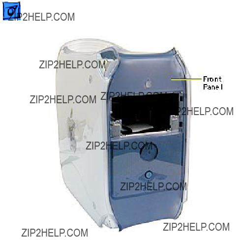
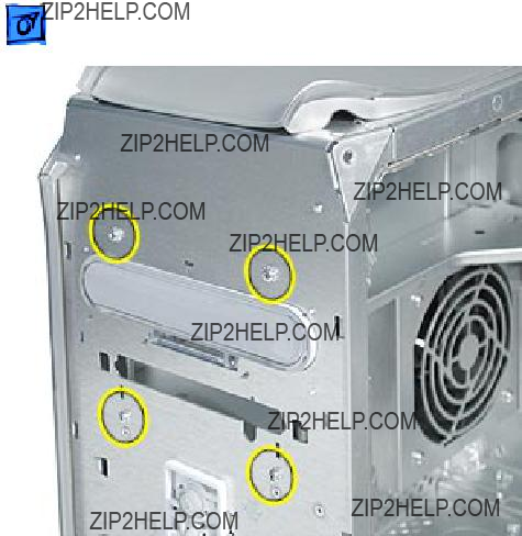
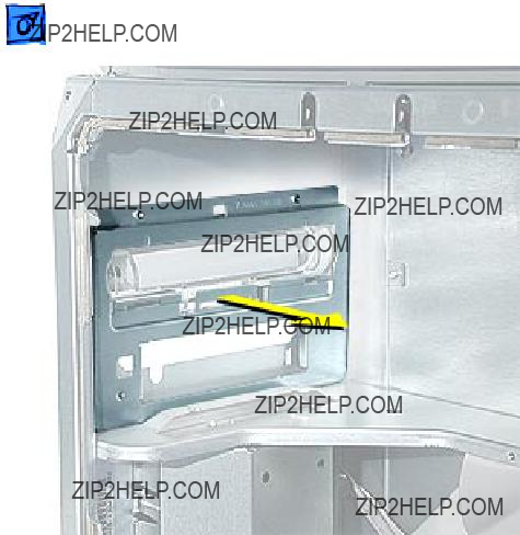
Front Panel
Before you begin, remove:
??? top front handle
??? lower front support and lower front panel
??? Power Mac G4 (PCI/AGP Graphics/GIgabit Ethernet/Digital Audio): CD/DVD drive bezel and CD/DVD drive carrier
??? Power Mac G4 (QuickSilvers): CD/DVD/ Zip drive carrier
??Warning: When the lower support is removed, the computer can be unstable.

Note: If you are installing a new front panel on Power Mac G4 (QuickSilvers), transfer the blank or Zip bezel from the original panel to the new panel.

 Take ApartCD/DVD Drive Door, Power Mac G4 (QuickSilvers) - 154
CD/DVD Drive Door, Power Mac G4 (QuickSilvers)
Before you begin, remove:
??? top front handle
??? lower front support and lower front panel
??? CD/DVD/Zip drive carrier
??? front panel
??Warning: When the lower support is removed, the computer can be unstable.


Rear Vented Panel
Before you begin, remove the following:
??? top rear handle
??? lower rear support
??Warning: When the lower support is removed, the computer can be unstable.


 Take ApartLatch Panel - 161
Latch Panel
Before you begin, remove the following:
??? video card
??? PCI cards (if present)
??? Power Mac G4 (PCI Graphics): FireWire board (if present)
??? Power Mac G4 (PCI Graphics): modem (if present)
??? AirPort card (if present)
??? logic board

 Take ApartRight Side Access Panel - 163
Right Side Access
Panel
Before you begin, remove the following:
??? PCI cards (if present)
??? video card
??? FireWire board (if present)
??? modem (if present)
??? AirPort card (if present)
??? logic board


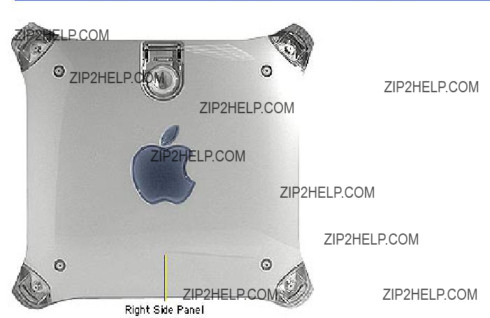
Left Side Panel
No preliminary steps are required before you begin this procedure.


I/O Panel, PCI
Graphics
Note: The I/O panel can be removed only in Power Mac G4 (PCI Graphics) computers. The I/O panel in Power Mac G4 (AGP Graphics/Gigabit Ethernet/ Digital Audio/QuickSilver/ QuickSilver 2002) is part of the chassis.
Before you begin, do the following:
??? Open the side access panel.
??? Remove the logic board.


I/O Panel Cover
Before you begin, do the following:
??? Open the side access panel.
??? Remove the logic board.
??? Power Mac G4 (PCI Graphics): Remove the I/O panel.
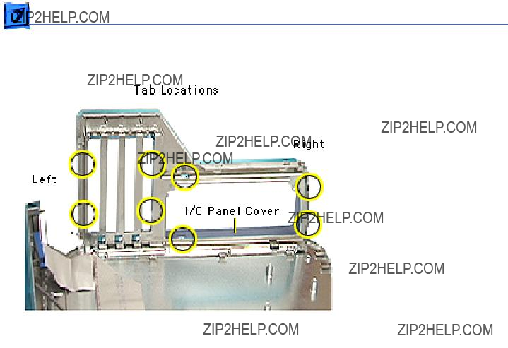
Take ApartI/O Panel Cover - 175
Note: Because the I/O panel cover can be difficult to remove, take your time prying up the plastic tabs.
1. Using a jeweler???s screwdriver and working from right to left, carefully pry the plastic tabs away from the metal frame. As each tab is released, pull the I/O cover away from the frame.
2. Remove the I/O panel cover from the chassis.

K Service Source
Troubleshooting
Power Mac G4/
Macintosh Server G4
?? 2002 Apple Computer, Inc. All rights reserved.

General
Block Diagrams
Power Mac G4 (QuickSilvers/Digital Audio) Block Diagram
Processor Module
Ethernet port
Firewire port
Firewire port
USB port A
USB port B
Headphone jack
Apple speaker

Power Mac G4 (Gigabit Ethernet) Block Diagram
Power Mac G4 (AGP Graphics) Block Diagram
Firewire port Firewire port
Ethernet port
USB port A
USB port B
Microphone jack Headphone jack

Power Macintosh G4 (PCI Graphics) Block Diagram

There is a
Power Mac G4 (all models except PCI Graphics):
???1 Beep: No RAM is installed or detected.
???2 Beeps: Incompatible RAM types are installed (for example, both SDRAM and EDO installed).
???3 Beeps: No RAM banks passed memory testing.
???4 Beeps: No good boot images are detected in the boot ROM (and/or there is a bad sys config block).
???5 Beeps: The processor is not usable.

Power Macintosh G4 (PCI Graphics):
???1 Beep: No RAM is installed or detected.
???2 Beeps: Incompatible RAM types are installed (for example, both SDRAM and EDO installed).
???3 Beeps: No RAM banks passed memory testing.
???4 or 5 Beeps: Bad checksum for the remainder of the boot ROM block. The ROM is bad and probably cannot be fixed.
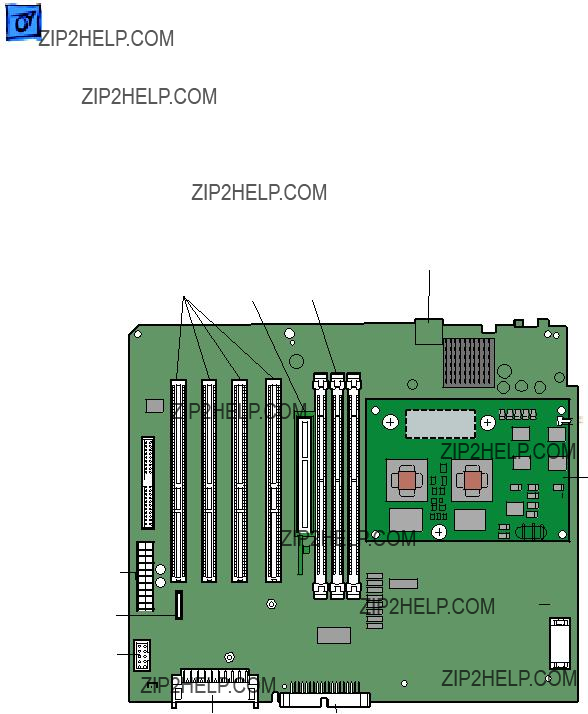
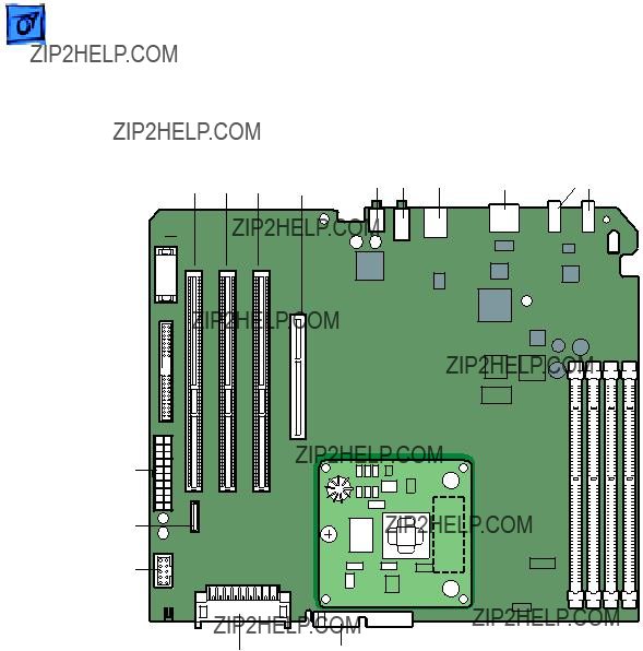
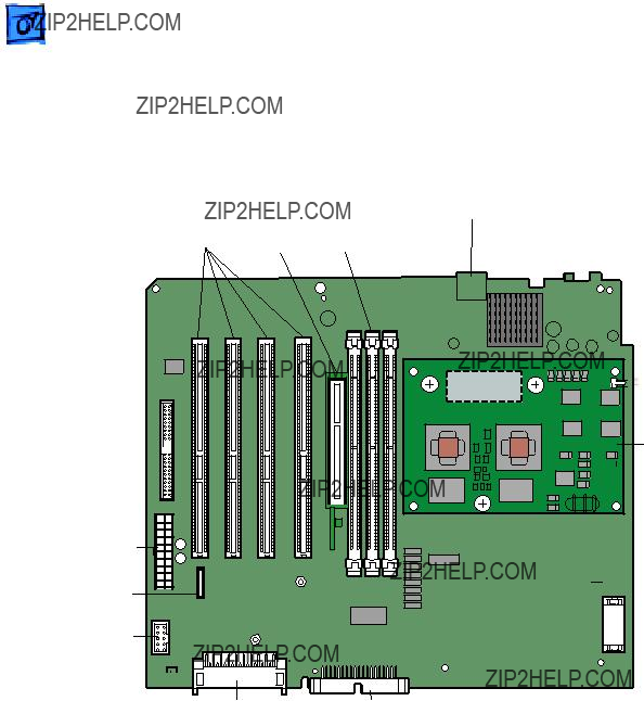
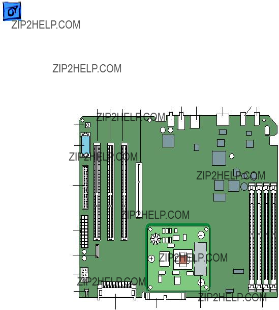
Logic Board Diagrams
Power Mac G4 (QuickSilvers/Digital Audio)
Logic Board Diagram
USB
Ports
A & B
Ultra ATA 

Connector
Front Panel
Board
Speaker 

AirPortIDE
Connector Connector
Single or Dual  Processor
 PMU Button

 Battery
Power Mac G4 (AGP Graphics/Gigabit Ethernet)
Logic Board Diagram
AirPort IDE
Connector Connector
A & B Connector
Processor
Slot
FireWire
Ports (2)
 Internal FireWire Port
(not included on Gigabit models)
SDRAM
DIMM Slots


Logic Board Troubleshooting
Power Mac G4 (all models except PCI Graphics)
Processor Module
The logic board comes with a removable processor module. The processor should rarely fail and should be replaced only as a last resort. Processor modules can be ordered from Service.
Refer to ???Processor Module??? in the Take Apart chapter for more information.
Resetting the PMU on the Logic Board
The PMU (Power Management Unit) is a microcontroller chip that controls all power functions for the computer. The PMU is a computer within a computer. It has memory, software, firmware,

I/O, two crystals, and a CPU. Its function is to:
???Tell the computer to turn on, turn off, sleep, wake, idle, etc.
???Manage system resets from various commands.
???Maintain parameter RAM (PRAM).
???Manage the
Important: Be very careful when handling the main logic board. Remove the battery when handling the logic board so the PMU is not affected. The PMU is very sensitive and touching the circuitry on the logic board can cause the PMU to crash. If the PMU crashes, the battery life goes from about five years to about two days if the PMU is not reset. The PMU chip is located on the underside of the logic board at U20; refer to the Power Mac G4 (AGP Graphics/ Gigabit Ethernet/Digital Audio) Logic Board Diagrams for the location of the PMU button.
Many system problems can be resolved by resetting the PMU chip.
Whenever you have a unit that fails to power up, follow this

procedure before replacing any modules:
1.Disconnect the power cord and check the battery in the battery holder (BT1). The battery should read 3.3 to 3.7 volts. If the battery is bad, replace the battery, wait ten seconds, and then reset the PMU (refer to the next step). If the battery is good, go to the next step.
2.Press the PMU reset switch (S1) once on the logic board and then proceed to step 3. Do NOT press the PMU reset switch a second time because it could crash the PMU chip.
3.WAIT ten seconds before connecting the power cord and powering the computer on. If the computer powers on, go to the next step. If the computer does not power on, there is something else wrong with the computer; refer to the symptom/cure chart, ???Startup??? in this chapter.
4.Run Apple Hardware Test and return the computer to the customer.
Note: This entire procedure resets the computer???s PRAM. Be sure to reset the computer???s time, date, and other system parameter settings before returning the computer to the customer.
Logic Board LEDs: Power Mac G4 (all models except PCI
Graphics)
There is one red LED on the Power Mac G4 (AGP Graphics/Gigabit Ethernet/Digital Audio/QuickSilver/QuickSilver 2002) logic boards. It indicates that there is power to the board and does not imply a fault condition. Hardware such as DIMMs and PCI cards should not be installed or removed when the LED is on.

Power Macintosh G4 (PCI Graphics)
Processor Module
The logic board comes with a removable processor module. The processor should rarely fail and should be replaced only as a last resort. Processor modules can be ordered from Service.
Note that when you replace the logic board on a Power Macintosh G4 (PCI Graphics), you must also change the processor jumper block and warranty sticker to be compatible with the processor module. Failure to install the jumper block properly will result in a unit that does not boot up. No jumper block is required for Power Mac G4 (AGP Graphics/Gigabit Ethernet/Digital Audio) processors.
Refer to ???Processor Module??? in the Take Apart chapter for more information.

Resetting the Cuda Chip: Power Macintosh G4 (PCI
Graphics)
The Cuda is a microcontroller chip on the Power Macintosh G4 (PCI Graphics) logic board. Its function is to
???Turn system power on and off.
???Manage system resets from various commands.
???Maintain parameter RAM (PRAM).
???Manage the
Many system problems can be resolved by resetting the Cuda chip (see the Symptom Charts for examples). Press the Cuda reset button on the logic board to reset the Cuda chip. The Cuda reset button is located on the logic board to the right of the battery. Refer to the Logic Board Diagram earlier in this chapter for location information. If you continue to experience system problems, refer to ???Resetting the PCI Logic Board??? in this chapter.

Resetting the PCI Logic Board
Resetting the logic board can resolve many system problems (see the Symptom/Cure tables for examples). Whenever you have a Power Macintosh G4 (PCI Graphics) computer that fails to power up, you should follow this procedure before replacing any modules.
1.Unplug the computer.
2.Press the Power On button on the front of the unit.
3.Open the side access panel.
4.Remove the battery from the logic board.
5.Wait at least 10 minutes before replacing the battery.
6.Make sure the battery is installed in the correct +/- direction.
7.Reassemble the computer and test the unit.

Note: This procedure resets the computer???s PRAM. Be sure to check the computer???s time/date and other system parameter settings afterwards.
Logic Board LEDs: Power Macintosh G4 (PCI Graphics)
There are seven diagnostic LEDs on the Power Mac G4 (PCI
Graphics) logic board. A graphic follows showing their location.
DS1 = ATA drive activity
If a CD and/or Zip are attached to the ATA bus, this LED will illuminate at power/on restart time for a few seconds. After that, it is unlikely it will illuminate again in a

DS4 and DS5 = USB power for downstream devices
DS5 = USB port 1- lower
DS4 = USB port 2- upper
(There is no DS2 or DS3 on the board.)
When illuminated, these LEDs indicate that the computer is providing power (+5 V) to downstream USB ports. USB devices do not need to be connected in order for these LEDs to illuminate. However, if one or both of the LEDs is not illuminated and a USB device is/was attached (and the system has completed its boot process), then the logic board has removed downstream power because of a trouble condition.
Since the downstream power is controlled individually for each port, it is possible to have these LEDs in a different state: one off and one on. This way if one port has troubled USB devices, the

other port can still be functional. These LEDs are not immediately illuminated at the beginning of a restart or cold
1.Unit is powered on and other LEDs will illuminate while DS4 and DS5 are off.
2.Then DS4 and DS5 on for a second or two
3.Then off very briefly (1 second)
4.Then back on (confirms secondary PCI bus is initialized and power now available)
These two LEDs are often useful when troubleshooting an unpredictable system. If they stay on (step 4) then the secondary PCI bus has been initialized which happens relatively late in the boot/hardware initializing process.

DS6 = Ultra ATA bus activity
DS6 indicates Ultra ATA bus activity.
DS7 & DS8 = Power Indication
In a working unit, these LEDs should be in sync with each other: both on or both off. If one LED is on and the other is off, there is a problem.
DS9 = CPU Bus Request
When illuminated, this LED indicates that the CPU is requesting the bus. This LED will rarely glow as brightly as the others (like the Ultra ATA LED) given that the CPU is not always requesting the bus, and when it does, the period of time is short. As a result, you may need to watch this LED much more carefully than the others to tell if there is activity. If this LED is ever on continuously and bright, then the system is troubled and likely hung.

Power Macintosh G4 (PCI Graphics) LEDs Locator
DS8 
DS9

Power Supply Veri???cation
To start up, the Power Mac G4 logic board requires a ???trickle??? power of +5V for AGP and PCI models, +28V for Gigabit Ethernet/ Digital Audio models, or +25V for QuickSilver models. If the system fails to start up, follow the procedure outlined below to determine whether the problem is related to the power supply.
Note: To verify the power supply, you need a volt meter.
Veri???cation Procedure
Follow the procedures in the Take Apart chapter to access the power supply.
Important: For this verification procedure when connecting the volt meter leads to specific pins, ensure the power supply cable remains securely plugged into the power supply connector on the logic board.
1.Plug in a
2.Power Mac G4 (AGP or PCI) (see Figure 1):
Connect the black lead of the volt meter to pin 16 of the 20- pin power supply connector. Connect the red lead of the volt meter to pin 9 of the power supply connector. The volt meter should measure approximately +5V.
If you do not get a reading of +5V,
If you do measure +5V on pin 9, the power supply is likely OK. Go to the next step for further verification.
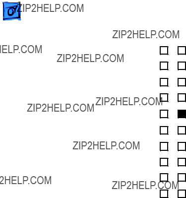
Figure 1. Power Supply

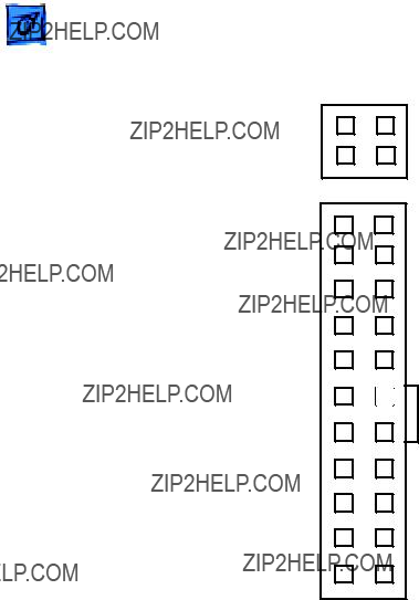
3.Power Mac G4 (Gigabit Ethernet/Digital Audio) (see Figure 2 ) :
Connect the black lead of the volt meter to pin 11 of the 22- pin power supply connector. Connect the red lead of the volt meter to pin 22 of the power supply connector. The volt meter should measure approximately +28V.
If you do not get a reading of +28V,
If you do measure +28V on pin 22, the power supply is likely OK. Go to the next step for further verification.

GND Pin 11 +12V Pin 10 NC Pin 9 +3.3VPin 8 GND Pin 7 +5V Pin 6 GND Pin 5 +5V Pin 4 GND Pin 3 +3.3V Pin 2
+3.3VPin 1
Pin 22+28V TRKL
Pin 21+5V
Pin 20+5V
Pin 19GND
Pin 18GND
Pin 17GND
Pin 16GND
Pin 15[Power On] Pin 14GND
Pin
Pin 12+3.3V
Figure 2. Power Supply

4.Power Mac G4 (QuickSilver/QuickSilver 2002) (see Figure 3):
Connect the black lead of the volt meter to pin 11 of the 22- pin power supply connector. Connect the red lead of the volt meter to pin 22 of the power supply connector. The volt meter should measure approximately +25V.
If you do not get a reading of +25V,
If you do measure +25V on pin 22, the power supply is likely OK. Go to the next step for further verification.
+12V Pin 2
+12V Pin 1
GND Pin 11 +12V Pin 10 +25V Pin 9 +3.3VPin 8 GND Pin 7 +5V Pin 6 GND Pin 5 +5V Pin 4 GND Pin 3 +3.3V Pin 2
+3.3VPin 1
COM Pin 4
COM Pin 3
Pin 22+25V TRKL
Pin 21+5V
Pin 20+5V
Pin 19GND
Pin 18GND
Pin 17GND
Pin 16GND
Pin 15[Power On] Pin 14GND
Pin
Pin 12+3.3V
Figure 3. Power Supply
Note: The

5.Start up the computer by pressing the power button on the front of the computer. Note: Verify that the power cable is plugged into connector J30.
If the computer starts up normally, the power supply is OK. If the computer does not start up normally, go to the next step.
6.Check to see if the power supply fan is spinning. If it is not, replace the power supply. If it is spinning, go to the next step.
7.Connect the black lead of the volt meter to pin 16 of the power supply connector for AGP and PCI models or pin 11 for Gigabit Ethernet/Digital Audio/QuickSilver/QuickSilver 2002 mod- els. Connect the red lead of the volt meter to pin 1 of the power supply connector. The volt meter should measure approxi- mately +3.3V.
If you do not get a reading of +3.3V,

not present, replace the power supply; otherwise, go to the next step.
8.Connect the black lead of the volt meter to pin 16 of the power supply connector for AGP and PCI models or pin 11 for Gigabit Ethernet/DIgital Audio/QuickSilver/QuickSilver 2002 mod- els. Connect the red lead of the volt meter to pin 4 of the power supply connector. The volt meter should measure approxi- mately +5V.
If you do not get a reading of +5V,
9.Measure the voltage of pin 10 on the power supply connector. The voltage should measure approximately +12V.
If you do not get a reading of +12V,

connections and measure the voltage again. If voltage is still not present, replace the power supply; otherwise, go to the next step.
10. The testing is complete. You have just verified that the power supply is not the cause of the ???No apparent power??? symptom.

SDRAM DIMMs
The Power Mac G4 uses the following types of SDRAM DIMMs:
Power Mac G4 (all models except PCI Graphics)
Four slots on the Power Mac G4 (AGP Graphics/Gigabit Ethernet) logic boards accept 64, 128, 256, or 512 MB DIMMs. Three slots on the Power Mac G4 (Digital Audio/QuickSilver/QuickSilver 2002) board accept 64, 128, 256, or 512 MB DIMMs. Any 256 MB DIMMs must be 128 or 256 Mbit technology; 512 MB DIMMs must be 256 Mbit technology.
Power Macintosh G4 (PCI Graphics)
Four slots on the Power Macintosh G4 (PCI Graphics) logic board accept 8, 16, 32, 64, 128, and 256 MB DIMMs. Any 128 MB DIMMs must be 64 or 128 Mbit technology; 256 MB DIMMs must be 128 Mbit technology.

PCI Cards
Video Card Installation
Power Mac G4 computers require an I/O video card that moves video from the main logic board. The card is installed in slot #1 on the logic board, as illustrated below. Slot #1 on the Power Macintosh G4 (PCI Graphics) is a PCI slot; slot #1 on the other models of Power Mac G4 is an AGP slot. Refer to the Symptom Charts for details on troubleshooting video cards.
Power Mac G4 (PCI Graphics/AGP Graphics/Gigabit Ethernet)

Cleaning Procedure for Card Connectors
It is possible for residue to build up on the gold edge connector pins on some cards, which could cause a variety of symptoms.
If you are having problems with a card, inspect the connector pins with a magnifying glass. If you find residue, use a pencil eraser or the chemical cleaner ???stabilant??? (see TIL article 10468) to gently clean the pins. Remember, never handle the cards by the gold connectors.

To avoid ???No video??? or ???Black screen??? situations, do not use two
If you need to connect a VGA monitor, connect it in one of the following ways:
???VGA monitor
???VGA monitor
Cable Select Drives in QuickSilver 2002ED
The
Important: Use the original Apple cables that came with this computer when you install additional drives. Some

Symptom Charts
How to Use the Symptom Charts
The Symptom Charts included in this chapter will help you diagnose specific symptoms related to the product. Because cures are listed on the charts in the order of most likely solution, try the cures in the order presented. Verify whether or not the product continues to exhibit the symptom. If the symptom persists, try the next cure. Note: If you have replaced a module, reinstall the original module before you proceed to the next cure.
In addition, refer to the Diagnostics page of Service Source at Service Source Online (http://service.info.apple.com) for information on diagnostic tools that can help you isolate hardware problems.
For other assistance, contact Apple Technical Support.

System is completely dead (no fan movement and power- on button is not lit)
Startup
1Verify the power outlet is good.
2Replace the power cord.
3Make sure the voltage switch on the back of the power supply is set to the correct voltage.
4Check for trickle voltage on the power supply connector. Refer to ???Power Supply Verification??? in this chapter. If verification fails, replace the power supply.
5Disconnect external devices, including the monitor, and start up the computer.
6Remove internal cards and start up the computer.
7Disconnect internal hard drives from the logic board and start up the computer.
8Check the modem connector (J27). If the connector has any bent pins, replace the logic board.
9Replace the logic board.


Computer begins to power up, the fan and hard drive are spinning, the power LED is lit, but there is no startup chime or video
1Reset the logic board.
???Power Mac G4 (AGP Graphics): Refer to ???Resetting the PMU on the Logic Board??? in this chapter.
???Power Macintosh G4 (PCI Graphics): Refer to ???Resetting the PCI Logic Board??? in this chapter.
2Power Macintosh G4 (PCI Graphics): Check the jumper block at J25. Make sure the jumper is the correct color for the processor type, includes all required inner metal clips, and is installed in the correct direction. See ???Processor Module??? in Take Apart for more information.
3Reseat the processor module.
4Verify all PCI and AGP cards are seated properly.
5Replace the processor module.
6Replace the logic board.


System quits or stops responding intermittently
At startup,
1If the system quits or stops responding in a specific application, replace the application. Mac OS X: Verify the application is compatible with OS X.
2Clear parameter RAM. Hold down
3Perform a clean install of system software with the system restore CD that came with the computer.
4Mac OS 9: Start up with extensions off to determine if there are system extension or control panel problems.
5Mac OS X: Relaunch Finder.
6Mac OS X: Run Disk Utility. Mac OS 9: Run Disk First Aid.
7Run Apple Hardware Test in loop mode
8Reset the logic board.
???Power Mac G4 (AGP Graphics): Refer to ???Resetting the PMU on the Logic Board??? in this chapter.
???Power Macintosh G4 (PCI Graphics): Refer to ???Resetting the PCI Logic Board??? in this chapter.
9Replace the processor module.
10Replace the logic board.
Power Mac G4 (QuickSilver and QuickSilver 2002):
1Reseat the processor module.
2Replace the processor module.
3Replace the logic board.
4Replace the power supply.
Power Mac G4 (Digital Audio):
5Replace the power supply.
6Reseat the processor module.
7Replace the logic board.
8Replace the processor module.


Screen is black, but startup chime is present, drive operates, fan is running, and LED is l i t
Video
1Check video cable/card connections and connector pins.
2Test with a
3Remove all
4Reseat the video card.
5Power Macintosh G4 (PCI Graphics): Check the jumper block at J25. Make sure the jumper is the correct color for the processor type, includes all required inner metal clips, and is installed in the correct direction. See ???Processor Module??? in Take Apart for more information.
6Clear parameter RAM. Hold down
7Power Macintosh G4 (PCI Graphics): Reset the Cuda chip. See ???Resetting the Cuda Chip??? in this chapter.
8Reset the logic board:
???Power Mac G4 (AGP Graphics): Refer to ???Resetting the PMU on the Logic Board??? in this chapter.
???Power Macintosh G4 (PCI Graphics): Refer to ???Resetting the PCI Logic Board??? in this chapter.
9Replace the video card.
10Replace the logic board.

Screen is black, there is no startup chime, and drive does not operate, but fan is running and power LED is lit
1Power Macintosh G4 (PCI Graphics): Check the jumper block at J25. Make sure the jumper is the correct color for the processor type, includes all required inner metal clips, and is installed in the correct direction. See ???Processor Module??? in Take Apart for more information.
2Check all video cable/card connections and connector pins.
3Power Macintosh G4 (PCI Graphics): Reset the Cuda chip. See ???Resetting the Cuda Chip??? in this chapter.
4Reset the logic board:
???Power Mac G4 (all models except PCI Graphics): Refer to ???Resetting the PMU on the Logic Board??? in this chapter.
???Power Macintosh G4 (PCI Graphics): Refer to ???Resetting the PCI Logic Board??? in this chapter.
5Reseat the video card.
6Reseat the processor module.
7Replace the processor module.
8Replace the logic board.

Startup chime is present and screen lights up, but screen is gray
1Power Macintosh G4 (PCI Graphics): Reset the Cuda chip. See ???Resetting the Cuda Chip??? in this chapter.
2Reset the logic board:
???Power Mac G4 (AGP Graphics): Refer to ???Resetting the PMU on the Logic Board??? in this chapter.
???Power Macintosh G4 (PCI Graphics): Refer to ???Resetting the PCI Logic Board??? in this chapter.
3Reseat all PCI cards
4Reseat all DIMMs.
5Reseat the processor module.
6Replace the processor module.
7Replace the logic board.

2Refer to the adjustments section of the service manual or owner???s manual for the monitor. Adjust monitor as necessary.
3
4Reseat the video cable.
5Reseat the video card.
6Check the video adapter, if present. Refer to
7Replace the video card.

2Check all cable connections.
3Make sure that the video card driver and firmware are updated to the most recent versions.
4Test with a
5Reseat the video card.
6Replace the video card.
7Replace the logic board.


Single internal ATA hard drive does not spin; flashing question mark displays on screen
No internal SCSI drives show up on the desktop
No external SCSI drive shows up on desktop
Hard Drive
1Check all cable connections to the hard drive.
2Try another power connector on the power cable harness. If the power cable is defective, replace the power supply.
3Replace the hard drive. If the problem is resolved, make sure the driver and system software are updated to the most recent versions.
1Check that the drive shows up in Apple System Profiler. If it does, go to step 2. If it does not, go to step 5.
2Update the drivers.
3Verify there are no duplicate SCSI device addresses on a single SCSI bus.
4Disconnect external SCSI devices and check for proper termination.
5Reseat the SCSI PCI card and verify the data cable is seated firmly in the card and drives.
6Check internal SCSI termination. Internal drives should not be terminated; the SCSI cable should have termination at the end.
7If more than one SCSI device is on the SCSI chain, remove one device at a time and retest. Replace the bad drive.
8Replace the internal SCSI data cable.
9Replace the SCSI PCI card.
10Try another connector on the power cable harness. If there is a bad connector on the harness, replace the power supply.
1Verify there are no duplicate SCSI device addresses.
2Verify the total cable length does not exceed the maximum total cable length for the SCSI card. See Knowledge Base article 58204.
3Reseat the SCSI cable going to the SCSI card.
4Replace the terminator on the external SCSI device.
5Reseat the SCSI card.
6Replace the SCSI card.
7Replace the SCSI drive cables one at a time.
8Disconnect the external SCSI chain. Using

CD/DVD drive tray won???t open
CD/DVD drive icon does not appear on the desktop
CD/DVD Drives
1Reseat the drive data and power cables on the back of the CD/ DVD drive.
2Verify the CD/DVD drive bezel is properly seated.
3Reseat the drive data cable on the logic board.
4Try using a
5Replace the CD/DVD drive.
1Check to see if the CD/DVD drive shows up in Apple System Profiler. If it does, go to step 2. If the drive does not show up in Apple System Profiler, go to step 7.
2Try using a
3If there is a disc stuck in the tray, eject it by restarting the computer while holding down the mouse button. Or eject the disc using the manual eject hole; refer to the user???s manual. For Power Mac G4 (QuickSilvers), see Knowledge Base article 88215.
4Turn off all
5Verify the firmware is the most recent version for that drive. Check Software Downloads for any current update.
6Reinstall system software.
7Reseat the drive data and power cables on the back of the CD/ DVD drive.
8Try another connector on the power cable harness. If there is a bad connector on the harness, replace the power supply.
9Replace the CD/DVD drive.
10Replace the logic board only if other devices on the bus do not work.

TroubleshootingSymptom Charts/ Zip Drive - 57
Zip Drive


At startup, cursor does not move with the Apple mouse
USB Devices
1Verify that mouse and keyboard connections are secure.
2Mechanical mouse: Inspect the inside of the mouse for buildup of dirt or other contaminants. Clean the mouse if necessary. See Knowledge Base article 6491.
3If the mouse is connected to the keyboard, connect the mouse to one of the USB ports on the I/O panel instead. If the mouse works, replace the keyboard.
4Replace the mouse.
5If the mouse is connected to one of the USB ports on the I/O panel, switch to the other USB port. If the mouse operates correctly, the first port was bad. Replace the logic board.
Note: You can also use Apple System Profiler to verify USB ports.


2Switch the printer to a different USB port. If the printer operates correctly, the first port was bad. Replace the logic board. Note: You can also use Apple System Profiler to verify USB ports.
3Verify the correct versions of the system software and printer driver are installed.
4Mac OS X: Use Print Center to verify that you have the
correct printer selected. Mac OS 9: Use Chooser to verify that you have the correct printer selected.
5If the printer is connected to a
6Mac OS 9: Turn off unnecessary extensions.
7
8Replace the printer interface cable.
9Replace the printer.
10Replace the logic board.

No external FireWire device icon appears on the desktop
FireWire Devices
1Verify that the FireWire device is turned on and the FireWire cable is securely connected to the device and the computer.
2If the device requires external power, make sure it is plugged in.
3Check that the FireWire device is listed in Apple System Profiler. If it is, go to step 4. If it is not, go to step 5.
4Check the FireWire device documentation to see if additional drivers are required. If so, make sure the drivers are installed.
5Check for broken pins, dust, dirt, or wear on both FireWire cable connectors, the device FireWire port, and the computer FireWire port.
6Reconnect the FireWire device to another FireWire port on the computer. If the computer has a bad FireWire port, replace the logic board.
7Replace the FireWire cable.
8Replace the FireWire device.
9Replace the logic board.
Unable to see any network devices or connection drops off line by itself
Network Problems
1Try a
2Open the AppleTalk or TCP/IP system preference or control panel and select the Ethernet option. Verify that you can now see devices on the network.
3Clear parameter RAM. Hold down
4Start up from the system installation CD or system restore CD that came with the computer. Open the AppleTalk or TCP/ IP system preference or control panel and select the Ethernet option. Are you able to switch to Ethernet and see Ethernet devices on the network? If so, troubleshoot software extensions or reinstall system software.
5Try connecting to a
6Verify that other users are experiencing the same problem. If so, contact the network administrator.
7Replace the logic board.

TroubleshootingSymptom Charts/ Modem - 64
Modem

There is a dial tone, but the modem cannot dial out
1International only: Use the Modem Country Selector utility to make sure the modem is set to the correct country.
2Open the Modem system preference or control panel and verify that the correct modem type is selected, the sound is On, and the dialing is set to Tone. At this point, leave the Ignore Dial Tone setting unselected.
3Make sure the correct driver is installed and the correct CCL is selected and that they are not corrupted. If necessary, reinstall the driver and/or CCL.
4Try another cable and phone jack.
5Verify the modem settings with the internet service provider.
6Open the Modem system preference or control panel and select Ignore Dial Tone. (Note: Some voice mail systems use a beeping dial tone to notify users of waiting messages, which can affect the modem connection.)
7If the problem persists, reinstall the system and modem software.


Modem cannot connect to remote access server or to ISP
1Verify the phone number of the server. Dial the number using a telephone and listen for the ???whistle??? of a modem.
2Make sure the user has set up remote access for the server being contacted.
3The user may need to create pauses while the number is being dialed. Insert a comma between parts of the number where a pause might be needed. For example, the following entries cause remote access to dial ???9??? to get an outside line and then pause before dialing the rest of the number:
9 , 5 5 5 - 1 2 3 4

User does not receive a required callback from a server
Modem is slow responding
1Contact the network administrator to verify the callback number is correct.
2Verify the user has the correct modem script.
1Too many people are using the internet services. Users need to remember that the internet service provider has only a limited amount of bandwidth to the internet. If many people are dialing in, the individual's connect speed will be affected.
2Check the phone line. The quality of the phone line can limit modem performance.
K Service Source
Upgrades
Power Mac G4 /
Macintosh Server G4
?? 2002 Apple Computer, Inc. All rights reserved.
Installation
Procedures
SDRAM DIMM
Before you begin, open the side access panel.


 DIMM Slots

DRAM DIMM
Connectors
Ejector


Ribs (inside slot)
1.Align a DRAM DIMM in the DRAM slot so the notches line up with the ribs inside the slot.
2.Push the DIMM down evenly until the ejectors snap into place.
Note: To remove a DIMM, push down on the slot???s ejectors until they open and release the DIMM. Some DRAM slots may have only one ejector.
Important: After upgrading memory on a new,

running Mac OS 9, you must press
UpgradesAirPort Card - 4

Clip


will see the Setup Assistant (a movie and setup instruc- tions). If these keys are not pressed down each time a technician restarts the sys- tem after an upgrade, the Setup Assistant file will ex- ecute, disable itself, and the customer will never see it.

K Service Source
Exploded View
Power Mac G4/
Macintosh Server G4
?? 2002 Apple Computer, Inc. All rights reserved.

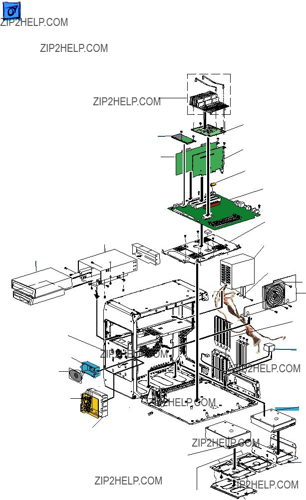
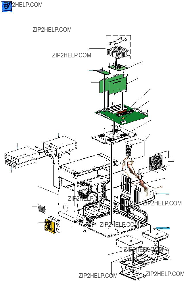
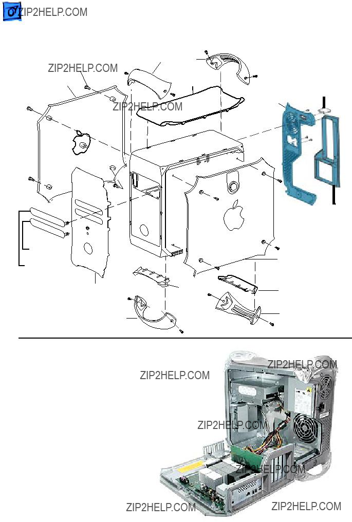
Power Mac G4 (AGP Graphics)
Support Plate

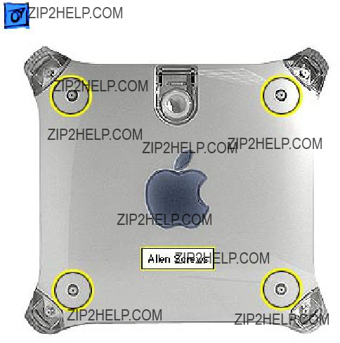
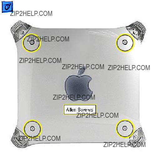
COVERS
Allen Screws Side Panels (typical)
Panel
Front and Rear
Top Handle


Top Panel
Allen Screws Handles
and Supports (typical)
Allen Security Screws (3) Bar Cover
Vented 

Panel
Note:
Logic Board, CD drive, Zip drive, power supply and hard drives are not part of the enclosure.

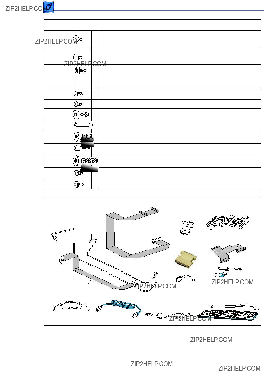
Cables
Front Panel Cable (Flat Gray)
IDE / ATA Cable
Adapter
 Mac to VGA
Cable Modem, Phone Ice
SCSI Adapter
Apple USB Keyboard
Power Mac G4 (Gigabit Ethernet)

COVERS
Allen Screws Side Panels (typical)
Panel
Front and Rear
Top Handle


Top Panel
Allen Screws Handles
and Supports (typical)
Allen Security Screws (3) Bar Cover
Vented 

Panel
Note:
Logic Board, CD drive, Zip drive, power supply and hard drives are not part of the enclosure.
USB Pro Mouse (optical)  922-4230

Power Mac G4 (Digital Audio)

COVERS
Allen Screws Side Panels (typical)
Panel
Front and Rear
Top Handle


Top Panel
Allen Screws Handles
and Supports (typical)
Allen Security Screws (3) Bar Cover
Vented 

Panel
Note:
Logic Board, CD drive, Zip drive, power supply and hard drives are not part of the enclosure.

(1) Modem, (1) Modem plug, (2) Carrier support plate, (1) Power supply bracket,
(4) Latch panel, (12) Logic board, (2) Firewire board, (2) Fan guard, (3) Chassis,
(1) Hard drive carrier retainer, (4) PCI slot covers (same screw can be used when cards installed)
USB Pro Mouse (optical)  922-4230
Power Mac G4 (QuickSilver)

COVERS
Allen Screws Side Panels (typical)
Panel
ZIP Bezel
Blank Bezel
Front Panel
Front Support
Front and Rear
Enclosure with Chassis
Note:
Logic Board, CD drive, Zip drive, power supply and hard drives are not part of the enclosure.

Power Mac G4 (QuickSilver)??? Screw Matrix
USB Pro Mouse (optical)  922-4230

Power Mac G4 (QuickSilver 2002)
CPU Heatsink Kit
Modem Card
Ultra 160 SCSI
Dual Chan PCI Card
Video Card
Logic Board
Battery
COVERS
Allen Screws Side Panels (typical)
Panel
ZIP Bezel
Blank Bezel
Front Panel
Front Support
Front and Rear
Enclosure with Chassis
Note:
Logic Board, CD drive, Zip drive, power supply and hard drives are not part of the enclosure.

Power Mac G4 (QuickSilver 2002)??? Screw Matrix
USB Pro Mouse (optical)  922-4230
Power Mac G4 (PCI Graphics)
Zip Drive (optional)
Fan Bracket
*Covers and Enclosure: See page 2. Cables and Screw Matrix: See page 3.
PCI Slots Shield
I / O Panel Kit
Hard Drive IDE 10GB
Ver. 2

COVERS
Allen Screws Side Panels (typical)
Panel
or

Enclosure with Chassis
Note:
Logic Board, CD drive, Zip drive, power supply, and hard drives are not part of the enclosure.