K Service Source
PowerBook 150
K Service Source
PowerBook 150

K Service Source
Basics
PowerBook 150

General Information
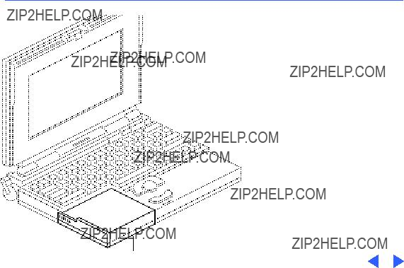
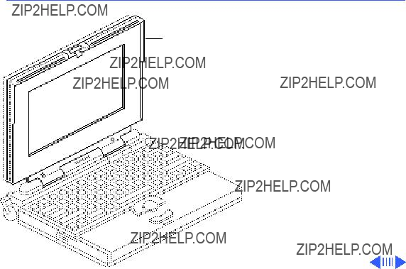
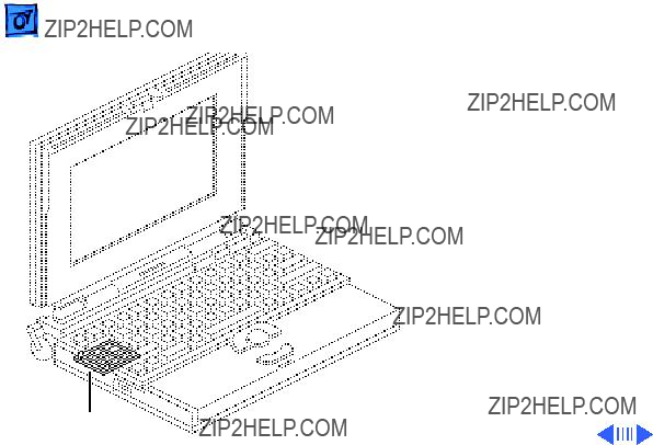
Figure: PowerBook 150
The PowerBook 150, shown at left, is an
The PowerBook 150 internal hard drive is based on IDE (Intelligent Device Electronics) technology, commonly used in

Rear Panel

K Service Source
Speci???cations
PowerBook 150

Introduction
You can also find specifications information for this product in the
Spec Database, which you can access in one of three ways:
???Launch it directly by
???Select "Apple Spec Database" from the Service Source drop- down main menu.
???Click the Acrobat toolbar icon for the database, which is near the right end of the toolbar with the letters "SP."


Sound and Video
Video Display
Sound Generator
9.5 in. diagonal screen
640 lines by 480 pixels
Apple sound chip provides

Electrical
Main Battery
Power Adapter
Nickel cadmium (NiCad) battery
Provides
US, Japanese, United Kingdom, Australian, and European versions


Shipping Altitude

K Service Source
Troubleshooting
PowerBook 150

General
The Symptom Charts included in this chapter will help you diagnose specific symptoms related to your product. Because cures are listed on the charts in the order of most likely solution, try the first cure first. Verify whether or not the product continues to exhibit the symptom. If the symptom persists, try the next cure. (Note: If you have replaced a module, reinstall the original module before you proceed to the next cure.)
If you are not sure what the problem is, or if the Symptom Charts do not resolve the problem, refer to the Flowchart for the product family.
For additional assistance, contact Apple Technical Support.

Power Manager Reset
Reset the power manager if
???The battery and power adapter are proven good, but the computer will not power on.
???The computer will not reset after a system crash.
To reset the power manager in a PowerBook 150,
???Remove the AC adapter and the battery.
???Using a paper clip, hold down the reset button on the back of the computer for
???Reconnect the AC adapter and briefly push the reset button again. You should hear a small pop from the speaker.
???Turn on the computer.
???If the computer powers on, reinstall the battery. If the computer does not start, it may need servicing.


 TroubleshootingSymptom Charts/Power - 5
Power


Computer runs when plugged in to wall outlet but not on battery power; battery voltage is within tolerance
1Reseat battery to make sure battery is mating with contacts on logic board.
2Replace fuse on logic board.
3Replace logic board.
4Return computer to Apple.

 TroubleshootingSymptom Charts/Video - 8
Video


Image is not uniform
Display stopped working or dimmed but is fine now
Backlight doesn???t operate
Irregularity in images is normal for FSTN screens. Adjust contrast and brightness to diminish effect.
If temperature is under 5 or over 40 degrees centigrade, this reaction is normal for FSTN screens.
1Check cables.
2Check display cable, inverter board, interconnect board, and logic board connections.
3Replace inverter board.
4Replace inverter cable.
5Replace interconnect board.
6Replace display.
7Replace logic board.


 TroubleshootingSymptom Charts/Floppy Drive - 13
Floppy Drive

 TroubleshootingSymptom Charts/Floppy Drive (Continued) - 14
Floppy Drive (Continued)
 TroubleshootingSymptom Charts/Floppy Drive (Continued) - 15
Floppy Drive (Continued)

 TroubleshootingSymptom Charts/Hard Drive - 16
Hard Drive

 TroubleshootingSymptom Charts/Peripherals - 17
Peripherals

 TroubleshootingSymptom Charts/Peripherals (Continued) - 18
Peripherals (Continued)

 TroubleshootingSymptom Charts/Peripherals (Continued) - 19
Peripherals (Continued)

 TroubleshootingSymptom Charts/Peripherals (Continued) - 20
Peripherals (Continued)

 TroubleshootingSymptom Charts/Peripherals (Continued) - 21
Peripherals (Continued)

 TroubleshootingSymptom Charts/Internal Modem - 22
Internal Modem

 TroubleshootingSymptom Charts/Internal Modem (Continued) - 23
Internal Modem (Continued)

 TroubleshootingSymptom Charts/Internal Modem (Continued) - 24
Internal Modem (Continued)
Miscellaneous
Screen goes blank and computer shuts down every few minutes
Adjust sleep delays in Control Panel or connect power adapter.

 TroubleshootingSymptom Charts/Miscellaneous (Continued) - 26
Miscellaneous (Continued)

K Service Source
Take Apart
PowerBook 150
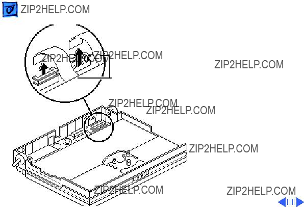
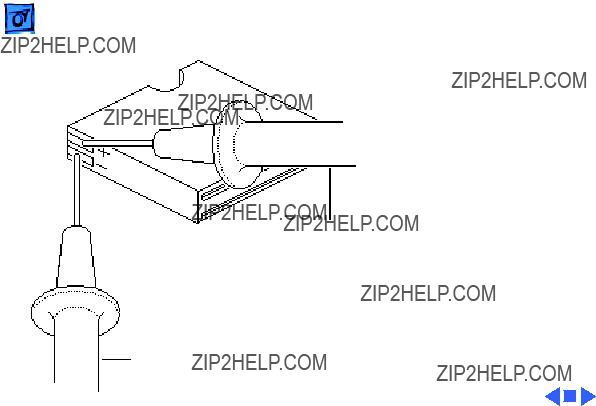
 Take ApartMain Battery - 1

2 Using the battery door as a handle, pull out the main battery.


Top Case
Before you begin, remove the main battery.
Caution: The PowerBook 150 contains CMOS devices
Top Casethat are very susceptible to ESD damage. Review the ESD precautions in Bulletins/ Safety.

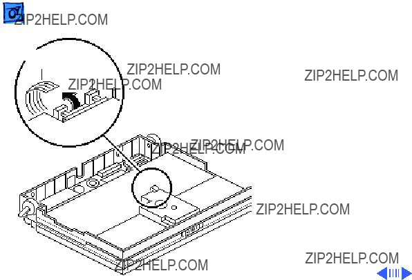
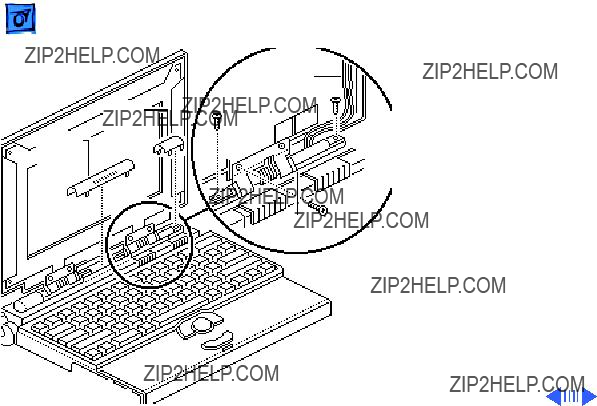
Interconnect
Cable
2Lift up the top case and disconnect the interconnect cable.
3Lift off the top case and unhook the two tab fasteners from the front of the bottom case.
Replacement Caution: When connecting the interconnect cable, fold the cable as shown. If it is not folded correctly, the cable could short.
Tab Fastener

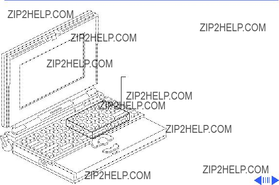
Hard Drive
Before you begin, remove the following:
??? Main battery
??? Top case
Caution: The PowerBook 150 contains CMOS devices that are very susceptible to ESD damage. Review the ESD precautions in Bulletins/ Safety.
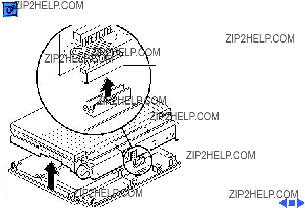
Hard Drive
Take ApartHard Drive - 8
Caution: The hard drive cable is fragile. Handle it with care.
1 Disconnect the hard drive cable from the logic board.

Hard Drive
Cable


Replacement Note: For information on returning drives, cables, and carriers to Apple, refer to the Hard Drives manual.
 Take ApartFloppy Drive - 12

Floppy Drive
Hard Drive
Cable
Caution: The hard drive cable is fragile and should be handled with care.
1Disconnect the hard drive cable from the logic board.
2Carefully fold back the cable from the floppy drive.
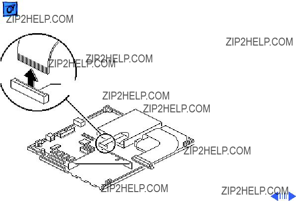
Locking
Tab
Caution: The floppy drive cable is fragile and should be handled with care.
3Lift the locking tab on the floppy drive connector and disconnect the floppy drive cable from the logic board.


Trackball
Assembly
Trackball
Assembly
Before you begin, remove the following:
??? Main battery
??? Top case
Caution: The PowerBook 150 contains CMOS devices that are very susceptible to ESD damage. Review the ESD precautions in Bulletins/ Safety.
Trackball Locking
Cable Tab
Caution: The trackball cable is fragile and should be handled with care.
1Pull out the locking tab on the trackball connector and disconnect the trackball cable.

 Take ApartKeyboard - 21
Keyboard
Cables
Caution: The keyboard ribbon cables are fragile and should be handled with care.
1Lift up the locking tabs on the two keyboard connectors and disconnect the keyboard cables.


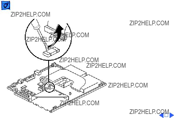
 Take ApartInverter Board - 24

Inverter
Shield
Inverter
Board
Inverter
Cable
1Remove the two mounting screws that secure the inverter board to the bottom case.
2Note: Do not remove the inverter shield from the inverter board.
Pull the inverter board and attached shield straight up and off the connector on the interconnect board.
3Disconnect the inverter cable.
Replacement Note: Inverter
shields are available from

 Take ApartInterconnect Board - 27
Interconnect Board
Before you begin, remove the following:
??? Main battery
??? Top case
??? Inverter board
Caution: The PowerBook 150 contains CMOS devices that are very susceptible to ESD damage. Review the ESD precautions in Bulletins/ Safety.
Interconnect Board
Take ApartInterconnect Board - 28
??Warning: The interconnect board contains hazardous materials. Return bad interconnect boards to Apple for proper disposal.
1 Caution: The keyboard and display ribbon cables are fragile. Handle these cables with care.
Lift up the locking tabs on the two keyboard connectors and disconnect the keyboard cables.


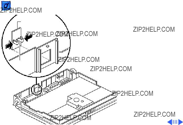
 Take ApartActuators - 31

Elevation Feet
Before you begin, remove the following:
??? Main battery
??? Top case
Caution: The PowerBook Elevation Foot 150 contains CMOS devices
that are very susceptible to ESD damage. Review the ESD precautions in Bulletins/ Safety.
Elevation Foot

Spring
Clip
Elevation
Foot
1Using a
2Pull off the elevation foot.
Fuse
Before you begin, remove the following:
??? Main battery
??? Top case
Caution: The PowerBook 150 contains CMOS devices that are very susceptible to ESD damage. Review the ESD precautions in Bulletins/ Safety.
Fuse

 Take ApartLogic Board - 37
Logic Board
Before you begin, remove the following:
??? Main battery
??? Top case
??? RAM expansion card (if present)
??? Modem board (if present)
Caution: The PowerBook 150 contains CMOS devices that are very susceptible to ESD damage. Review the ESD precautions in Bulletins/ Safety.
Logic Board
 Take ApartDisplay Bezel - 40
Display Bezel

Screw
Plastic Plugs
Plastic
Plug
1Remove the two plastic plugs.
2Using a

 Take ApartClutches/Display Housing - 43


Inverter
Cable
Clutch Covers
Right
Clutch
5Pull off the three clutch covers.
6Using a
7Remove the left and right clutches from the display housing.
Replacement Note: Replace the short mounting screws in the


 Take ApartDisplay - 47

Locking
Tab
5Using a small

Backlight
Cable

 Take Apart
Display Cable
Display Cable - 51
Display Cable
Before you begin, remove the following:
??? Main battery
??? Top case
??? Inverter board
??? Interconnect board
??? Display bezel
??? Display
Caution: The PowerBook 150 contains CMOS devices that are very susceptible to ESD damage. Review the ESD precautions in Bulletins/ Safety.

Ferrite Bead

Center
Left Clutch
Clutch Cover
Cover
Display
Cable
Replacement Note: Replace the short mounting screw in the
5Remove the display cable from the case.

Display Housing
Inverter Cable
Right
Clutch
Center Cover
Clutch
Cover
Inverter
Cable
Right
Clutch
1Pull off the center and right clutch covers.
2Using a
3Remove the clutch from the display housing.
Replacement Note: Replace the short mounting screw in the


K Service Source
Upgrades
PowerBook 150
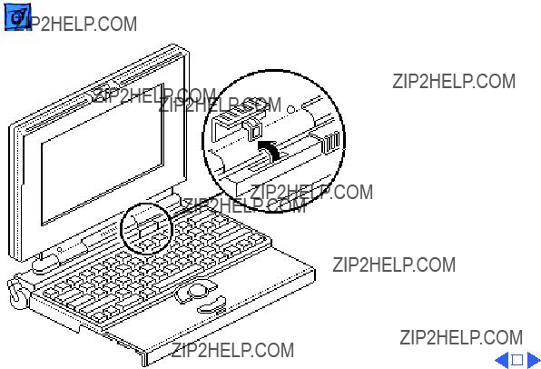
 UpgradesModem Card - 1
Modem Port Cover
Release
Tabs
Note: The modem card is an option for the PowerBook 150.
1Pinch the release tabs and push out the modem port cover.

Modem
Modem Card Connector
J4 Connector
2Connect the modem card connector to connector J4 on the logic board.
3Install the two mounting screws.
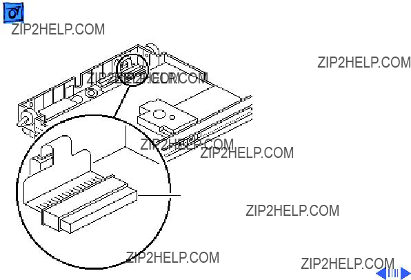
RAM Expansion
Card
Before you begin, remove the following:
??? Main battery
??? Top case
Caution: The PowerBook 150 contains CMOS devices that are very susceptible to ESD damage. Review the ESD precautions in Bulletins/ Safety.
RAM Expansion Card


 Upgrades
J7 Connector
Brace Slot
RAM Expansion Card - 7
3Insert the two legs of the expansion card brace into the two brace slots in the logic board.
4Caution: Be careful not to flex the RAM card or adapter when connecting the adapter to the logic board.
Connect the adapter (with RAM card and brace attached) to connector J7 on the logic board.
5Install the mounting screw.

 Upgrades
Adapter
Logic Board
Tool
RAM Expansion Card - 8
Note: To disconnect the adapter from the logic board, be sure to use the Apple logic board
Note: To verify that the upgrade is successful, check the Total Memory message (for systems with virtual memory switched off) or the


K Service Source
Additional Procedures
PowerBook 150
Battery
LED
Battery
Recharger
Battery Recharger
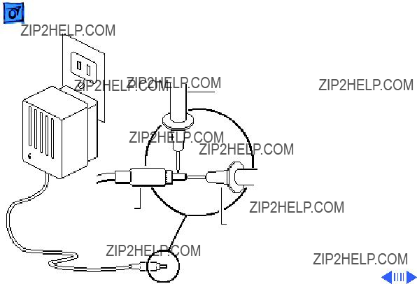
No preliminary steps are required before you begin this procedure.
1Using the PowerBook power adapter, plug the battery recharger into a power outlet and insert the main battery into the recharger.

 Additional ProceduresBattery Handling - 3


 Additional ProceduresBattery Verification - 6
Negative Probe
Adapter
Plug
Negative
Probe
Positive
Probe
Adapter
Verification
No preliminary steps are required before you begin this procedure.
1Plug in the AC adapter to a wall socket.
2Set a voltmeter to the 10 volts DC scale.
3Touch the positive voltmeter probe to the inside of the adapter plug, and touch the negative voltmeter probe to the outside of


K Service Source
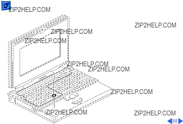
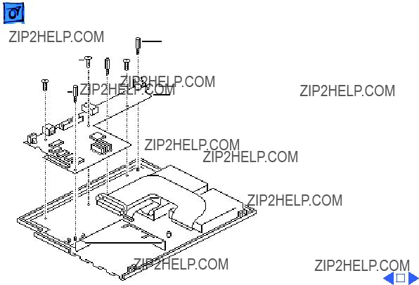
Exploded View
PowerBook 150
Exploded View
PowerBook 150
 EMI Shield
DRAM Expansion Card
Motherboard Insulator
 Battery
Door
This is a generic representation of a product family. Configurations may vary.