K Service Source
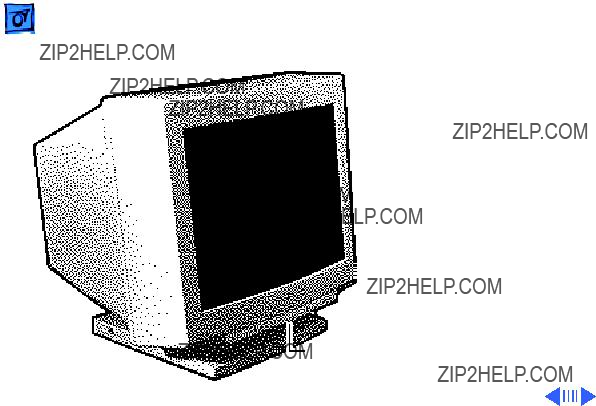
Apple Multiple Scan 20
Display
Apple Multiple Scan 20 Display Apple Multiple Scan 20 Display, Rev. B
K Service Source
Apple Multiple Scan 20
Display
Apple Multiple Scan 20 Display Apple Multiple Scan 20 Display, Rev. B

K Service Source
Basics
Apple Multiple Scan 20 Display

Version Differences
Overview
The Apple Multiple Scan 20 Display and Apple Multiple Scan 20 Display Rev. B have the same overall appearance. However, the Rev. B version offers improved performance and better screen resolution.
To distinguish the two versions, check the last three digits of the serial number. The serial number for the Rev. B version ends in one of the following:
??? 5B4
??? 5J2
??? 5JE
??? 5JF

Multiple Scan 20 Display
Dot pitch 0.31 mm.
Multiple Scan 20 Display, Rev. B
Dot pitch 0.26 mm.
Requires Rev. B parts for Main Deflection Board, Microprocessor Controller Board, and Power Supply.
As you go through this manual, consider the information applicable to both versions unless specified otherwise.

Monitor Distortion
Overview
All
Important: Even monitors set to factory specifications may appear distorted when set up in a new environment.
Common environmentally caused distortions are shown on this and the following cards. Always check first for environmental causes before attempting to exchange or adjust a monitor with a distorted raster.
Ideal Raster

Environmental In???uences
The following environmental conditions may distort the raster:
??? Proximity to metal objects, such as metal desks, file cabinets, and bookshelves. Metal objects affect the earth???s magnetic field. Earth magnetism usually distorts only the edges of the screen.
??? Fluorescent lights, other monitors, or electronic appliances such as coffee makers and copy machines. These objects cause dynamic raster distortion, that is, movement or jitter of the image.
Right Edge Not Straight

Troubleshooting
Important: Exchanging the monitor cannot correct environmental distortion problems.
Note: If the monitor has shifted up/down or right/left only, go ahead and adjust it using the user controls. However, keep in mind that if you then move the monitor you may need to readjust the centering controls.
Before adjusting a monitor with a distorted raster, try the following:
??? Swivel or move the monitor, or
??? Remove the monitor from the building and recheck it in another location.

If the display changes (for better or worse) when you move it to another location, the environment is the source of the problem. Relocate your monitor or remove the distortion- causing object.
If the display does not change when you move it to another location, continue troubleshooting the problem (refer to Troubleshooting).

EEPROM Settings
Caution: To prevent data loss or corruption, always save EEPROM settings before you replace the microprocessor board.
See Troubleshooting for instructions on saving the EEPROM settings from the old microprocessor board and restoring the settings on the new microprocessor board.
If the settings are lost before they can be written to the new EEPROM, the display will be impossible to repair, and the whole display will need to be replaced.

Microprocessor Board
K Service Source
Speci???cations
Apple Multiple Scan 20 Display

Characteristics
Picture Tube
Bonded glass panel with antiglare/antistatic multilayer coating
Screen Resolution
640x480 to 1280x1024
Scan Rates
Cable Connector
Vertical refresh range: 50 to 150 Hz
Horizontal scan range: 29 to 82 kHz Macintosh, VGA, SVGA, and VESA compatible

System
Requirements
Power Macintosh, Macintosh Centris, Macintosh Quadra, or any NuBus compatible Macintosh with a Macintosh Display Card 24AC.
Macintosh II family, PowerBooks, Duo and Mini Dock, Macintosh Performa, Macintosh LC, LC II, LC III, and Macintosh computers with Display Cards 4???8, 8???24, 8???24GC work in 640x480 mode. Other modes possible with additional adapters.
System software version 7.1 or later

User Controls
I/O Ports
Controls and Ports
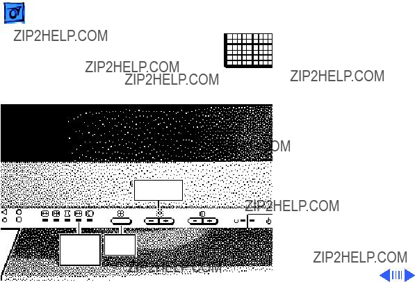
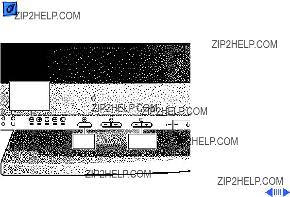
Front panel: power, reset, and control buttons; brightness and contrast controls
Additional controls available using the command button: horizontal and vertical shift, horizontal and vertical size, rotation, horizontal and vertical convergence, and color temperature
Automatic degauss at power on; manual degauss by turning power switch off, then on (capable of full degauss after monitor is turned off for 20 minutes or more)
Two Apple Desktop Bus (ADB) ports and one ADB

Physical and Electrical
Power Supply
Universal power supply
Voltage:
Frequency:
Power: 165 W maximum (less than 15 W in
Size and Weight
Height: 18.5 in. (474 mm)
Width: 18.5 in. (474 mm)
Depth: 19.6 in. (501.5 mm)
Monitor weight: 66 lb. (30 kg)
Fully boxed weight: 80 lb. (36 kg)


Altitude
Humidity
Power Savings
Feature
Operating: to 10,000 ft. (1,067 m)
Shipping: to 35,000 ft. (3,048 m)
Operating:
Storage:
Shipping:
Conforms to the Energy Star Program of the United States Environmental Protection Agency
K Service Source
Troubleshooting
Apple Multiple Scan 20 Display

General
The Symptom Charts included in this chapter will help you diagnose specific symptoms related to your product. Because cures are listed on the charts in the order of most likely solution, try the first cure first. Verify whether or not the product continues to exhibit the symptom. If the symptom persists, try the next cure. (Note: If you have replaced a module, reinstall the original module before you proceed to the next cure.)
If you are not sure what the problem is, or if the Symptom Charts do not resolve the problem, refer to the Flowchart for the product family.
For additional assistance, contact Apple Technical Support.

First Checklist
Important: Over 60% of the Apple Multiple Scan 20 Display modules returned for repair are found to be fully operational. Read this checklist before you return a module. Prevent needless module replacement and unnecessary time delays.
 The Apple Multiple Scan 20 Display is not fully compatible with all Macintosh computers and PowerBooks.
If you suspect a loss of functionality, especially with the number of screen resolutions available (in Control Panels), check the Tech Info Library or contact Apple Technical Support.

The CRT raster will not always resemble a perfect rectangle.
CRT tolerances allow for some distortion. Additional distortion can be caused by magnetized metal objects (desks, file cabinets, etc.). Move the unit to a different location if you notice raster bowing or bent raster edges.
 Jitter, faint lines, or screen movement can be caused by external interference such as electronic devices and fluorescent lights.
Move the unit to another room or building to help determine if external interference is the source of the problem.

A misadjusted screen can mimic the symptoms of deflection board or CRT failures.
By performing the adjustment procedures, you might determine if one or more of the adjustments is the cause of the problem.

 CRTs rarely fail.
Needless CRT replacements can be prevented by checking display adjustments, checking the possibility of other defective modules, and accepting small imperfections in screen display.
If you have any doubts about whether a CRT is defective, contact Apple Technical Support.

Display Setting Restoration
Each Multiple Scan 20 Display has an EEPROM (located on the microprocessor controller board) that contains adjustment information specific to that monitor. Before you replace the microprocessor board, save this EEPROM information.
Use MacTest Pro Display Setting Restore Utility to preserve the monitor adjustment settings.
Connect the Hardware
There are two ways to connect the hardware to use the MacTest Pro Display Setting Restore Utility:
1 Connect a serial cable (MINI


Save the EEPROM Information
To save information from the old EEPROM, create a data file:
1 Start MacTest Pro.
2 Choose ???Apple Multiple Scan 20 Display.???
3 Select ???Test.???
4 Click ???Create File.???
Install the Microprocessor Board
See Take Apart for instructions on installing the new microprocessor board.

Troubleshooting Display Setting Restoration/Restore the EEPROM Information -
After the new microprocessor board is installed, the new EEPROM will have default settings that allow you to read the display, but with difficulty. When the settings from the old EEPROM are transferred to the new EEPROM, the display should be clear and the last color temperature mode chosen restored.
Restore the EEPROM Information
To download the saved adjustment information to the new EEPROM,
1 Start MacTest Pro.
2 Choose ???Apple Multiple Scan 20 Display.???
3 Select ???Test.???
4 Click ???Write File.???

Caution: To prevent data loss or corruption, always save EEPROM settings before you replace the microprocessor board.

Raster edges have color blotches when displaying an all- white screen
1Degauss monitor with an external degaussing coil.
2Move monitor to different location and repeat degaussing procedure.
Note: This symptom is caused by strong magnetic fields in the environment. Exchanging boards will not cure the symptom. Refer to ???First Checklist??? in this chapter.


 TroubleshootingSymptom Charts/Power - 13
Power

Indicator Lights
Convergence indicator light blinks or stays on; power indicator light might also blink
Replace microprocessor board after downloading settings as described in ???Display Setting Restoration??? in this chapter.
Caution: To prevent data loss or corruption, always save EEPROM settings before you replace the microprocessor board.

 TroubleshootingSymptom Charts/Indicator Lights (Continued) - 15

Indicator Lights (Continued)
Size indicator light blinks or stays on; power indicator light might also blink
1Replace main deflection board.
2Replace CRT/video board.
3Replace microprocessor board after downloading settings as described in ???Display Setting Restoration??? in this chapter.
Caution: To prevent data loss or corruption, always save EEPROM settings before you replace the microprocessor board.

Indicator Lights (Continued)
Centering indicator light blinks or stays on; power indicator light might also blink
1Replace main deflection board.
2Replace microprocessor board after downloading settings as described in ???Display Setting Restoration??? in this chapter.
Caution: To prevent data loss or corruption, always save EEPROM settings before you replace the microprocessor board.

 TroubleshootingSymptom Charts/Miscellaneous - 18
Miscellaneous

 TroubleshootingSymptom Charts/Miscellaneous (Continued) - 19
Miscellaneous (Continued)
Miscellaneous (Continued)
Upon first use, monitor screen shows
1Select the all white display pattern, and adjust size and rotation controls on the monitor???s front panel. Aim for reducing the visibility of the lines while minimizing discoloration.
2At
3Call Service Provider Support at

K Service Source
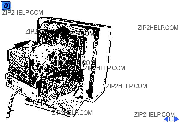
Take Apart
Apple Multiple Scan 20 Display

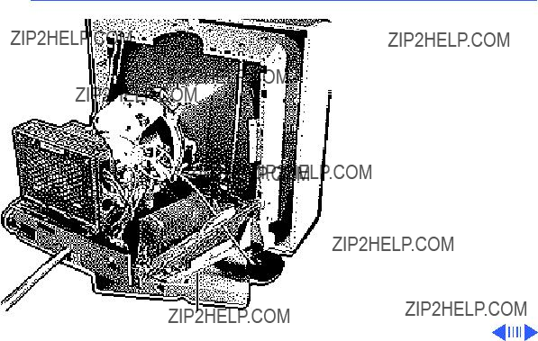
Rear Cover
No preliminary steps are required before you begin this procedure.
??Warning: This product contains high voltage and a
Rear Cover To prevent serious injury, review CRT safety in Bulletins/Safety.

 Take Apart
Video
Cable
Rear Cover - 2
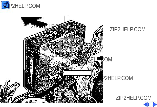
1With the monitor face- down on a protective pad, remove the four case screws and pull the rear cover off the chassis.
2Route the video cable through the cover.

 Take Apart
Bezel
Bezel - 3
Bezel
Before you begin, remove the following:
??? Rear cover
??? EMI shield
??Warning: This product contains high voltage and a

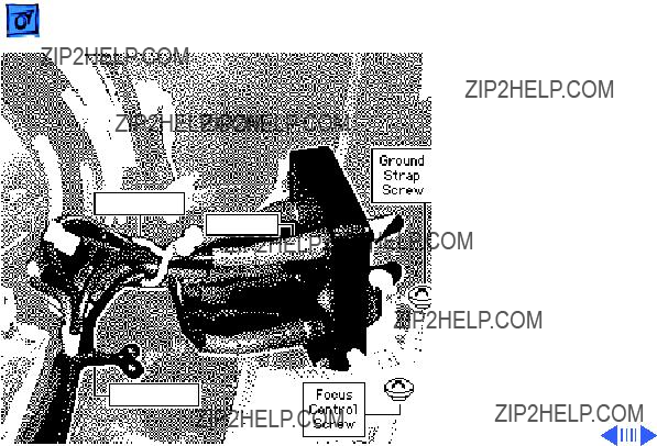
Grounding Screw


 Take Apart
EMI Shield
EMI Shield - 6
EMI Shield
Before you begin,
??? Remove the rear cover
??? Discharge the CRT
??Warning: This product contains high voltage and a
??Warning: Never use a grounding wriststrap until after discharging the CRT.
Note: The EMI shield is not replaceable.

 Take Apart
EMI Shield
EMI Shield - 7
1Remove the 12 screws from the shield. (Three screws are located on the left side of the EMI shield.)

 Take Apart
EMI Shield
EMI Shield - 8
2Slide the shield toward the back of the monitor and lift off the shield.
 Take Apart
CRT/Video
Board
CRT/Video Board - 9
CRT/Video Board
Before you begin,
??? Remove the rear cover
??? Discharge the CRT
??? Remove the EMI shield
??Warning: This product contains high voltage and a
NTC Connector
Ground Strap
??Warning: Never use a grounding wriststrap until after discharging the CRT.
1Caution: When removing the ground strap from the CRT/ video board, be careful not to apply excessive pressure to the neck of the CRT.
Disconnect the ground strap from the terminal on the front of the CRT/ video board shield.
2Disconnect the NTC connector.

 Take Apart
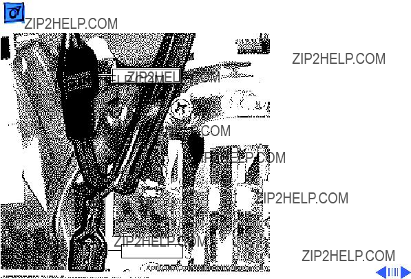
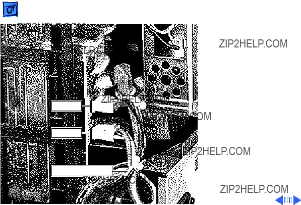
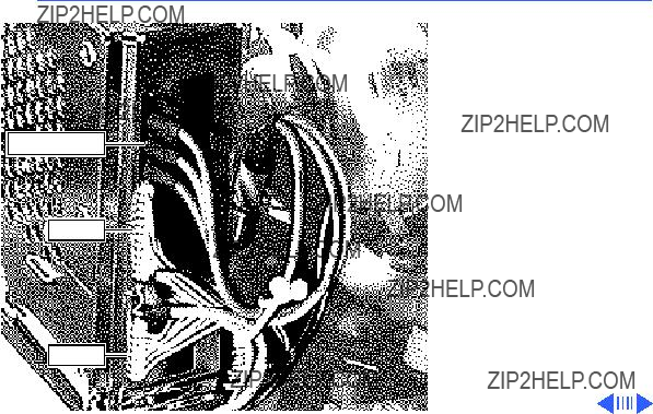
R,G,B Cables
CN302
CN301
CN303
CRT/Video Board - 11
Caution: When disconnecting the following cables from the CRT/video board, be careful not to apply excessive pressure to the neck of the CRT.
3Disconnect these cables from the CRT/video board:
???
???
???
???R, G, and B video cables
CN304
CN701
CN702
Caution: When disconnecting the following cables from the CRT/video board, be careful not to apply excessive pressure to the neck of the CRT.
4Disconnect these cables from the CRT/video board:
???
???
???

Take ApartCRT/Video Board - 13
Caution: When removing the video cable from the CRT/video board, be careful not to apply excessive pressure to the neck of the CRT.
Mounting Screw

FV1 Cable
FV2 Cable
7Remove the two plastic cable clips on the focus VR control cables.
8Disconnect the FV1 and FV2 cables from the focus control board.
Plastic Cable Clip

Power Supply
Before you begin,
??? Remove the rear cover
??? Discharge the CRT
??? Remove the EMI shield
??Warning: This product contains high voltage and a
??Warning: Never use a grounding wriststrap until after discharging the CRT.
Power Supply
GroundCN602
Strap
CN603
CN604
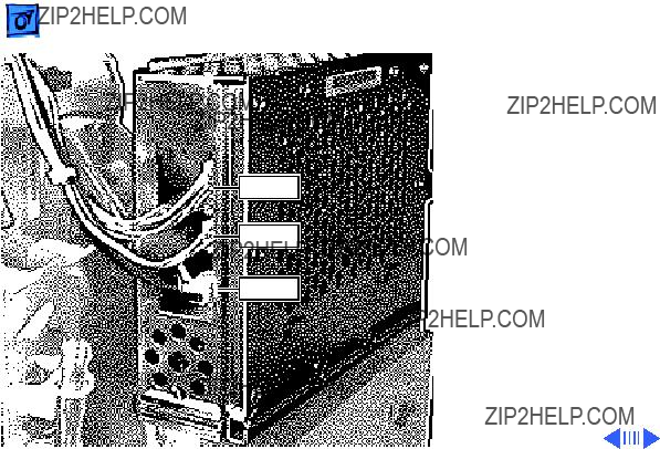
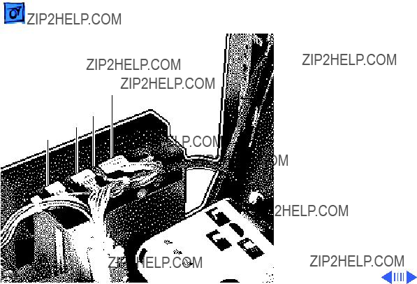
1Disconnect these cables from the power supply:
???
???5 - wire cable (CN603)
???
???Ground strap
2Remove the wiring harness from the plastic cable clip.
CN1601
CN1600
Plastic Cable Clips

CN601

 Take ApartFuse - 21
Fuse
Before you begin,
??? Remove the rear cover
??? Discharge the CRT
??? Remove the EMI shield
??? Remove the power supply
??Warning: This product contains high voltage and a
Fuse

 Take Apart
Fuse Holder
Fuse - 22
??Warning: Never use a grounding wriststrap until after discharging the CRT.
1Remove the plastic cover from the fuse holder.
2Pry the fuse from the fuse holder using a jeweler???s screwdriver.
Replacement Note: Be sure to replace the fuse with another fuse of the same amperage and voltage rating.

Focus VR Control
Before you begin,
??? Remove the rear cover
??? Discharge the CRT
??? Remove the EMI shield
??Warning: This product contains high voltage and a
Focus VR Control

FV1 Cable
VIDF Cable
HIDF Cable
??Warning: Never use a grounding wriststrap until after discharging the CRT.
1Disconnect these cables from the focus control:
???MV
???FV1
???FV2
???VIDF
???HIDF

 Take Apart
Focus Control
Focus VR Control - 25
2Remove the screw securing the ground strap to the chassis.
3Remove the screw securing the focus control to the chassis.
4Lift out the focus control.
Ground
Strap
Focus Control Screw
Screw

 Take ApartAC Inlet Assembly - 26
AC Inlet Assembly
Before you begin,
??? Remove the rear cover
??? Discharge the CRT
??? Remove the EMI shield
??? Remove the power supply
??Warning: This product contains high voltage and a
AC Inlet Assembly

 Take Apart
CN1601
CN1600
AC Inlet Assembly - 27
??Warning: Never use a grounding wriststrap until after discharging the CRT.
1Disconnect these cables from the AC interconnect board:
???CN1600
???CN1601
2Remove the screw securing the AC inlet ground strap to the chassis.
Screw

 Take Apart
Screw
AC Inlet Assembly - 28
3Remove the two screws securing the AC inlet assembly to the chassis.
4Lift out the AC inlet assembly.
Screw
AC Inlet
Assembly
 Take ApartSerial I/O Board - 29

Video Cable
Before you begin,
??? Remove the rear cover
??? Discharge the CRT
??? Remove the EMI shield
??Warning: This product contains high voltage and a
??Warning: Never use a grounding wriststrap until after discharging the CRT.
Video Cable

R,G,B Cables
CN253
1Disconnect connector CN253 from the serial I/O board.
2Disconnect the R, G, and B cables from the CRT/ video board.
Serial I/O Board
4 Remove the plastic cable clip.

Rear Panel

 Take ApartMain Deflection Board - 37
Main Deflection
Board
Before you begin,
??? Remove the rear cover
??? Discharge the CRT
??? Remove the EMI shield
??? Remove the power supply
??Warning: This product contains high voltage and a
Main Deflection Board
Plastic Clip
MV Cable
Plastic Clip
1Disconnect the MV cable from the focus VR control.
2Remove the two plastic cable clips on the focus VR control cables.
3Remove the screw securing the ground strap to the chassis.
4Remove the screw securing the focus control to the chassis.
5Lift out the focus control and let it hang outside the chassis.
CN250
 Take Apart
R,G,B Cables
CN302
CN303
Main Deflection Board - 40
7Caution: When disconnecting the following cables from the CRT/video board, be careful not to apply excessive pressure to the neck of the CRT.
Disconnect these cables from the CRT/video board:
???
???
???R, G, and B video cables


Screw

 Take ApartMicroprocessor Board - 46


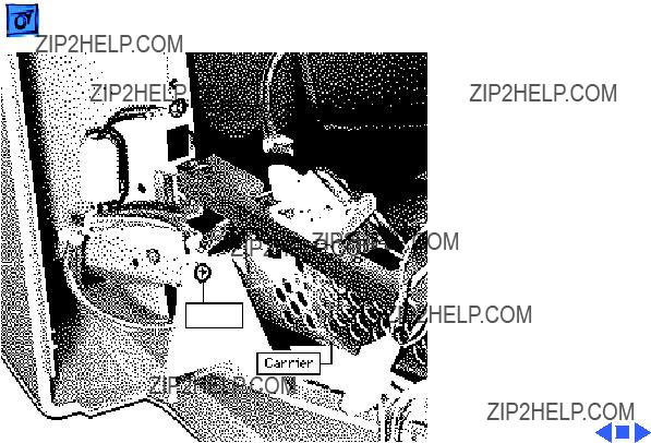
 Take ApartTilt/Swivel Assembly - 49
Tilt/Swivel
Assembly
Before you begin,
??? Remove the rear cover
??? Discharge the CRT
??? Remove the EMI shield
??? Remove the power supply
??? Remove the main deflection board
??Warning: This product contains high voltage and a
Tilt/Swivel
Assembly


 Take ApartControl Panel - 51
Control Panel
Before you begin,
??? Remove the cover
??? Discharge the CRT
??? Remove the anode cap
??? Remove the EMI shield
??? Remove the power supply
??? Remove the main deflection board
??? Remove the tilt/swivel assembly
Control Panel


ADB Board
No preliminary steps are required before you begin this procedure.
ADB Board


K Service Source
Adjustments
Apple Multiple Scan 20 Display

Brightness and
Contrast
No preliminary steps are required before you begin this procedure.
Adjustment controls are located on the front panel.
Front Panel

Brightness
1 Press the + button to increase the brightness.
2 Press the ??? button to decrease the brightness.
Brightness
Controls
Contrast
1 Press the + button to increase the contrast.
2 Press the ??? button to decrease the contrast.
Contrast
Controls

Geometry
No preliminary steps are required before you begin this procedure.
Adjustment controls are located on the front panel.
Front Panel

Vertical Center
1 Press the select button Crosshatch to turn on the centering
indicator light.
2 Press the + or ??? button on the brightness controls to move the center of the picture up or down.
Centering
Indicator Brightness
Light Controls
Select
Button

Horizontal Center
1 Press the select button Crosshatch to turn on the centering
indicator light.
2 Press the + or ??? button on the contrast controls to move the center of the picture right or left.
Centering
Indicator
Light
Vertical Size
1 Press the select button Crosshatch repeatedly until the size
indicator light goes on.
2 Press the + or ??? button on the brightness controls to increase or decrease the size of the picture.
Brightness
Controls
Size Select
Indicator Button
Light

Horizontal Size
1 Press the select button Crosshatch repeatedly until the size
indicator light goes on.
2 Press the + or ??? button on the contrast controls to increase or decrease the size of the picture.

Rotation and Color
Uniformity


 Adjustments
Rotation
Indicator
Light
Geometry - 11
Shape
1 Press the select button Crosshatch repeatedly until the
rotation indicator light goes on.
2Press the + button on the contrast controls to expand the sides of the picture.
3Press the ??? button on the contrast controls to bring in the sides of the picture.
Convergence
No preliminary steps are required before you begin this procedure.
Adjustment controls are located on the front panel.
Note: When the convergence is set properly, the picture is crisp and clear.
Front Panel
Vertical Convergence
1 Press the select button Crosshatch repeatedly until the
convergence indicator light goes on.
2Press the + button on the brightness controls to move the red signal up and the blue signal down.
3Press the ??? button on the brightness controls to move the red signal down and the blue signal up.
Select
Button

Convergence
Indicator
Light
Crosshatch
Horizontal
Convergence
1Press the select button repeatedly until the convergence indicator light goes on.
2Press the + button on the contrast controls to move the red signal to the right and the blue signal to the left.
3Press the ??? button on the contrast controls to move the red signal to the left and the blue signal to the right.

 AdjustmentsColor Temperature - 15

Color
Temperature
Indicator
Light
1Press the select button repeatedly until the color temperature indicator light goes on.
Note: The indicator may or may not blink, depending on the color temperature selected. A steady light indicates 9300 K, a slow blinking light indicates 6500 K, and a fast blinking light indicates 5000 K.

Color
Temperature
Indicator
Light
2Press the + button on the contrast controls to increase the color temperature.
3Press the ??? button on the contrast controls to decrease the color temperature.

Factory Settings
No preliminary steps are required before you begin this procedure.
Important: The monitor controls are set at the factory. To
Front Panel

Recall
Note: You can reset brightness and contrast to their factory levels; however, you cannot reset one or the other. You must reset both controls.
Use a straightened paper clip to push in the reset button.
Reset
Button

Picture
Control
Indicator
Lights
Reset a Speci???c
Control
1Press the select button repeatedly until the indicator light of the picture control you want to reset (vertical or horizontal center, convergence, or color temperature) goes on.
2Use a straightened paper clip to push in the reset button.
The selected picture control is reset to its original level.

 Adjustments
Control
Button
Reset
Button
Factory Settings - 22
Reset All Controls
While holding down the control button, push in the reset button with a straightened paper clip.
All picture controls are reset to their factory levels.
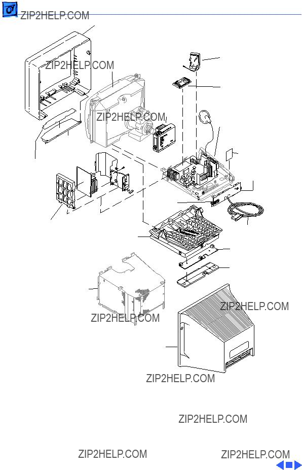
K Service Source
Exploded View
Apple Multiple Scan 20 Display