

Installation
Instructions
R520
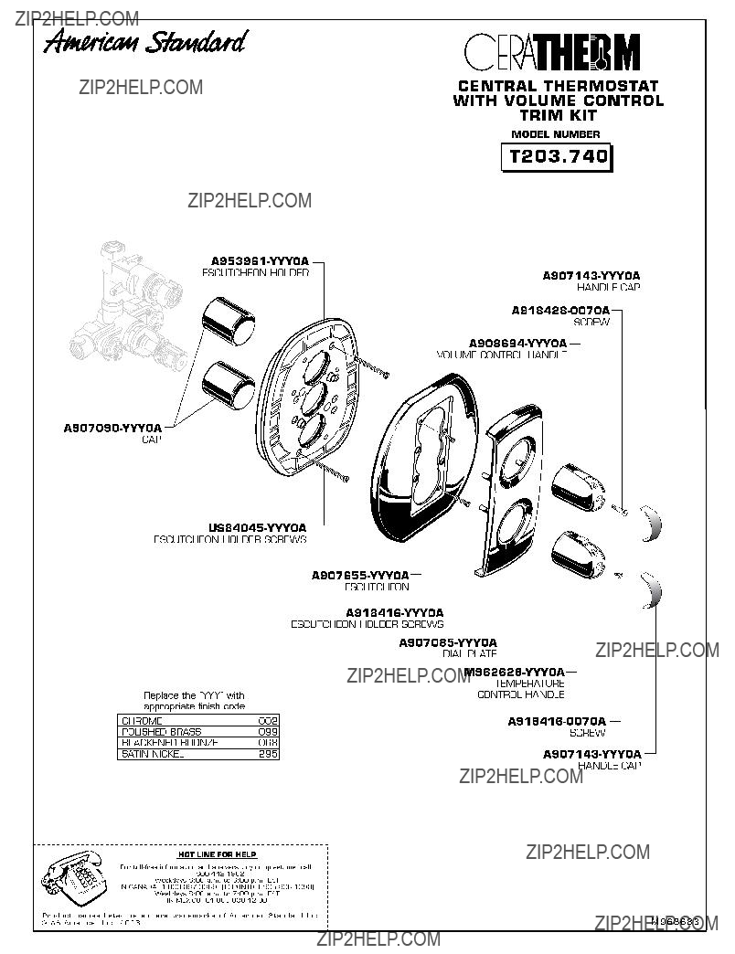
CENTRAL THERMOSTAT
WITH VOLUME CONTROL
Thank you for selecting
To ensure that your installation proceeds
Certi???ed to comply with ANSI A112.18.1M ASSE 1016
M968255Rev.1.1
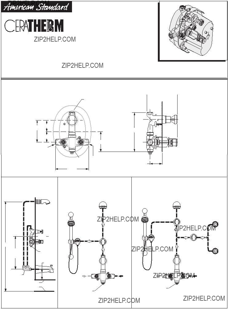
CONNECTIONS ARE: 1/2" NPT


1/2" NPT
SHOWER
Prepare water supplies per
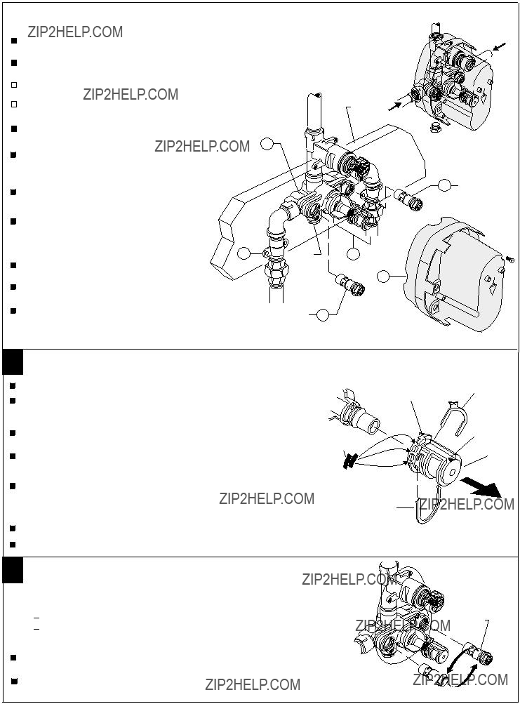
Install VALVE at indicated height and depth. Make sure the "TOP" marking on the PLASTER GUARD is up.
COLD
 PLUG TUB
PORT
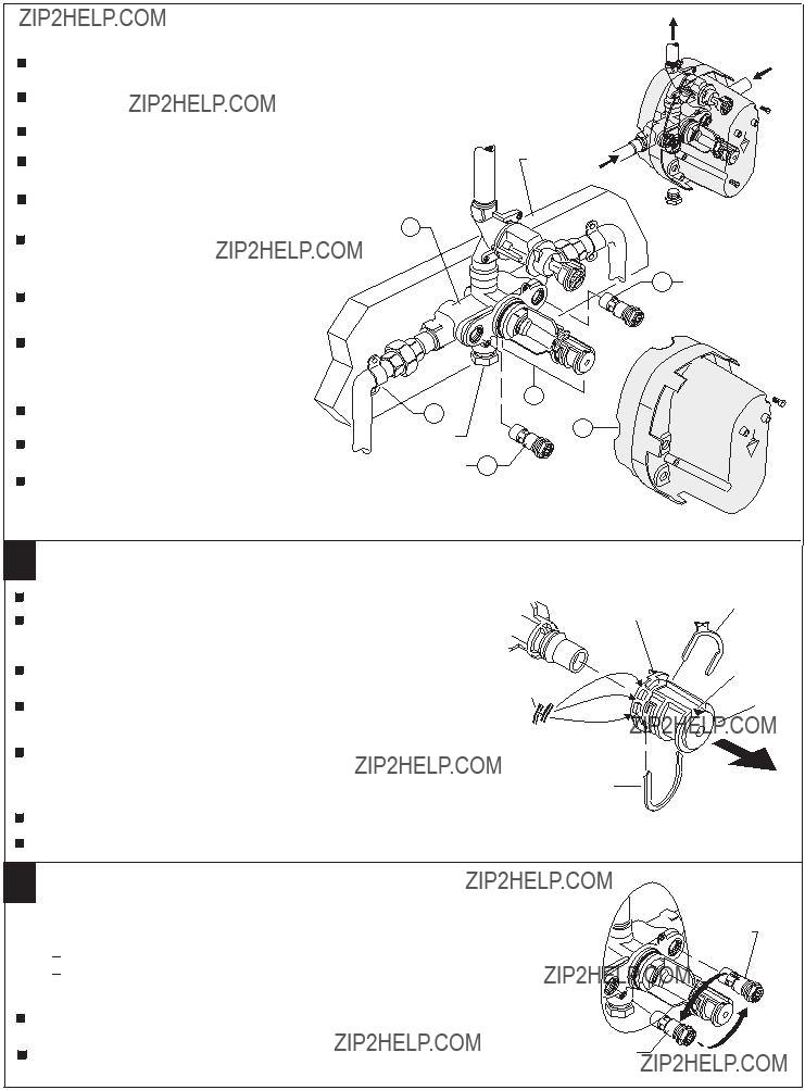
CHECK STOPS (4,5) are supplied in the open position. Closing using 5/32" (4 mm) hex wrench to pressure test and to check for leaks.
To ???ush lines, remove the CHECK STOPS (4,5) and run water. If desired, the TEMPERATURE CONTROL UNIT can be removed. Reinstall CHECK STOPS (4,5) and CONTROL UNIT (6), if it was removed.
Remove PLASTER GUARD (2) if still installed. Turn on water supplies and check for leaks.
Reassemble PLASTER GUARD (2) and FINISH
WALL.
Beware of Freezing. No water should remain in the MIXING VALVE if freezing is a possibility. Remove the CHECK STOPS (4,5) to completely drain the MIXER UNIT (1).
HOT
6
3
2
PLUG TUB
PORT
CHECK STOP 4 (HOT RED)
TOP
2 TEMPERATURE ADJUSTMENT
Unscrew PLASTER GUARD SCREWS and remove PLASTER GUARD.
ARROW "B"
Check that arrow marking B points vertically upwards. If not, push the BLACK
CLAMP on the SECURING RING to the right, pull off KNOB MOUNT and reinstall
KNOB MOUNT with arrow "B" pointing upwards.
BLACK
CLAMP
ARROW "A"
KNOB
Remove the TEMPERATURE LIMIT STOP (H shaped Black Plastic part). Reinstall it at the desired notch as indicated in the diagram to limit the maximum mixed water temperature to 104 F or 112 F.
For 100 F adjustment, turn the water supply on. Turn KNOB MOUNT until the spout temperature is 100 F. Check that arrow marking A on the KNOB MOUNT still points upward after adjusting the thermostat to 100 F. If not, pull out the RED LOCKING DEVICE. Remove KNOB MOUNT by pulling it towards you while standing directly in front of the valve.
Reinstall the KNOB MOUNT so that the arrow marking A points upwards.
Reinstall RED LOCKING DEVICE.
109
112
SECURING 
RING
RED LOCKING
DEVICE
MOUNT
3 TRANSPOSED SUPPLY PIPING
OR BACK TO BACK INSTALLATION
Should the hot and cold water supply pipes have been transposed making adjustment impossible, proceed as follows:

 Shut off water supply.

 Remove handle and rim
 Remove check stops and
Important note: RED CHECK STOP is now on the right of the mixer body and the BLUE CHECK STOP is now on the left.
Turn the water supply back on and perform the temperature adjustment in step 2.
CHECK STOP
(RED TO BLUE)
CHECK STOP
(BLUE TO RED)
M968255Rev.1.1

CENTRAL THERMOSTAT
WITH VOLUME CONTROL
MODEL NUMBER
R520
CHECK STOP (COLD BLUE)
CARTRIDGE
CARTRIDGE SCREW
HANDLE ADAPTER
(SOLD SEPARATELY)
HOT LINE FOR HELP
For
Weekdays 8:00 a.m. to 8:00 p.m. EST
IN CANADA
Weekdays 8:00 a.m. to 7:00 p.m. EST
Product names listed herein are trademarks of American Standard Inc. ?? American Standard Inc. 2003
M968255Rev.1.1
Installation
Instructions
R540
3/4" CENTRAL THERMOSTAT
WITH VOLUME CONTROL
Thank you for selecting
To ensure that your installation proceeds
Certi???ed to comply with ANSI A112.18.1M ASSE 1016
M968480
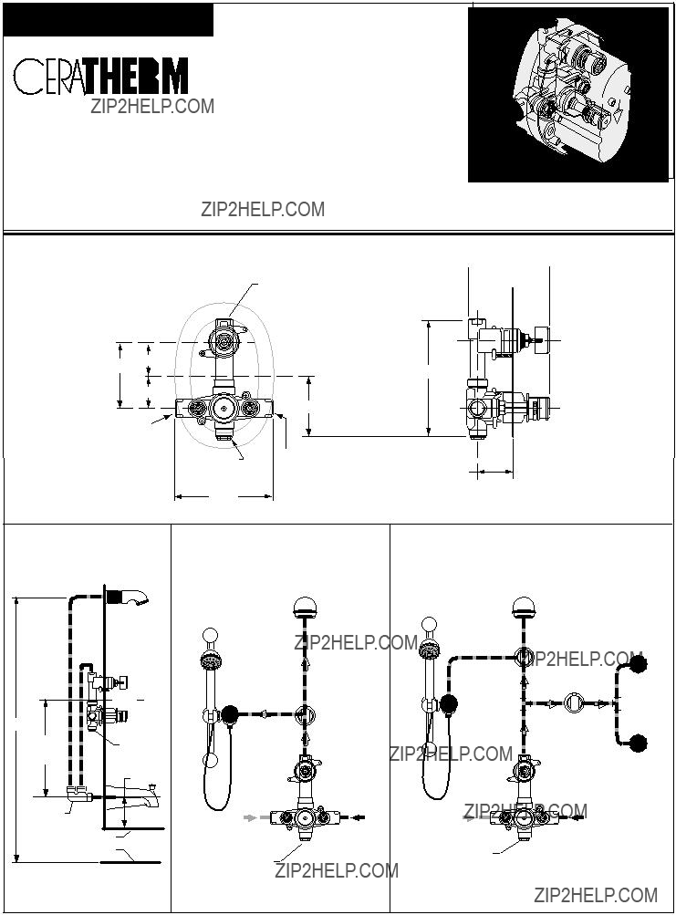
CONNECTIONS ARE: 3/4" NPT


3/4" NPT
SHOWER
Prepare water supplies per
Install VALVE at indicated height and depth. Make sure the "TOP" marking on the PLASTER GUARD is up.
IMPORTANT! INSTALL ANY REQUIRED SHUT OFF OR DIVERTER VALVES
INTO THE PIPING SYSTEM.
1
If the CHECK STOPS (4, 5) were removed during installation, ensure the hot and cold CHECK STOPS (4, 5) are not reversed. The hot CHECK STOP (4) has a red top and the cold CHECK STOP (5) has a blue top.
CHECK STOPS (4,5) are supplied in the open position. Closing using 5/32" (4 mm) hex wrench to pressure test and to check for leaks.
 MIXED
MIXED
COLD
TOP 
 PLUG TUB
PORT
5CHECK STOP (COLD BLUE)
To ???ush lines, remove the CHECK STOPS (4,5) and run water. If desired, the TEMPERATURE CONTROL UNIT can be removed. Reinstall CHECK STOPS (4,5) and CONTROL UNIT (6), if it was removed.
Remove PLASTER GUARD (2) if still installed. Turn on water supplies and check for leaks.
Reassemble PLASTER GUARD (2) and FINISH WALL.
Beware of Freezing. No water should remain in the MIXING VALVE if freezing is a possibility. Remove the CHECK STOPS (4,5) to completely drain the MIXER UNIT (1).
2TEMPERATURE ADJUSTMENT
Remove the TEMPERATURE LIMIT STOP (H shaped Black Plastic part). Reinstall it at the desired notch as indicated in the diagram to limit the maximum mixed water temperature to 104 F or 112 F.
For 100 F adjustment, turn the water supply on. Turn KNOB MOUNT until the spout temperature is 100 F. Check that arrow marking A on the KNOB MOUNT still points upward after adjusting the thermostat to 100 F. If not, pull out the RED LOCKING DEVICE. Remove KNOB MOUNT by pulling it towards you while standing directly in front of the valve.
Reinstall the KNOB MOUNT so that the arrow marking A points upwards.
Reinstall RED LOCKING DEVICE.
ARROW "B"
104
109
112
SECURING 
RING
RED LOCKING
DEVICE
BLACK
CLAMP
ARROW "A"
KNOB
MOUNT
3TRANSPOSED SUPPLY PIPING
OR BACK TO BACK INSTALLATION
Should the hot and cold water supply pipes have been transposed making adjustment impossible, proceed as follows:

 Shut off water supply.

 Remove handle and rim
 Remove check stops and
Important note: RED CHECK STOP is now on the right of the mixer body and the BLUE CHECK STOP is now on the left.
Turn the water supply back on and perform the temperature adjustment in step 2.
CHECK STOP
(BLUE TO RED)
CHECK STOP 


(RED TO BLUE)
M968480

3/4" CENTRAL THERMOSTAT
WITH VOLUME CONTROL
MODEL NUMBER
R540
CHECK STOP (COLD BLUE)
CARTRIDGE
HANDLE ADAPTER
CARTRIDGE SCREW
(SOLD SEPARATELY)