Copyright ?? 2006 Acer Incorporated
All Rights Reserved.
Acer Altos R910 Series
User???s Guide
Changes may be made periodically to the information in this publication without obligation to notify any person of such revision or changes. Such changes will be incorporated in new editions of this manual or supplementary documents and publications. This company makes no representations or warranties, either expressed or implied, with respect to the contents hereof and specifically disclaims the implied warranties of merchantability or fitness for a particular purpose.
Record the model number, serial number, purchase date, and place of purchase information in the space provided below. The serial number and model number are recorded on the label affixed to your server. All correspondence concerning your unit should include the serial number, model number, and purchase information.
No part of this publication may be reproduced, stored in a retrieval system, or transmitted, in any form or by any means, electronic, mechanical, photocopy, recording, or otherwise, without the prior written permission of Acer Incorporated.
Acer Altos R910
Model Name :
Part Number:
Purchase Date:
Place of Purchase:
Acer and the Acer logo are registered trademarks of Acer Inc. Other company???s product names or trademarks are used herein for identification purposes only and belong to their respective companies.
iii
Notices
FCC notice
Class A equipment
This device has been tested and found to comply with the limits for a Class A digital device pursuant to Part 15 of the FCC Rules. These limits are designed to provide reasonable protection against harmful interference when the equipment is operated in a commercial environment. This equipment generates, uses, and can radiate radio frequency energy, and if not installed and used in accordance with the instructions, may cause harmful interference to radio communications. Operation of this equipment in a residential area is likely to cause harmful interference, in which case the user will be required to correct the interference at personal expense.
However, there is no guarantee that interference will not occur in a particular installation. If this device does cause harmful interference to radio or television reception, which can be determined by turning the device off and on, the user is encouraged to try to correct the interference by one or more of the following measures:
???Reorient or relocate the receiving antenna
???Increase the separation between the device and receiver
???Connect the device into an outlet on a circuit different from that to which the receiver is connected
???Consult the dealer or an experienced radio/television technician for help
Notice: Shielded cables
All connections to other computing devices must be made using shielded cables to maintain compliance with FCC regulations.
Notice: Peripheral devices
Only peripherals (input/output devices, terminals, printers, etc.) certified to comply with the Class A limits may be attached to this equipment. Operation with noncertified peripherals is likely to result in interference to radio and TV reception.
iv
Caution! Changes or modifications not expressly approved by the manufacturer could void the user???s authority, which is granted by the Federal Communications Commission, to operate this server.
Use conditions
This part complies with Part 15 of the FCC Rules. Operation is subject to the following two conditions: (1) this device may not cause harmful interference, and (2) this device must accept any interference received, including interference that may cause undesired operation.
Notice Canadian users
This device does not exceed the Class A limits for radio noise emissions from digital apparatus set out in the interference-causing equipment standard entitled ???Digital Apparatus??? ICES-003 of the Canadian Deparmment of Communications.
Laser compliance statement
The DVD-ROM drive in this server is a laser product. The optical drive???s classification label (shown below) is located on the drive.
CLASS 1 LASER PRODUCT
CAUTION: INVISIBLE LASER RADIATION WHEN OPEN. AVOID EXPOSURE TO BEAM.
v
Important safety instructions
Read these instructions carefully. Save these instructions for future reference.
1Follow all warnings and instructions marked on the product.
2Unplug this product from the wall outlet before cleaning. Do not use liquid cleaners or aerosol cleaners. Use a damp cloth for cleaning.
3Do not use this product near water.
4Do not place this product on an unstable cart, stand, or table. The product may fall, causing serious damage to the product.
5Slots and openings on the back or bottom side of the chassis are provided for ventilation; to ensure reliable operation of the product and to protect it from overheating, these openings must not be blocked or covered. The openings should never be blocked by placing the product on a bed, sofa, rug, or other similar surface. This product should never be placed near or over a radiator or heat register, or in a built-in installation unless proper ventilation is provided.
6This product should be operated from the type of power indicated on the marking label. If you are not sure of the type of power available, consult your dealer or local power company.
7Do not allow anything to rest on the power cord. Do not locate this product where persons will walk on the cord.
8If an extension cord is used with this product, make sure that the total ampere rating of the equipment plugged into the extension cord does not exceed the extension cord ampere rating. Also, make sure that the total rating of all products plugged into the wall outlet does not exceed the fuse rating.
9Never push objects of any kind into this product through the chassis slots as they may touch dangerous voltage points or short out parts that could result in a fire or electric shock. Never spill liquid of any kind on the product.
10Do not attempt to service this product yourself, as opening or removing covers may expose you to dangerous voltage points or other risks. Refer all servicing to qualified service personnel.
11Unplug this product from the wall outlet and refer servicing to qualified service personnel under the following conditions:
a When the power cord or plug is damaged or frayed b If liquid has been spilled on the product
c If the product has been exposed to rain or water
vi
dIf the product does not operate normally when the operating instructions are followed. Adjust only those controls that are covered by the operating instructions since improper adjustment of other controls may result in damage and will often require extensive work by a qualified technician to restore the product to normal condition.
eIf the product has been dropped or the chassis has been damaged
fIf the product exhibits a distinct change in performance, indicating a need for service.
12Replace the battery with the same type as the product's battery we recommend. Use of another battery type may present a risk of fire or explosion. Refer battery replacement to a qualified service technician.
13Warning! Batteries may explode if not handled properly. Do not disassemble or dispose of them in fire. Keep them away from children and dispose of used batteries promptly.
14Use only the proper type of power supply cord set (provided in your accessories box) for this unit. It should meet the following criteria:
???An IEC 320 C13 connector to plug into the power supply on the server.
???For North America or similar electrical distribution systems: UL listed/ CSA certified, 16/3 type SJT/SO, with NEMA 6-15P SPT-2, or equivalent attachment plug.
???For Europe or similar electrical distribution systems: VDE certified or HAR rated 250V, 3 x 1.0mm2 minimum conductor size, rather for no less than the product ratings.
???Maximum length is 14.76 feet (4.5 meters).
The Acer Altos R910 is a rack optimized 64-bit Intel Xeon MP processor-based server system. The system features redundant memory, networking, hot-plug PCI slots, standard-based server management, and server-oriented embedded I/O. Remote monitoring and management functions are also included, providing a new level of user tools for server administration.
This chapter provides a brief overview of the system hardware, including illustrations and component identification.
3
Features summary
Listed below are the system???s key features:
Processor
???Supports one to four physical processors
???Dual-core Intel?? Xeon??? processors 7000 sequence
???64-bit Intel Xeon processors MP with 1 MB L2 cache
???667 or 800 MHz front side bus
???Hyper-Threading Technology
???Extended Memory 64-bit Technology
???Demand-Based Switching for power savings
???Execute -Disable Bit for hardware support of security features
Chipset
???Intel E8501 chipset (north bridge)
???Support dual front side bus
???Support for hot-plug memory
???Intel IOP332 storage I/O processor
???Includes Intel XScale Technology works in conjunction with the LSI Logic 53C1030 Ultra320 SCSI controller to support optional integrated SCSI hardware RAID
???Intel 81801EB I/O Controller Hub 5 (south bridge)
Memory subsystem
???Supports up to 64GB of DDR2-400 MHz (PC2-3200) registered ECC memory modules
???Supports one to four hot-plug memory boards
???Each memory board supports:
-Four DIMM slots
-DDR2 channels with two DIMMs per channel
-Connection through x16 PCI-Express slots
???Memory reliability, availability, and serviceability (RAS) features
???Memory mirroring
???Memory RAID
???Memory sparing
???Memory hot-plug
???x8 SDDC (Single Device Data Correction) for memory error detection and correction
Media storage
???One 5.25-inch device bay supports:
???AIT2 tape drive
???LTO-2 half-height tape drive
???Up to five hot-plug Ultra320 SCSI hard disk drives
SCSI controller
???LSI Logic 53C1030 LVD SCSI controller
???Dual independent Ultra320 SCSI interfaces (internal)
Integrated hardware RAID (optional)
???Supports RAID levels 0, 1, 5, and 10
???Requires RAID activation key (iButton)
???Requires DDR2-400 registered ECC DIMM for RAID cache
???Supports RAID BBU (Battery Backup Unit). Available as an upgrade option.
Note: After installing the iButton and RAID cache DIMM, the system BIOS setup allows you to enable the hardware RAID solution. For detailed installation instructions, see ???Configuring integrated SCSI hardware RAID components??? on page 79.
You can also install a RAID BBU to improve fault tolerance by enhance by protecting data in the RAID cache in the event of power failure. For more information on how to install a RAID BBU, see ???Installing the RAID BBU??? on page 85.
5
Serial ATA port
???One SATA port (reserved for slim-type DVD drive)
Networking
???Broadcom BCM5704C Gigabit Ethernet Controller with dual ports
PCI I/O
???One hot-plug x8 PCI Express slot
???Three hot-plug x8 PCI Express slots (with x4 throughput)
???One hot-plug 133 MHz, 64-bit PCI-X slot
???Two non hot-plug 100 MHz, 64-bit PCI-X slots
Note: The PCI hot-plug function allows the removal of a standard PCI adapter from the system without stopping the software or powering down the unit.
Graphic interface
???ATI Radeon?? 7000 video controller with 16MB SDRAM
Baseboard Management Controller
???Integrated Acer BMC module
???IPMI (Intelligent Platform Management Interface) 2.0 compliant
???Supports ARMC/3 (Acer Remote Management Card/3) (optional)
I/O ports
???Front
???VGA/monitor port
???Three USB 2.0 ports
???Rear
???Serial port
???External SCSI connector (optional)
???VGA/monitor port
???Two USB 2.0 ports
???Two Gigabit LAN ports (RJ-45)
???Server management port (RJ-45) 1
Operating system and software
???Operating system options:
???Microsoft?? Windows?? Server 2003, x64 Edition
???Microsoft Windows Server 2003
???Red Hat Enterprise Linux 4.0
???Red Hat Enterprise Linux 4.0, EM64T
???SUSE?? Linux Enterprise Server 9.0
???SUSE Linux Enterprise Server 9.0, EM64T
???ASM (Acer Server Manager) 2
???Easy Build (includes SCSI RAID Configuration Utility) 2
Power supply
???Two 220-volts, 1470-watt hot-swap (1+1) redundant power supply modules
System fan
???Two hot-swap redundant system fan modules
???Two redundant (1+1) fans in each system fan module
1Reserved for remote management of server. This requires installation of an ARMC/3.
2For more information on how to install and use ASM and Easy Build utilities, refer to the manual on the EasyBUILD DVD.
7
External and internal structure
Front bezel
The front bezel provides an interface for system management via status LED indicators. The status LEDs on the bezel mirrors the LEDs on the front panel, indicating HDD activity, LAN1 and LAN2, system status/ fault, power, and ID status. The bezel is detachable to allow access to the external drive bays, serial and USB connectors, LED indicators, and the power, reset, and system ID buttons. A summary of the indicators and components behind the bezel is given in the succeeding section.
For details on how to remove the front bezel, see ???Removing the front bezel??? on page 35.
9
* The hot-swap system fan assembly indicator lights up amber when a fan module fails.
Front panel control button functions
Below table lists the functions of the front panel control buttons.
Front panel LED indicators
Below table lists the LED states on the front panel.
???HDD is powered on and rebuilding RAID.
???HDD is powered on and has a fault condition.
B1 Hot-plug PCI Express x8 slot
B2 Hot-plug PCI-X 133MHz slot
B3 Hot-plug PCI Express x8 slot (with x4 throughput)
B4 Hot-plug PCI Express x8 slot (with x4 throughput)
B5 Hot-plug PCI Express x8 slot (with x4 throughput)
B6 PCI-X 100MHz slot
B7 PCI-X 100MHz slot
H1, Hot-swap power supply H2 module DC input power
connectors
FGigabit LAN ports (10/100/1000 Mbps)
*Reserved for remote management of server. This requires installation of an ARMC/3 (Acer remote management card/3).
Rear panel LED indicators
Below table lists the LED states on the rear panel.
17
System boards
Mainboard
The mainboard becomes accessible once you open the system. It should look like the figure shown below.
* Reserved for remote management of server. This requires installation of an ARMC/3 (Acer remote management card/3)
Hot-plug memory board
* Press this button to perform a hot-insertion or hot-removal of a memory board.
21
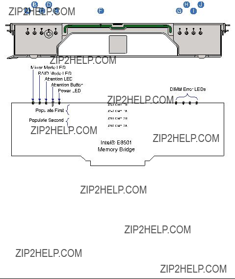
Memory board LED indicators
The hot-plug memory board has LEDs indicating the configuration and status of the DIMMs installed on it.
This chapter gives you instructions on how to set up the system. Procedures on how to connect peripherals are also explained.
25
Setting up the system
Pre-installation requirements
Selecting a site
Before unpacking and installing the system, select a suitable site for the system for maximum efficiency. Consider the following factors when choosing a site for the system:
???Near a grounded power outlet
???Clean and dust-free
???Stable surface free from vibration
???Well-ventilated and away from sources of heat
???Secluded from electromagnetic fields produced by electrical devices such as air conditioners, radio and TV transmitters, etc.
Checking the package contents
Check the following items from the package:
???Acer Altos R910 system
???Acer EasyBUILDTM
???Acer Altos R910 accessory box
If any of the above items are damaged or missing, contact your dealer immediately.
Save the boxes and packing materials for future use.
Connecting peripherals
Caution! The server operates on 220 VDC only. Do not connect the system to an incorrect voltage source.
Refer to the illustration below for specific connection instructions on the peripherals you want to connect to the system.
Note: Consult the operating system manual for information on how to configure the network setup.
27
Turning on the system
After making sure that you have properly set up the system and connected all the required cables, you can now power on the system.
To power on the system, press the power button on the front control panel.
The system starts up and displays a welcome message on the monitor. After that, a series of power-on self-test (POST) messages appears. At the BIOS splash screen, the System Options menu can be accessed by pressing a key on the keyboard. For more information on how to use the System Options menu, see ???System options menu??? on page 90.
Note: If the system does not turn on or boot after pressing the power button, go to the next section for the possible causes of the boot failure.
The POST messages indicate if the system is running well or not. If the POST finds any problems, the system will emit a beep code followed by an error message displayed on the monitor. Aside from the POST messages, you can determine if the system is in good condition by checking if the following occurred:
???Power indicator on the front panel lights up (green)
???Num Lock, Caps Lock, and Scroll Lock indicators on the keyboard light up
Power-on problems
If the system does not boot after you have applied power, check the following factors that might have caused the boot failure.
???The external power cable may be loosely connected.
Check the power cable connection from the power source to the power cable socket on the rear panel. Make sure that the cable is properly connected to the power source and to the power cable socket.
???No power comes from the grounded power outlet. Have an electrician check your power outlet.
???Loose or improperly connected internal power cables.
Check the internal cable connections. If you are not confident to perform this step, ask a qualified technician to assist you.
Warning! Make sure all power cords are disconnected from the electrical outlet before performing this task.
???The ARMC/3 or BMC module is not installed in the server, or not properly seated.
Check the ARMC/3 or BMC module connection. Make sure the ARMC/3 or BMC module is properly connected to the mainboard. For more information on how to install the ARMC/3 or BMC module, see ???Installing the ARMC/3 or BMC module??? on page 77.
Note: If you have gone through the preceding actions and the system still fails to boot, ask your dealer or a qualified technician for assistance.
29
Configuring the system OS
The Altos R910 comes with Acer EasyBUILDTM that allows you to conveniently install your choice of operating system. To start using EasyBUILD, follow the steps below.
1Locate the EasyBUILD DVD included in the system package.
2With the system turned on, gently press the CD-ROM drive Stop/ Eject button.
3When the disc tray slides open, insert the EasyBUILD DVD with the label or title side of the disc facing upward.
Note: When handling the disc, hold it by the edges to avoid smudges or fingerprints.
4Gently press the disc down to make sure that it is properly inserted.
Caution! While pressing the disc, be careful not to bend the disc tray. Make sure that the disc is properly inserted before closing the disc tray. Improper insertion may damage both the disc and the CD-ROM drive.
5Gently press the drive Stop/Eject button again to close the disc tray.
6The Acer EasyBUILD sequence begins. Follow all onscreen instructions.
For more information, refer to the EasyBUILD Installation guide.
Note: EasyBUILD DVD supports Windows Server 2003 and Red Hat Linux operating system only.
Windows or Linux OS CD is needed when you install the OS with the EasyBUILD DVD.
Turning off the system
There are two ways by which you can turn off the server. These include:
???If you are using a Windows OS on your server, you can turn off the server by clicking the Start button on the Windows taskbar, point to Shut Down..., select Shut down from the drop-down window then click on OK. You can then turn off all peripherals connected to your server.
If you are using another OS, refer to the OS documentation for instructions on how to shut down the OS.
???If you cannot shut down the server, press the power button for at least four seconds. Quickly pressing the button may put the server in a Suspend mode only.
This chapter discusses the precautionary measures and installation procedures you need to know to upgrade the system.
33
Installation precautions
Before you install any server component, we recommend that you read the following sections. These sections contain important ESD precautions along with pre-installation and post-installation instructions.
ESD precautions
Electrostatic discharge (ESD) can damage the processor, disk drives, expansion boards, motherboard, memory modules and other server components. Always observe the following precautions before you install a server component:
1Do not remove a component from its protective packaging until you are ready to install it.
2Wear a wrist grounding strap and attach it to a metal part of the server before handling components. If a wrist strap is not available, maintain contact with the server throughout any procedure requiring ESD protection.
Pre-installation instructions
Perform the steps below before you open the server or before your remove or replace any component:
1Turn off the system and all the peripherals connected to it.
2Unplug all cables from the power outlets.
3Place the system unit on a flat, stable surface.
4Open the system according to the instructions on page 35.
5Follow the ESD precautions described in this section when handling a server component.
6Remove any hardware structure or cable that block access to the component you must replace or upgrade.
See the following sections for specific installation instructions on the component you want to install.
Warning! Failure to properly turn off the server before you start installing components may cause serious damage. Do not attempt the procedures described in the following sections unless you are a qualified service technician.
Post-installation instructions
Perform the steps below after installing a server component:
1See to it that all components are installed according to the described step-by-step instructions.
2Reinstall all hardware structure or cable that have been previously removed.
3Reinstall the top cover.
4Reinstall the front bezel.
5Connect the necessary cables.
6Turn on the system.
35
Opening the server
Caution! Before you proceed, make sure that you have turned off the system and all peripherals connected to it. Read the ???Pre- installation instructions??? on page 33.
You need to open the server before you can install additional components. The front bezel and top cover are removable to allow access to the system???s internal components. Refer to the following sections for instructions.
Removing the front bezel
Grasp the front bezel at outer edge and pull straight out.
Installing the front bezel
Slide the front bezel onto the chassis.
Removing the top cover
1Observe the ESD precautions and pre-installation instructions described on page 33.
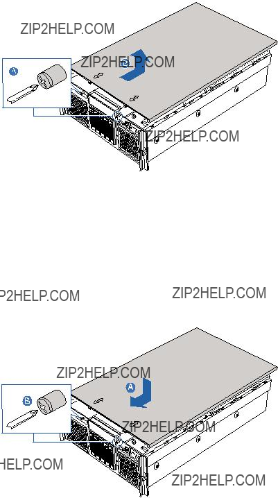
2Loosen the two captive screws located on the faceplate of the chassis (A). See illustration on page 37.
3Slide the top cover toward the back of the chassis until the tabs on the cover disengage with the slots on the chassis.
37
4Lift the top cover away from the server and put it aside for reinstallation later (B).
Installing the top cover
1Observe the ESD precautions and pre-installation instructions described on page 33.
2Place the top cover on the chassis so that the tabs on the cover align with the slots on the chassis (A).
3Slide the top cover toward the front of the chassis until it is fully closed.
4Tighten the captive screws on the faceplate of the chassis (B).
Removing the CPU air baffle
You will need to remove the CPU air baffle to perform the following procedures:
???Removing and installing a heat sink
???Removing and installing a CPU
???Removing and installing a DVD drive
To remove the CPU air baffle
1Observe the ESD precautions and pre-installation instructions described on page 33.
2Insert your fingers into the holes on the top of the baffle (A).
3Pull the baffle up and back to disengage the baffle from the two sheet-metal tabs on the front of the baffle.
4Lift the baffle from the chassis (B).
39
Installing the CPU air baffle
1Observe the ESD precautions and pre-installation instructions described on page 33.
2Insert the front of the CPU air baffle under the two metal tabs at the front of the baffle, just below the SCSI backplane board. One tab is located on each side of the chassis.
3Lower the rear of the baffle into place, making sure the guides on each side of the air baffle will correctly engage in the left and right chassis slots.
4Push down the air baffle to the two locations where the word Memory is printed on the air baffle.
5Observe the post-installation instructions described on page 34.
Removing the center brace
You will need to remove the center brace to remove and install an optional processor core VRM.
To remove the center brace
1Observe the ESD precautions and pre-installation instructions described on page 33.
2Slide the chassis at each side of the chassis to the unlock position
(A).
3Lift the center brace from the chassis (B).
41
Installing the center brace
1Observe the ESD precautions and pre-installation instructions described on page 33.
2Slide the center brace into position in the chassis (A).
3Slide the latches at each side of the chassis to the locked position
(B).
4 Observe the post-installation instructions described on page 34.
Removing a memory board air baffle
You will need to remove the memory board air baffle to perform the following procedures:
???Removing and installing a memory board
???Removing and installing a PCI card
To remove the memory board air baffle
1Observe the ESD precautions and pre-installation instructions described on page 33.
2Insert your fingers into the two holes on the top of the memory board air baffle, then push the tab (A).
3Lift the memory board air baffle from the server (B).
43
Installing a memory board air baffle
1Observe the ESD precautions and pre-installation instructions described on page 33.
2Insert the memory board air baffle into the memory board slot with arrow on the tab pointing to the right. The memory air baffle will lock into the memory board slot.
3 Observe the post-installation instructions described on page 34.
Configuring hot-pluggable components
Hot-pluggable components are the components that can be removed and replaced while the system is powered on. For this server model, it refers to the following:
???Hard disk drives
???System fan assembly
???Power supply
???Memory board
???PCI cards with OS hot-plug interface
45
Hard disk drives
The server???s hard disk drive bay supports five hot-plug SCSI drives. Use only Acer-qualified HDDs. To purchase an HDD, contact your local Acer representative.
Caution! To ensure proper airflow and server cooling, all drive bays must contain either a carrier with a hard drive installed in it or a hard disk carrier cover.
Determining drive status
Each HDD carrier features a dual-color LED indicator to display the hard drive status. If you are replacing a failed HDD, determine which drive has failed by checking the drive status LED. For more information on how to determine the drive status, refer to ???Front panel LED indicators??? on page 10.
Removing a HDD
1Observe the ESD precautions described on page 33.
2If you are removing a failed HDD, determine which drive has failed by checking the drive status LED.
3Press the green HDD carrier latch (A).
4Pull the lever to remove the HDD carrier from the chassis (B).
5Place the HDD carrier on a clean, static-free work surface.
6If you are replacing a hard disk, remove the four screws that secure the hard disk to the HDD carrier, then remove the disk from the HDD carrier.
Keep the screws for later HDD installation.
Installing a HDD
Note: To puchase a HDD carrier, contact your local Acer representative.
1Perform steps 1 to 4 of the ???Removing a HDD??? on page 45.
2Remove the four screws that secure the air baffle to the HDD carrier (A).
3Remove the air baffle from the HDD carrier (B).
4Save the air baffle and screws for later use.
5Install a hard disk on the HDD carrier, then secure it with the four screws (A) that came with the HDD carrier (B).
6With the lever still extended, slide the HDD carrier all the way into the drive bay.
47
7Use the lever to push the HDD carrier until it docks into place (A), then close the HDD carrier lever (B).
System fan assembly
The system has two cooling fan assemblies ??? two fan modules each ??? located on the front panel. Each assembly has an amber LED to indicate a failed fan condition. If the amber LED is on, the fan assembly needs to be replaced. The LED remains off during normal operation.
Removing the system fan assembly
Caution: System fan assembly hot-swap operations should be performed only if a failure occurs in the system fan assembly.
1Observe the ESD precautions described on page 33.
2Locate the fan assembly you are replacing. If a fan in the assembly has failed the amber LED will be lit (A).
3Press the green button on the front of the fan assembly to release the handle (B).
4Use the handle to pull the fan from the system (C).
Installing the system fan assembly
Warning! To ensure proper system cooling, the replacement of a failed system fan module should be completed within one minute.
1If a system fan assembly is installed in the fan bay, perform steps 1 to 3 of the ???Removing the system fan assembly??? section.
2Slide the new fan into the fan bay (A).
3Push the handle closed until it clicks into place (B).
49
Power supply
The server has two hot-swap power supply module bays on the rear panel that accept hot-swap redundant power supply modules. The system ships out with two power supply modules installed. A redundant power configuration enables a fully-configured system to continue running even if one power supply module fails.
WARNING! To reduce the risk of personal injury or damage to the equipment, the installation of power supply modules should be referred to individuals who are qualified to service server systems and are trained to deal with equipment capable of generating hazardous energy levels.
WARNING! To reduce the risk of personal injury from hot surfaces, observe the thermal labels on each power supply module. You can also consider wearing protective gloves.
WARNING! To reduce the risk of personal injury from electric shock hazards, do not open the power supply modules. There are no serviceable parts inside the module.
Caution! Electrostatic discharge can damage electronic components. Make sure that you are properly grounded before handling a power supply module.
Caution! Due to chassis airflow disruption, a power supply bay should never be vacant for more than two minutes when the server is powered on. Exceeding five minutes might cause the system to exceed the maximum acceptable temperature and possibly damage the system components.
Caution! The system does not support running with only one power supply. To prevent chassis airflow disruption, a power supply bay should never be vacant for more than two minutes. Exceeding the time may cause the system to exceed the maximum acceptable temperature and possibly damage system components.
Caution! The system operating voltage range is 200 to 240 VDC. Do not plug the power cord into an incorrect voltage voltage source.
Removing a power supply
Caution: Power suppy hot-swap operations should be performed only if a failure occurs in the power supply.
1Observe the ESD precautions described on page 33.
2Remove the DC power cord from the power supply.
3Loosen the thumbscrew on the latch to unlock the power supply handle (A).
4Open the handle on the power supply (B).
5Pull the power supply from the chassis and set it on a clean, static- free surface (C).
6 Install a filler panel.
Installing a power supply
Caution! To ensure proper system cooling, the replacement of failed power supply shoule be completed within two minutes.
1Observe the ESD precautions described on page 33.
2Remove the filler panel from the empty power supply bay, if installed.
3With the handle in the open position, push the power supply in the bay fully (A).
51
4Rotate the handle to the closed position (B).
5Tighten the thumbscrew to secure the power supply (C).
6Plug the power cord into the DC receptacle on the power supply.
7Verify that the LEDs on the power supply are functioning. Refer to the ???Rear panel LED indicators??? on page 14 for more information.
Memory board
The memory boards in the server connect to the mainboard through the x16 PCI Express slots or memory board slots A, B, C, and D. Refer to ???Mainboard??? on page 17 for the location of the memory board slot. Up to four memory boards can be installed in the server. Each memory board has four DIMM slots that support two DDR2 channels, with two DIMMs per channel. The memory boards support both single-rank and double-rank, registered ECC DIMMs.
The memory boards can be configured in a redundant or non- redundant configuration. Memory boards configured using RAID or mirroring are in redundant configuration. If a memory board that is configured in a redundant configuration has a DIMM or memory board fault, the memory board and/or DIMM containing the fault can be removed and replaced while the system is powered on. Memory boards that are configured in a non-redundant configuration (including memory boards configured with spare memory) must not be removed while the system is powered on.
Caution! Do not attempt to hot-remove or hot-add a memory board in a non-redundant configuration. If your server is not configured in the BIOS setup utility for maximum compatibility, memory RAID, or memory mirroring, you must power down your server before removing or installing any memory board or DIMMs. For instructions, see ???Cold removal of memory board instructions??? described on page 70 and ???Cold insertion of a memory board instructions??? described on page 71.
Memory board replacement options
The server include the following memory board replacement options:
???Memory hot-replace - While the system is in operation and configured with a RAID or mirroring configuration, you can replace a failed memory board. The replacement board must include identical memory capacity. The system will test, initialize, and rebuild the data on the memory board and then include this board in the system memory configuration. The activity is transparent to the OS. For instructions on how to hot-replace the memory board, see ???Removing a hot-plug memory board??? on page 53.
???Memory hot-add - You can increase the memory capacity of the system while the OS is active and if it is in a RAID or mirror configuration. If your server is in a RAID configuration, you can remove only one memory board at a time to upgrade the memory or replace the memory board. In a mirror configuration, you can add an additional two mirrored memory boards. In a maximum compatibility configuration, a new memory board can be added to an empty slot. When the initialization is complete, the operating system is informed of the new memory. For instructions on how to hot-add the memory board, see ???Installing a hot-plug memory board??? on page 54.
???Memory cold-plug operation - If your server is not in a RAID or mirror configuration, you must turn off the server to add or replace the memory board. To replace or remove a memory board using cold-plug operation, see ???Installing a memory board??? on page 71 and ???Removing a memory board??? on page 70.
53
Removing a hot-plug memory board
Note: If you remove a memory board from the server, you must either replace it with a new memory board or install a memory board air baffle.
1Observe the ESD precautions described on page 33.
2Press the attention button on the memory board. The power LED will begin to flash. Refer to ???Memory board LED indicators??? on page 21 for the location of the power LED.
3After the hot-plug attention LED stops flashing, make sure the power LED for the memory board is also off.
Caution! Do not attempt to remove any memory board while any of the LEDs are either on or blinking. If the attention LEDs do not turn off, your configuration may not support hot-plug memory board activity. For instructions on non-hot-plug memory board maintenance, see ???Cold removal of memory board??? and ???Cold insertion of a memory board???.
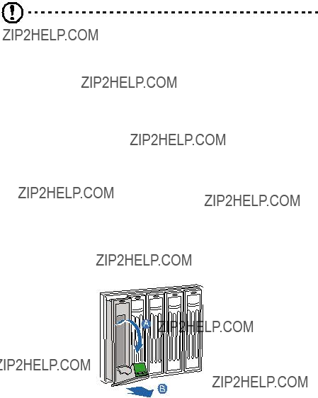
4Once all the board LEDs are off, press the latch on the memory board handle to release the handle (A) and lift the handle up (B).
5Lift the memory board from the server (C).
6Install a memory board or memory board air baffle. For instructions on how to install a memory board, refer to section below. For instructions to install a memory board air baffle, refer to ???Installing a memory board air baffle??? on page 43.
7Observe the post-installation instructions described on page 34.
Installing a hot-plug memory board
1Observe the ESD precautions described on page 33.
2Locate an empty memory board slot.
3If necessary, remove the memory board air baffle. Perform instructions described in ???Removing a memory board air baffle??? on page 42.
4Add or replace memory DIMMs as needed. For instructions, see ???Installing DIMMs??? on page 73 and ???Removing DIMMs??? on page 75.
5Ensure the handle on the memory board is in the open position.
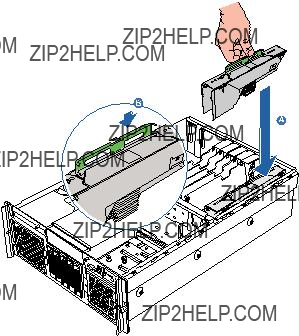
6Align the board edges with the card guides and slide the memory board into the memory board slot (A).
7Push the handle down until it is in the locked position (B).
8 Observe the post-installation instructions described on page 34.
55
The BIOS setup utility executes a memory test prior to configuring the memory in POST and when a memory board is inserted into the system during a memory hot-removal or hot-add operation.
If a DIMM fails the memory test, an LED will light on the memory board to identify the location of the bad DIMM and the DIMM bank will be disabled. The failed DIMM is logged onto the System Event Log (SEL). BIOS setup utility will disable the DIMM and/or the memory board. Upon subsequent reboots, this memory is not initialized unless the BIOS setup option ???Reset all system memory??? or ???Retest board memory??? is selected. Refer to ???4 BIOS setup??? on page 87 for more information.
PCI card
Caution! Only PCI add-in cards in PCI slots 1 through 5 are hot-pluggable. If you are installing or removing a PCI card from PCI slot 6 or 7, see page 76 for more information.
Cards can be hot-plugged in PCI slots 1 through 5. You can remove and replace a PCI card with OS hot-plug interface.
Removing hot-plug PCI card
To remove a hot-plug PCI card with OS hot-plug interface:
1Observe the ESD precautions described on page 33.
2If you are using a Microsoft Windows operating system, double- click the Unplug/Eject icon in the taskbar to open the Unplug or Eject Hardware menu.
3Select the device to be removed and click Stop.
4Make sure that the power LED on the rear of the PCI slot is turned off before disconnecting any cables attached to the card.
5Rotate the slot retention latch on the rear of the card slot upward
(A).
6Pull up the card to remove it (B).
7Store the card in an antistatic protective wrapper.
8Install the slot cover over the empty slot, then rotate the retention latch downward (C).
9 Observe the post-installation instructions described on page 34.
Installing a hot-plug PCI card
1If your server is operating, use your OS to power down the PCI slot.
2Observe the ESD precautions described on page 33.
3Locate an empty expansion slot on the mainboard.
4Rotate the slot retention latch on the rear of the card slot upward.
5Pull up the slot cover.
6Remove the PCI add-in board from its protective packaging.
7Align the card in the empty slot.
8Insert the card into the selected slot. Make sure that the card is properly seated.
9Rotate the retention latch downward.
10Connect any required cable to the card.
11When using the hot-plug PCI card with OS hot-plug interface:
???Wait for the software user interface to appear on your monitor and then confirm the device to be enabled.
???Wait for the power LED to turn on.
57
Configuring cold-pluggable components
Cold-pluggable components are the components that require the system to be powered down before you can remove or replace them. The cold-pluggable components installed in the server include:
???DVD drive
???5.25-inch drive
???Processor
???Processor core VRMs
???Memory board
???DIMM modules
???PCI card
???ARMC/3 or BMC module
DVD drive
Removing the DVD drive
1Observe the ESD precautions and pre-installation instructions described on page 33.
2Disconnect the power and SATA cables from the SATA-to-IDE converter board on the rear of the media device (A).
3Press the blue release latch on the media device carrier (B).
4Slide the media device from the front opening in the faceplate of the system (C).
Installing the DVD drive
1Observe the ESD precautions and pre-installation instructions described on page 33.
2If necessary, remove the old DVD drive. See previous section.
59
3Lift the rear right corner of the media device to remove it from the carrier (A) and (B).
4Remove the SATA-to-IDE converter board (C).
5Remove the new drive from its protective packaging.
6Attach the SATA-to-IDE converter board to the media device.
7Install a new media device into the carrier.
8Slide the carrier into the front opening in the chassis.
9Plug the SATA and power cables into the converter board.
10Observe the post-installation instructions described on page 34.
5.25-inch drive
The 5.25-inch drive bay allows you to install additional drives such as another backup hard drive, CD-ROM drive, or a tape drive. These options provide the system with additional storage capacity.
Installing a 5.25-inch drive
1Observe the ESD precautions and pre-installation instructions described on page 33.
2Push the tabs on both sides of the carrier filler panel (A).
3Hold the tabs in while pulling the carrier filler panel from the bay
(B).
4Remove the screws that attach the slide rails to the filler panel.
5Attach the slide rails to the device, then secure it with screws you removed earlier.
6Attach the Y-power cable to the rear of the device.
61
7Slide the 5.25-inch peripheral device into the server until it clicks into place.
8 Observe the post-installation instructions described on page 34.

Processor
The server supports up to four processors, the following models are supported:
???dual-core Intel Xeon processor 7000 sequence
???64-bit Intel Xeon processor MP with 1 MB L2 cache
CPU upgrading guidelines
When installing CPUs the following must be observed:
???Use only Acer-qualified CPUs.
???Each CPU socket include a CPU and heat sink combination.
???CPUs should have identical FSB, cache, and speed.
???CPUs must be installed in sequential order beginning with the CPU_1 socket.
???If you are installing an additional CPU, read the information on ???Processor core VRM requirements??? on page 66 to determine if you need to add any VRMs and follow the instructions listed on the requirements.
???If you are removing a CPU, but not installing replacement processor, read the information on ???Processor core VRM requirements??? on page 66 to determine if you need to remove any VRMs and follow the instructions listed on the requirements.
Removing a CPU
The system may have from one to four CPUs installed on the mainboard. If you are replacing a CPU on the system, the heat sink must be removed.
Important: Before removing a CPU from the mainboard, make sure to create a backup file of all important data.
1Observe the ESD precautions and pre-installation instructions described on page 33.
Warning! The heat sink becomes very hot when the system is on. NEVER touch the heat sink with any metal or with your hands.
63
2If necessary, remove the CPU air baffle. Perform instructions described in ???Removing the CPU air baffle??? on page 38.
3Locate the CPU you want to remove.
4Loosen the four screws on the heat sink.
5Lift the heat sink to remove it.
6Place the heat sink upside down on a flat surface.
Note: Wipe off the thermal grease from both the heat sink and processor using an alcohol pad.
7Pull the CPU socket retainer lever to the fully open, upright position.
Store it in an anti-static bag.
Installing a CPU
1Perform steps 1 to 3 of the ???Removing a CPU??? section.
2If a heat sink is installed, remove it.
3Pull the CPU socket retainer lever to a fully open position.
4 Remove the CPU from its protective packaging.
65
5Position the CPU over the socket, matching the two triangle markers (A) and lining up the CPU pins with the socket (B).
6 Press the retainer lever down to lock the CPU in place.
7If the heat sink does not have thermal grease on the bottom, apply thermal grease to the heat sink base.
8Set the heat sink on the processor, aligning the four screws in the heat sink with the screw sockets in the chassis.
9Tighten the screws approximately one full turn at a time until each is evenly tightened. Do not fully tighten one screw at a time.
10Install the processor VRMs and processor core VRMs as necessary. To determine requirements, see ???Processor core VRM requirements??? on page 66.
11Reinstall the CPU air baffle. See ???Installing the CPU air baffle??? on page 39.
12Observe the post-installation instructions described on page 34.
Processor core VRMs
Use processor core 10.2 VRMs with processors installed in CPU sockets 3 and 4.
Processor core VRM requirements
This server requires the installation of VRMs when upgrading the CPU in CPU sockets 3 and 4.
10.2 VRM for CPU3
10.2 VRM for CPU4
CPU3
CPU4
CPU2
CPU1
Refer to the configuration label on the inside of the chassis top cover for the locations of these VRMs. Contact your local Acer representative for specific VRM requirements. As an overview, the following generic VRM rules apply:
67
Removing the processor core VRM
Note: The two processor core VRMs are located under the center brace.
1Observe the ESD precautions and pre-installation instructions described on page 33.
2Remove the memory boards or memory air baffles from DIMM slots C and D. See ???Cold Removal of Memory Board??? on page 70 and ???Removing a memory board air baffle??? on page 42.
3Remove the fourth processor core VRM.
Warning! The processor 4 VRM baffle must be installed to maintain proper system airflow, even though you may not have installed a VRM.
(1)Push down at the top of the baffle to unlatch it (A).
(2)Pull the cover out at an angle (B).
4 Press the holding clips on both sides of the VRM connector (A).
5 Gently pull the VRM upward to remove it from the socket (B).
Processor 3 VRMProcessor 4 VRM
6 Observe the post-installation instructions described on page 34.
Installing a processor core VRM
Caution! The processor core VRM connector is slotted to ensure proper installation. Make sure that you are inserting the correct VRM to the connector. Forcing the wrong VRM into a connector can damage the VRM and/or connector.
1Observe the ESD precautions and pre-installation instructions described on page 33.
2Remove the memory boards or memory air baffles from DIMM slots C and D. See ???Cold Removal of Memory Board??? on page 70 and ???Removing a memory board air baffle??? on page 42.
3Verify that the connector of the VRM matches the type installed on the mainboard.
4Press the holding clips on both sides of the VRM connector (A).
5Slide the VRM under the center brace and position it on its socket.
69
6Insert the VRM into the correct VRM connector and press down firmly (B).
7Press the holding clips inward to lock the VRM in place.
8Install the VRM baffle over the processor 4 core VRM, if installed.
9Observe the post-installation instructions described on page 34.
Memory board
The memory boards that are configured in a non-redundant configuration (including memory boards configured with spare memory) must not be removed while the system is powered on.
Note: If you remove a memory board from the server, you must replace it with a replacement memory board or a memory board air baffle.
Important: Refer to the memory board installation order table on page 158 when installing and removing memory boards.
Removing a memory board
Caution! Damage to the system occurs if power is not removed from the system prior to removal or installation of memory boards.
1Observe the ESD precautions and pre-installation instructions described on page 33.
2Press the latch on the memory board handle to release the handle
(A) and lift the handle up (B).
3Lift the memory board from the server (C).
4Install a memory board or memory board air baffle. For instructions to install a memory board, refer to section below. For instructions to install a memory board air baffle, refer to ???Installing a memory board air baffle??? on page 43.
5Observe the post-installation instructions described on page 34.
71
Installing a memory board
1Observe the ESD precautions and pre-installation instructions described on page 33.
2Locate an empty memory board slot.
3If necessary, remove the memory board air baffle. Perform the instructions described in ???Removing a memory board air baffle??? on page 42.
4Add or replace memory DIMMs as needed. For instructions, see ???Installing and Removing DIMMs???.
5Make sure the memory board handle is in the open position.
6Align the board edges with the card guides and slide the memory board into the memory board slot (A).
7Push the handle down until it is in the locked position (B).
8 Observe the post-installation instructions described on page 34.
DIMM modules
Each memory board on the server has four DIMM slots. Within the memory board, the four DIMM slots are organized into two groups. Each groups is referred to as a bank. You must install the correct type of memory in each bank. Each slot supports 512 MB, 1 GB, 2 GB, and 4GB DDR2-400 (PC2-3200), ECC registered, 240-pin memory modules. The maximum memory capacity is 64 GB.
DIMM module installation guidelines
The following rules apply when adding DIMMs to the memory boards:
???DIMMs must be populated in pairs, referred to as a bank. The two banks of DIMMs are defined on each memory board as:
???Bank 1: DIMM slots 1A and 1B
???Bank 2: DIMM slots 2A and 2B
When only using two DIMMs, populate DIMM 1A and 1B slots first to ensure dual-channel operating mode.
Refer to the table below for suggested DIMM population.
???Within a single bank, both DIMMs must be identical. Identical DIMM size and identical number of devices on the DIMM.
???The system does not support mixed-sized DIMMs or DIMMs from different vendors within the same bank.
Warning! Functionality issues may be encountered if mixed memory types are installed on the memory board.
73
???The system does not support combination of single-channel with dual-channel memory.
???Use only DDR2 DIMMs. Other DIMMs will not fit into the socket. Attempts to force a non-DDR2 DIMM into a socket will damage and/or the socket or the DIMM.
???Hold DIMMs only by the edges. Do not touch the components or gold edge connectors.
???Install DIMMs with gold-plated edge connectors only.
Important: Follow the DIMM module ???Installation and population order??? on page 158 when installing and removing DIMMs.
Installing DIMMs
Caution! Use extreme care when installing a DIMM. Applying too much pressure can damage the connector. DIMMs are keyed and can be inserted in only one way.
Note: DIMM slots on the memory module must be installed only in certain configurations. Numbers next to DIMM slots correspond to installation sequence. DIMMs must be installed in pairs.
1Observe the ESD precautions and pre-installation instructions described on page 33.
2Remove the memory board. For instructions, see ???Hot-removal of a memory board??? on page 53 or ???Cold-removal of a memory board??? on page 70, depending on your server configuration.
3Remove the memory board DIMM cover from the memory board:
(1)Pull out the latch on the memory board DIMM cover (A).
(2)Press the left and right DIMM cover tabs (B).
(3)Press the retainer tab, on the lower right of the cover (C).
(4) Lift the cover from the memory board (D).
4Locate the DIMM slots on the memory board.
5Open the clips on the DIMM slot(s) (A).
6Align (B) then insert the DIMM into the socket (C).
7Press the holding clips inward to lock the DIMM in place (D).
Note: The DIMM slot is slotted to ensure proper installation. If you insert a DIMM but it does not fit easily into the socket, you may have inserted it incorrectly. Reverse the orientation of the DIMM and insert it again.
75
8Install the memory board DIMM cover on the memory board:
(1)Align the DIMM cover tabs with the top of the memory board
(A).
(2)Press the retainer tab inward (B).
(3)Press the DIMM cover down until it clicks into place.
9Install the memory board. For instructions, see ???Hot-insertion of a Memory Board??? on page 54 or ???Cold Insertion of a Memory Board???on page 71, depending on your server configuration.
10Observe the post-installation instructions described on page 34.
Removing DIMMs
Before you can install a new DIMM in a socket, remove first any previously installed DIMM from that socket.
Important: Before removing any DIMM from the mainboard, make sure to create a backup file of all important data.
Caution! Use extreme care when removing DIMMs. Too much pressure can damage the connector. Apply only enough pressure on the plastic levers to release the DIMM.
1Perform steps 1 to 5 described in the ???Installing DIMMs??? section.
2Gently pull the DIMM upward to remove it from the socket.
3Install the memory board. For instructions, see ???Hot-insertion of a Memory Board??? on page 54 or ???Cold Insertion of a Memory Board???on page 71, depending on your server configuration.
4Observe the post-installation instructions described on page 34.
To reconfigure the system memory:
The system automatically detects the amount of memory installed. Run the BIOS setup to view the new value for total system memory and make a note of it.
PCI card
PCI cards installed in slots 1 to 5 are hot-pluggable. If you are adding or removing a card from one of these slots, you can do so without powering down the server.
Removing a non-hot-plug PCI card
Caution! Damage to the system occurs if power is not removed from the system prior to removal or installation of non-hot-plug boards.
1Observe the ESD precautions and pre-installation instructions described on page 33.
2Disconnect any cables attached to the PCI card.
3Perform steps 5 to 9 described in the ???To remove a hot-plug PCI card with OS hot-plug interface:??? on page 55.
Installing a non-hot-plug PCI card
1Observe the ESD precautions and pre-installation instructions described on page 33.
2Perform steps 3 to 10 described in the ???Installing a hot-plug PCI card??? on page 56.
3Observe the post-installation instructions described on page 34.
77
ARMC/3 (optional) or BMC module
The ARMC/3 or BMC module provides server management firmware and functionality for the system.
Removing the ARMC/3 or BMC module
1Observe the ESD precautions and pre-installation instructions described on page 33.
2Remove the memory boards or memory air baffles from DIMM slots C and D. See ???Cold Removal of Memory Board??? on page 70 and ???Removing a memory board air baffle??? on page 42.
3Hold the module both by the loop finger grip and by the opposite corner (A).
Caution: Do not bend or twist the module.
4 Pull up the module to remove it from the connector (B).
5 Observe the post-installation instructions described on page 34.
Installing the ARMC/3 or BMC module
1Observe the ESD precautions and pre-installation instructions described on page 33.
2Remove the memory boards or memory air baffles from DIMM slots C and D. See ???Cold Removal of Memory Board??? on page 70 and ???Removing a memory board air baffle??? on page 42.
3Insert the standoff into the hole in the ARMC/3 or BMC module connector (A). The standoff installs on the bottom side of the module.
4Attach the module to the connector and snap the standoff into the matching hole on the mainboard (B).
5 Observe the post-installation instructions described on page 34.
79
Configuring integrated SCSI hardware RAID components
The system supports hardware RAID through the storage I/O processor in conjunction with the LSI SCSI controller. The server platform supports RAID 0, 1, 5, and 10 configurations. Functionality for hardware RAID is enabled by using the following components:
???RAID activation key (iButton)
???RAID cache
There is also an option to install the RAID BBU (battery backup unit). If power to the storage I/O processor drops below specifications, the RAID BBU maintains the contents of the DIMM by keeping the DIMM in self-refresh mode until power is restored. After power is restored, data can be safely written to drives, maintaining the integrity of the disk array.
RAID activation key
Removing the RAID activation key
1Observe the ESD precautions and pre-installation instructions described on page 33.
2Remove the memory boards or memory air baffles from DIMM slots C and D. See ???Cold Removal of Memory Board??? on page 70 and ???Removing a memory board air baffle??? on page 42.
3If a PCI card is installed in PCI-X Slot 7, remove the card. For instructions on removing a PCI card, see page 76.
4Insert the tip of a small flat-bladed screwdriver under the plastic tab on the retainer holding the activation key to the mainboard.
5Gently push down to detach the activation key.
6Store the activation key in an anti-static bag.
7Replace the memory board air baffle.
8Replace the PCI card.
9Observe the post-installation instructions described on page 34.
Installing the RAID activation key
1Observe the ESD precautions and pre-installation instructions described on page 33.
2Remove the memory boards or memory air baffles from DIMM slots C and D. See ???Cold Removal of Memory Board??? on page 70 and ???Removing a memory board air baffle??? on page 42.
3If a PCI card is installed in PCI-X Slot 7, remove the card. For instructions on removing a PCI card, see page 76.
4Remove the RAID activation key from its protective packaging.
81
5Align then insert the activation key into the RAID activation key connector on the mainboard. .
6Replace the memory board air baffle.
7Replace the PCI card.
8Observe the post-installation instructions described on page 34.
RAID cache
The RAID cache serves as memory for the storage I/O processor and as a disk cache to store write data to drives.
Removing the RAID cache
1Observe the ESD precautions and pre-installation instructions described on page 33.
2Remove the memory boards or memory air baffles from DIMM slots C and D. See ???Cold Removal of Memory Board??? on page 70 and ???Removing a memory board air baffle??? on page 42.
3Press the holding clips on both sides of the slot outward to release the RAID cache (A).
4Gently pull the RAID cache upward to remove it from the slot (B).
5 Close the clips.
6Replace the memory boards and memory air baffles.
7Observe the post-installation instructions described on page 34.
Installing the RAID cache
1Observe the ESD precautions and pre-installation instructions described on page 33.
2Remove the memory boards or memory air baffles from DIMM slots C and D. See ???Cold Removal of Memory Board??? on page 70 and ???Removing a memory board air baffle??? on page 42.
3Locate the RAID cache memory (DDR-2) slot on the mainboard.
4Open the clips on the slot.
5Align then insert the RAID cache into the slot (A).
6Press the holding clips inward to lock the RAID cache in place (B).
83
Note: RAID activation key and RAID cache is required to activate integrated hardware RAID. For instructions on installing RAID activation key, see page 80.
7 Observe the post-installation instructions described on page 34.
RAID BBU
Removing the RAID BBU
1Observe the ESD precautions and pre-installation instructions described on page 33.
2Remove the memory boards or memory air baffles from DIMM slots C and D. See ???Cold Removal of Memory Board??? on page 70 and ???Removing a memory board air baffle??? on page 42.
3If a memory board is installed in memory board slot D, remove the board. For instructions on removing a memory board, see page 70.
4Disconnect the battery cable from the mainboard (A) and detach it from its chassis holder (B).
5 Remove the battery holder from the chassis.
6Open the battery holder by pinching the top and bottom covers of the holder (A), then detach the cable inside the battery pack (B).
7Remove the RAID BBU from the chassis.
8Replace the memory boards and memory air baffles.
9Observe the post-installation instructions described on page 34.
85
Installing the RAID BBU
1Observe the ESD precautions and pre-installation instructions described on page 33.
2Remove the memory boards or memory air baffles from DIMM slots C and D. See ???Cold Removal of Memory Board??? on page 70 and ???Removing a memory board air baffle??? on page 42.
3If a memory board is installed in memory board slot D connector, remove the board. For instructions on removing a memory board, see page 70.
4Open the battery holder by pinching the top and bottom covers of the holder (A).
5Connect the cable inside the battery pack (B).
6Secure the battery cable to its chassis holder (A).
7Attach the cable to the RAID BBU connector on the mainboard (B).
8Engage the hooks on the back of the battery into the matching slots on the chassis.
9Replace the memory boards and memory air baffles.
10Observe the post-installation instructions described on page 34.
This chapter gives information about the system BIOS and discusses how to configure the system by changing the settings of the BIOS parameters.
89
Introduction
BIOS setup is a hardware configuration program built into the system's Basic Input/Output System (BIOS). Since most systems are already properly configured and optimized, there is no need to run this utility.
BIOS setup loads the configuration values in a battery-backed nonvolatile memory called CMOS RAM. This memory area is not part of the system RAM which allows configuration data to be retained when power is turned off.
Before you run BIOS setup, make sure that you have saved all open files. The system reboots immediately after you close the setup.
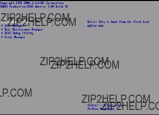
System options menu
During the boot process, the system will display the boot progress on the monitor. The SCSI BIOS scan is displayed followed by the BIOS splash screen. Press any key on the keyboard to access the System options menu.
The System options menu, the BIOS version, copyright information and the following options are displayed:
???Continue Booting
???Boot Manager
???Boot Maintenance Manager
???BIOS Setup Utility
???Error Manager
Note the following reminders when moving around the System options screen:
???Use the Up and Down arrow keys to highlight an option.
???Use the Enter key to select an option.
???Press F9 to load the default configuration.
???Press Esc to close the System Options menu.
91
Using the System options menu
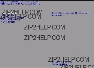
Continue Booting
Select Continue Booting option to boot from the device specified as first boot option by the Boot Manager. The Continue Booting option is selected by default, and will occur automatically if a preset timeout expires.
Boot Manager
The Boot Manager option lets you set the device priority during system bootup. The server will attempt to boot from the first device on the list. If the first device is not available, it will continue down the list until it reaches an available device..
93
Boot Maintenance Manager
The Boot Maintenance Manager option includes a menu of choices that lets you configure the boot options and boot environment variables.
The Boot Maintenance Manager include the following options:
???Boot Options - Select this option to modify the system boot order and add or delete boot options.
???Driver Options - Select this option to modify the boot driver options.
???Set Time Out Value - Select this option to modify the automatic boot time-out value.
???Reset System - Select this option to reboot the server.
BIOS Setup Utility
Select BIOS Setup Utility option to configure the server BIOS settings.
Refer to ???Using the BIOS menus??? on page 98 for more information.
95
Error Manager
Error Manager lets you view POST errors detected by the system.
BIOS setup
The BIOS setup utility stores basic settings for your server. You will need to run this utility under the following conditions:
???When changing the system configuration
???When a configuration error is detected by the system and you are prompted ("Run Setup" message) to make changes to the BIOS setup
Note: If you repeatedly receive Run Setup messages, the battery may be bad. In this case, the system cannot retain configuration values in CMOS. Ask a qualified technician for assistance.
???When redefining the communication ports to prevent any conflicts
???When changing the password or making other changes to the security settings
Entering BIOS setup
Power on the server to start the system POST process. During bootup, press F2 to enter the BIOS setup screen.
Note: You must press F2 while the system is booting. This key does not work during any other time.
There are several tabs on the setup screen corresponding to the six primary BIOS menus:
???Main
???Processor
???Memory
???Devices
???Server Management
???Security
???Save, Restore & Exit
The parameters on the screens shown in this User???s Guide display default system values. These values may not be the same as those in the system.
97
Note the following reminders when moving around the setup screen:
???Use the Left and Right arrow keys to move to the next page or to return to the previous screen.
???Use the Up and Down arrow keys to select an item.
???Use the + and - keys to select an option.
You can configure a parameter that is enclosed in square brackets. Grayed-out items have fixed settings and are not user-configurable.
???Use the Enter key to display a submenu screen.
Note: When a parameter is preceeded by a [>], it means that a submenu screen is available.
???Press F1 for General Help on using the BIOS setup.
???Press F9 to load the default configuration.
???Press F10 to save changes and close the BIOS setup.
???Press Esc to close the BIOS setup.
In the descriptive table following each of the screen illustrations, settings in boldface are the default and suggested parameter settings.
Using the BIOS menus
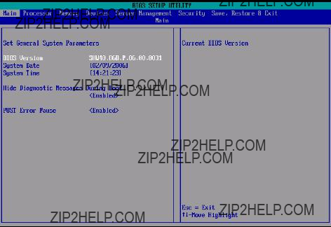
Main
The Main menu displays basic and important information about the system. These information are necessary for troubleshooting and may be required when asking for technical support. These entries are for your reference only and are not user-configurable.
The System Date and System Time parameters lets you define the sytem???s time and date settings. The real-time clock keeps the system date and time. After setting the date and time, you do not need to enter them every time you turn on the system. As long as the internal battery remains good and connected, the clock continues to keep the date and time accurately even when the power is off.
Processor
The Processor menu displays CPU settings such as type, actual speed, cache size and other CPU related settings.
Enhanced Intel
SpeedStep
Technology
When set to Auto, this feature allows the OS to reduce power consumption.
When set to Disabled, the system operates at maximum CPU speed.
Processor Information
The screen below appears when you select the Processor #1, 2, 3, or 4 Information menu. The Processor # Information submenu displays the CPU settings such as type, cache size, and other CPU related settings.
103
Memory
The Memory menu displays the total amount of memory installed, number of memory boards installed, and the current memory configuration.
Configure Memory RAS and Performance
The screen below appears when you select the Configure Memory RAS and Performance menu. This submenu allows you to view memory configuration details and configure the memory boards in the server.
15
1, 2, 3, 4, 5, 6, 7, 8, 9, 10, 11, 12, 13, 14
Disabled
512MB
1024MB
1536MB
2048MB
2560MB
3072MB
3584MB
4096MB
View Configuration Details
The screen below appears when you select the View Configuration Details menu. This submenu allows you to view detailed information regarding the current memory configuration.
Indicates the maximum possible size of memory.
Maximum effective memory size results when no spares are configured. The actual effective size will be calculated on the next system boot.
Indicates the minimum possible size of memory.
Minimum effective memory size results when the largest DIMMs are used as spare. The actual effective size will be calculated on the next system boot.
View and Configure Memory Board #
The screen below appears when you select the View and Configure Memory Board # menu. This submenu allows you to view memory board status and configure the memory boards in the server.
Healthy,
Not Installed,
Failed, or
Disabled
Devices
The Devices menu allows you to examine and set system parameters for built-in devices.
Press Enter to enter the submenu screen of the parameters shown in the screen below.
IDE Controller
The IDE Controller submenu lets you examine and set IDE controller- related parameters.
111
Mass Storage
The Mass Storage submenu displays the status of the mass storage controller
LAN
The LAN submenu displays the status of the local area network and lets you set the local area network parameters.
Indicates the media access control of the system???s LAN controller.
113
Video
The Video submenu allows you to enable or disable the onboard video controller.
USB
The USB submenu allows you to enable or disable the onboard USB controller.
115
Serial
The Serial submenu lets you define the parameter settings for the system???s serial port.
PCI
The PCI submenu lets you enable or disable the ROM scan of a device installed in the selected PCI slot. It also enables or disables posting of a 16-bit legacy ROM from the plug-in fiber channel card.
117
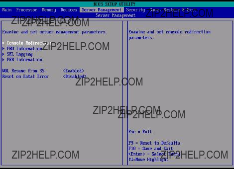
Server Management
The Server Management Configuration submenu lets you specify the appropriate settings for the system???s event handling function.
The system event log enables you to record and monitor events that occur in the system (eg., system temperature changes, fan stops, over- temperature, over-voltage, fan failures, etc.).
Console Redirection
The Console Redirection submenu lets you examine and set the COM1 console redirection parameters for server management tasks over the serial port.
Press Enter to access the COM1 Console Redirection submenu.
119
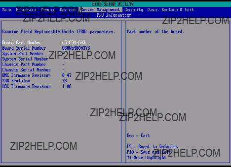
FRU Information
The FRU Information submenu lets you view the field replaceable unit parameters.
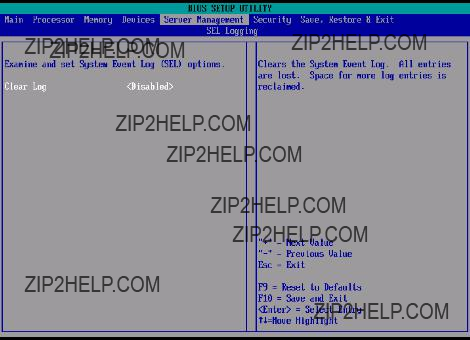
SEL Logging
The SEL Logging submenu lets you examine and set the system event log options. To clear the system event log, enable the Clear Log option. The option executes as soon as Save, Restore & Exit is peformed, then resets to Disabled.
121
FRB Information
The FRB Information submenu lets you examine and set the fault resilient boot options.
Security
The Security menu allows you to safeguard and protect the system from unauthorized use by setting up access passwords.
123
To set a Administrator/User password
1Use the up/down keys to highlight a password parameter (Set Administrator Password or Set User Password) then press Enter.
A password box will appear.
2Type a password then press Enter.
The password may consist of up to seven alphanumeric characters (A-Z, a-z, 0-9).
3Retype the password to verify the first entry then press Enter again.
After setting the password, the system automatically sets the chosen password parameter to Installed.
To change the Administrator/User password
1Use the up/down keys to highlight either change password parameters (Change Administrator Password or Change User Password) then press Enter.
2Type the original password then press Enter.
3Type a new password then press Enter.
4Retype the password to verify the first entry then press Enter again.
To remove the User password
1Use the up/down keys to highlight the Clear User Password parameter then press Enter.
2Enter the current password then press Enter.
3Press Enter twice without entering anything in the new and confirm password fields.
After doing this, the system automatically sets the User password parameter to Not Installed.
Save, Restore & Exit
The Save, Restore & Exit menu displays the various options to quit from the BIOS setup. Highlight any of the exit options then press Enter.
125
Upgrading the BIOS
The upgrade utility allows you to upgrade the BIOS in the flash memory. To prepare to upgrade the BIOS, you need to record the current BIOS settings and download the BIOS image file to a temporary folder on your hard drive or a USB flash memory device.
Recording the current BIOS settings
1Run BIOS setup. See ???Entering BIOS setup??? on page 96.
2Write down the current settings in the BIOS setup utility.
Downloading the BIOS image file
Download the image file to a temporary folder on your hard drive or a USB flash memory device.
Note: Review the instructions and release notes that are provided in the Readme file distributed with the BIOS image file before attempting a BIOS upgrade. The release notes contain critical information regarding jumper settings, specific fixes, or other information to complete the upgrade.
To upgrade the BIOS:
Follow the instructions in the Readme file that came with the BIOS upgrade. When the update completes, remove the bootable media from which you performed the upgrade.
Note: Do not power down the system during the BIOS update process. The system will reset automatically when the BIOS update process is completed. You may encounter a CMOS checksum error or other problem after reboot. It this happens, shut down the system and boot it again. CMOS checksum errors require that you enter Setup, check your settings, save your settings, and exit Setup.
This chapter provides possible solutions for specific problems. If you cannot correct the problem, contact your local Acer representative or authorized dealer for assistance.
129
Troubleshooting
This chapter helps you identify and solve problems that might occur while you are using the system.
For any issue, first ensure that you are using the latest firmware and files. In addition to the server firmware and files, make sure to update any drivers used for components you have installed in your system, such as video drivers, network drivers and SCSI drivers.
If you are unable to resolve your server problems on your own, contact your dealer or local Acer representative for assistance.
Resetting the system
Before going through in-depth troubleshooting, attempt first to perform reset the system using one of the methods below.
Problems following initial system installation
Problems that occur at initial system startup are usually caused by an incorrect installation or configuration. Hardware failure is a less frequent cause. If the problem you are experiencing is with a specific software application, see "There is problem with the application software" on page 137.
First steps checklist
???DC power available at the wall outlet?
???Are the power supplies plugged in? Check the DC cable(s) on the back of the chassis and at the DC source.
???Are all cables correctly connected and secured?
???Is the processor fully seated in the socket on the mainboard?
???Are all standoffs in the proper location and not touching any components, causing a potential short?
???Are all expansion boards fully seated in their slots on the mainboard?
???Are all jumper settings on the mainboard correct?
???Are all jumper and switch settings on expansion boards and peripheral devices correct? If applicable, ensure that there are no conflicts - for example, two expansion boards sharing the same interrupt.
???Are all peripheral devices installed correctly?
???If the system has a hard disk drive, is it properly formatted or configured?
???Are all device drivers properly installed?
???Are the configuration settings made in BIOS setup correct?
???Is the operating system properly loaded? Refer to the operating system documentation.
???Did you press the system power button on the front panel to turn the server on (power indicator should be lit)?
???Is the system power cord properly connected to the system and plugged into an outlet for 200-240 V?
???Are all integrated components from the tested components lists? Check the tested memory, and chassis lists, as well as the supported hardware and operating system list.
131
Hardware diagnostic testing
This section provides a more detailed approach to identifying a hardware problem and locating its source.
Caution! Before disconnecting any peripheral cables from the system, turn off the system and any external peripheral devices. Failure to do so can cause permanent damage to the system and/ or the peripheral devices.
1Turn off the system and all external peripheral devices. Disconnect each of device from the system, except for the keyboard and the video monitor.
2Make sure the system power cord is plugged into a properly grounded DC outlet.
3Make sure your video display monitor and keyboard are correctly connected to the system. Turn on the video monitor. Set its brightness and contrast controls to at least two thirds of their maximum ranges (see the documentation supplied with your video display monitor).
4If the operating system normally loads from the hard disk drive, make sure there is no disc in the optical drive.
5If the power indicator does light, attempt to boot from a disc.
6Turn on the system. If the power indicator does not light, see ???Power indicator does not light??? on page 132.
Verifying proper operation of key system lights
As POST determines the system configuration, it tests for the presence of each mass storage device installed in the system. As each device is checked, its activity light should turn on briefly. Check if the HDD activity indicator lights briefly? If not, see ???HDD activity indicator does not light.??? on page 133.
Confirming loading of the OS
Once the system boots up, the operating system prompt appears on the screen. The prompt varies according to the operating system. If the operating system prompt does not appear, see "No Characters Appear on Screen" on page 137.
Specific problems and corrective actions
The following contains specific problems that may arise during the use of your server. Possible solutions are listed for each problem.
Power indicator does not light.
Do the following:
???Make sure the power button on the front panel is turned on.
???Make sure the power cable is connected correctly.
???Make sure that the wall outlet has power. Test it by plugging another device.
???Remove all non-hot-plug expansion cards and see if the system boots. If successful, add the cards back in one at a time with a reboot between each addition.
???Make sure the memory board and memory modules comply with the system requirements.
???Make sure the memory modules have been populated according to the system requirements.
???Remove and reseat the memory board.
???Remove and reseat the memory modules.
???Make sure the CPU complies with the system requirements.
???Make sure the CPU is populated according to the system requirements.
???Remove and reseat the CPU.
???Make sure the chassis standoffs are installed only below mounting holes. Misplaced standoffs may have contact to the pins on the bottom of the mainboard and cause a short.
???Make sure the VRMs are plugged in and the pins are not bent.
Server powers on but turns off often with fault light
Do the following:
???Make sure the VRMs are plugged in and the pins are not bent.
???Make sure the memory boards are properly seated.
???Make sure the CPU is properly seated.
133
Server boot does not complete POST
Do the following:
???Make sure the VRMs are plugged in and the pins are not bent.
???Make sure the CPU is properly seated.
???Check the BIOS release notes to ensure the BIOS installed on the platform supports the stepping and the family of processors currently installed.
???Make sure the memory boards are populated according to system requirements.
Server does not recognize all of the processors installed
Do the following:
???Make sure the VRMs are plugged in and the pins are not bent.
???Make sure the CPU is properly seated.
HDD activity indicator does not light.
Do the following:
???Make sure the drive is not disabled in the BIOS setup utility.
???Make sure the drive???s power and data cables are connected correctly.
???Make sure the drive is compatible.
???Make sure you have not exceeded the power budget for the server.
???If using SCSI drives, make sure that each SCSI ID number is unique on the SCSI bus. See your drive documentation for details on setting the SCSI ID for your drives.
???If using a RAID configuration with SCSI drives, make sure the RAID card is installed correctly.
If you have installed one or more hard drives in the system, do the following:
???Make sure the power and signal cables are connected correctly.
???If using SCSI drives, check that relevant switches and jumpers on the hard drive and backplane board are set correctly.
ODD (Optical disk drive) activity indicator does not light.
Do the following:
???Make sure the power and signal cables are properly installed.
???Check that relevant switches and jumpers on the drive are set correctly.
???Check that drive is properly configured.
???Check that onboard IDE controller is enabled in the BIOS setup.
ODD tray cannot be ejected.
???Insert the tip of a paperclip into the small hole on the ODD drive. Slowly pull the tray out from the drive until the tray is fully extended then remove the disc.
ODD drive cannot read a disc.
Do the following:
???Make sure you are using the correct type of disc.
???Make sure the disc is properly seated in the drive.
???Make sure the disc is unscratched.
???Make sure all cables are connected to the ODD.
Hard drives are not recognized.
???Make sure the drive is not disabled in the BIOS setup.
???Make sure the drive is connected correctly and the power cable is plugged to the power supply.
???Make sure the drive is compatible.
???Make sure that you have not exceeded the power budget for the server.
135
???If using SCSI drives, verify that each SCSI ID numbers is unique on the SCSI bus. Refer to the drive documentation for details on setting the SCSI ID for your drives.
???If using IDE drives, verify that the master/slave settings are set correctly. Refer to the drive documentation for details on setting the master/slave settings.
???If using RAID configuration with SSCSI drives, make sure the RAID card is installed correctly.
Bootable CD drive is not detected.
Make sure the Boot settings in the BIOS setup utility is configured to allow the CD drive to be the first bootable device.
New memory modules installed are not detected.
Do the following:
???Make sure the memory modules are properly seated on the memory board???s DIMM slots.
???Make sure the memory modules comply with the system requirements.
???Make sure the memory modules have been populated according to the system requirements.
External device connected to a USB connector does not work.
Do the following:
???Reduce the number of external devices connected to a USB hub.
???Refer to the documentation that came with the device.
Cannot connect to a server
???Make sure the network cable is securely attached to the correct connector at the system rear panel.
???Try a different network cable.
???Make sure you are using the correct and the current drivers.
???Make sure the driver is loaded and the protocls are bound.
No video but LED on the front panel indicates system is in reset mode
???Make sure the VRMs are plugged in and the pins are not bent.
???Replace the failed VRM.
Problems with the network
Network status indicator does not light.
Do the following:
???Check the cabling and network equipment to make sure that all cables are properly connected.
???Reinstall the network drivers.
???Try another port or hub on the switch.
Diagnostics pass but the connection fails.
???Make sure the network cable is securely attached.
???Make sure you specify the correct frame type in the NET.CFG file.
The controller stopped working when an adapter was installed.
???Make sure the cable is connected to the port from the onboard network controller.
???Make sure the other adapter supports shared interrupts and your OS supports shared interrupts.
???Try reseating the adapter.
The adapter stopped working without apparent cause.
???Try reseating the adapter first, then try a different slot if necessary.
137
???The network files driver may be corrupt or deleted. Delete and reinstall the drivers.
???Run the diagnostics.
Network activity indicator does not light.
Do the following:
???Make sure the correct network drivers are loaded on the system.
???Network might be idle. Try accessing the server.
Server hangs when the drivers are loaded.
Change the PCI interrrupt settings.
There is problem with the application software.
Do the following:
???Verify that the software is properly configured for the system. Refer to the software installation and operation documentation for instructions on setting up and using the software.
???Try a different version of the software to see if the problem is with the copy you are using.
???Make sure all cables are properly connected.
???If other software runs correctly on the system, contact your vendor about the defective software.
No characters appear on the screen.
Check the following:
???Is the keyboard functioning? Test it by turning the ???Num Lock??? function on and off to make sure the Num Lock light is functioning.
???Is the video monitor plugged in and turned on? If you are using a switch box, is it switched to the correct system?
???Are the brightness and contrast controls on the video monitor properly adjusted?
???Is the video monitor signal cable properly installed?
???Does this video monitor work correctly if plugged into a different system?
???Is the onboard video controller enabled in the BIOS setup?
???Remove all expansion cards and see if the system boots. If successful, add the cards back in one at a time with a reboot between each addition.
???Make sure the memory modules comply with the system requirements.
???Make sure the memory modules have been populated according to the system requirements.
???Remove and reseat the memory boards.
???Remove and reseat the memory modules.
???Make sure the CPU complies with the system requirements.
???Make sure the CPU is populated according to the system requirements.
If you are using a video controller board, do the following:
1Verify that the video works using the onboard video controller.
2Verify that the video controller board is fully seated in the mainboard connector.
3Reboot the system for changes to take effect.
4If there are still no characters on the screen after you reboot the system and POST emits a beep code, write down the beep code you hear. This information is useful for your service representative.
5If you do not receive a beep code and characters do not appear, the video display monitor or video controller may have failed. Contact your service representative or authorized dealer for help.
Characters are distorted or incorrect.
Check the following:
???Are the brightness and contrast controls properly adjusted on the video monitor? Refer to the documentation that came with the video monitor.
139
???Are the video monitor???s signal and power cables properly connected.
???Is the video monitor working correctly when plugged into a different system?
System cooling fan do not rotate properly.
If the system cooling fan is not operating properly, it is an indication of possible system component failure.
Check the following:
???Is the power indicator lit? If not, see ???Power indicator does not light.??? on page 132 .
???Are any other front panel LEDs lit?
???Have any of the fan motors stopped? Use the server management subsystem to check the fan status.
???Have your fans speeded up in response to an overheating situation?
???Have your fans speeded up in response to a fan that has failed?
???Is the fan???s power connector properly connected to the mainboard?
???Is the front panel board cable connected to both the mainboard???s front panel board connector?
???Are the power supply cables properly connected to the mainboard?
???Are there any shorted wires caused by pinched cables or have power connector plugs been forced into power connector sockets the wrong way?
Appendix A: Acer Altos R910
This appendix shows you how to set up the Altos R910 server in a rack mount configuration.
143
Setting up the system rack
Important! Observe the electrostatic discharge (ESD) precautions indicated on page 33 when perfoming the following procedures. Do not attempt the procedures described in the following sections unless you are a qualified technician.
Equipment rack precautions
Follow the rack manufacturer's safety and installation instructions for proper rack installation.
The following additional rack safety installation measures should be considered:
???Anchor the equipment rack
The equipment rack must be anchored to an unmovable suitable support to prevent the rack from falling over when one or more systems are fully extended out of the rack assembly. You must also consider the weight of any other devices installed in the rack assembly. The equipment rack must be installed according to the manufacturer's instructions.
???Main DC power disconnect
You are responsible for installing an DC power disconnect for the entire rack unit. This main disconnect must be readily accessible, and it must be labeled as controlling power to the entire unit, not just to the system(s).
???Earth ground the rack installation
To avoid the potential for an electrical shock hazard, the rack assembly itself must be suitably earth grounded, according to your local regional electrical codes. This typically will require the rack to have its own separate earth ground. We recommend you consult your local approved electrician.
???Elevated operating ambient temperature
The maximum operating temperature of the system is 35 ??C (95??F). Careful consideration should be given to installing the system in an environment compatible with the 35 ??C (95??F) maximum ambient temperature.
???Reduced airflow
The amount of airflow required for the safe operation of the equipment should not be compromised when installing the system in a rack.
???Mechanical loading
Exercise care when mounting the system in a rack to avoid any accidents.
???Circuit overloading
Appropriate consideration should be given when connecting the supply circuit to the system to avoid any circuit overload. The system name plate rating should be used when addressing concerns about circuit overload.
145
System rack installation
The Altos R910 server system should be mounted into a rack cabinet. A rack rail and CMA (cable management arm) kit is available for installing system to a rack cabinet.
The figure below shows the Altos R910 server in a rack-mount position.
Vertical mounting hole pattern
The four vertical rails of the system rack contain mounting holes arranged in a manner shown in the figure below:
The system occupies 4U in the rack. Count the U positions and hole numbers from the bottom up.
The distance from the center of two holes with closer spacing to the center of the next pair is equivalent to 1U.
Note: The unit of measurement used in this guide is "U"
(1U = 1.75 inches or 44.45 mm). The total sum of the heights of all components in the rack measured in "U" cannot exceed the height of the rack. For more information, refer to the documentation that came with the system rack.
When installing components, you must start your measurement from the center of the two holes with closer spacing. Otherwise, the screw holes on the component may not match those on the rack.
147
Installing the system into the rack
Caution! To minimize the chances of injuries, make sure that two or more people help in installing the server.
To install the system into a four-post rack
1Remove the inner rails from the mounting rails.
(1)Extend the inner rail from the mounting rail until the rail release latch clicks.
(2)Depress the release latch (A) and slip the inner rail out (B).
(3) Do the same thing to the other mounting rail.
Caution! To avoid personal injury, care should be taken when pressing the inner rail release latches and sliding the component into the rack.
2Attach the inner rails to both sides of the server.
Please use screws that came with the rack-mount kit when attaching the inner rails to both sides of the server. If your system already has screws attached, please remove them.
Note: Using screws other than those supplied in this rack-mount kit to attach the rails will void the warranty, Acer cannot be held responsible for any damage for incorrect installation.
(1)Align the screw holes of the inner rail to the server screws (A).
(2)Slide the rails to the left until the rails lock into place with an audible click (B).
149
3Install the mounting rails to the rack posts.
(1)Determine the vertical position in the rack. Refer to ???Vertical mounting hole pattern??? on page 146 for more information.
(2)Align and insert the mounting rail into the rack posts??? mounting holes (A).
(3)Make certain the proper mounting holes on the rack post are selected.
(4)Use two metal screws to secure the front and rear mounting rail to the rack (B).
(5)Do the same thing to the other mounting rail.
(6) Fully extend the mounting rails on the rack.
151
4 Install the server into the rack.
Caution! To avoid personal injury, care should be taken when pressing the inner rail release latches and sliding the component into the rack.
(1)Carefully align the inner rails attached to the server with the fully extended mounting rails on the rack.
(2)Press the release latch on both sides of the server (A).
(3)Insert the inner rails into the mounting rails, then push the server into the rack until you hear a click sound (B).
(4)Secure the server to the rack using the two front panel thumbscrews (C).
5Attach the CMA (cable management arm) to the rear of the server.
The CMA allows you to tie-wrap all cables to and from the system. As you slide the system in and out of the rack, the CMA collapses and extends, keeping the cables untangled and attached to the system.
(1)Insert the smaller CMA extension into the rear of the left inner rail (A1).
(2)Insert the larger CMA extension into the rear of left mounting rail (A2).
(3)Insert the CMA extension connector into the rear of the right mounting rail (B1).
(4)Insert the CMA arm connector into the blue plastic cutout on the CMA extension connector (B2).
(5)Attach the cable clips into the appropriate mounting holes in the CMA (C).
153
(6)Connect the power, peripheral and networking cables into their appropriate ports.
Refer to ???Connecting peripherals??? on page 26 for detailed instructions.
(7)Route all cables through the cable clips.
Appendix B: Memory
configuration options
This chapter provides details on how to configure the system memory boards in either a redundant or non-redundant configuration. Recommended memory board and DIMM installation order and DDR2 DIMM population order tables are also included.
157
Introduction
The system supports installation of up to four memory boards to the mainboard. Memory boards connect to the mainboard through the x16 PCI Express slots or memory board slots A, B, C, and D (refer to ???Mainboard??? on page 17 for the location of the memoy board slot). The memory board is equipped with four DIMM slots that support two DDR2 channels, with two DIMMs installed per channel (DIMM 1A or 1B or DIMM 2A or 2B). Each DIMM slot supports 512 MB, 1 GB, 2 GB or 4 GB DDR2-400 MHz (PC2-3200) registered ECC memory modules.
Important: DDR2 DIMM modules on each memory board must be installed in pairs. Each pair is referred to as a bank. A bank may consist of one rank (a pair of single-channel DIMMs) or two ranks ( a pair of dual-channel DIMMs).
When using dual-channel memory mode, use the same type and size DDR2 DIMM modules and follow the ???DIMM module population order??? on page 159 to ensure that you get dual- channel memory performance.
The memory boards can be configured in a redundant or non- redundant configuration. Memory boards configured using RAID or mirroring are in redundant configuration. If a memory board that is configured in a redundant configuration has a DIMM or memory board fault, the memory board and/or DIMM containing the fault can be removed and replaced while the system is powered on (See page 51 for detailed instructions on how to hot-remove and hot-replace memory boards). Memory boards that are configured in a non-redundant configuration (including memory boards configured with spare memory) must not be removed while the system is powered on (Refer to page 69 for detailed instructions on how to remove and replace memory boards.).
Installation and population order
Memory board installation order
The table below lists the suggested memory board installation order.
of two or four sets of memory boards, paired as sets of two. Each memory board in a set must have same amount of memory board installed.
Note: Requires installation of four memory boards with equal memory capacity.
DIMM module installation order
The table below lists the suggested DIMM module installation for a memory board:
159
DIMM module population order
The tables below list the suggested DDR2 DIMM module population for normal configuration.
Population with one memory board
Population with two memory boards
Population with four memory boards
DIMM population with sparing
The tables below list the suggested DDR2 DIMM module population for memory sparing configuration.
Population with one memory board
* Only 4GB of memory installed in DIMM 1A/1B slots will be reserved as spare DIMMs, one rank from each dual-rank DIMM.
Population with two memory boards
* Only 4GB of memory installed in DIMM 1A/1B slots will be reserved as spare DIMMs, one rank from each dual-rank DIMM.
* Only 4GB of memory installed in DIMM 1A/1B slots will be reserved as spare DIMMs, one rank from each dual-rank DIMM.
DIMM population with mirroring
The tables below list the suggested DDR2 DIMM module population for memory mirroring configuration.
Population with two memory boards
162Appendix B: Memory configuration options
Population with four memory boards
DIMM population with RAID
Population with four memory boards
163
Memory modes
The server supports several memory features that allow flexibility in performance, redundancy, and ability to upgrade. The system BIOS can be configured as follows:
???Maximum compatibility
???Maximum performance
???Memory sparing
???Memory RAID
???Memory mirroring
Only one of these memory modes can be selected at one time and the BIOS defaults to maximum performance mode. For non-redundant modes, support is also included for memory sparing, where a portion of each memory board is reserved for failover.
The table below lists the memory hot-plug support under different memory modes.
Memory boards configured using RAID or mirroring are in redundant mode. If a memory board that is configured in a redundant mode has a DIMM or memory board fault, the memory board and/or DIMM containing the fault can be hot-removed or hot-replaced while the system is powered on.
Hot-replace means you can replace a memory board with another memory board of identical size. This operation is supported in memory RAID and memory mirroring modes.
Hot-add means you can add a memory board to a previously unoccuppied slot. This requires OS support and is supported in maximum compatibility and memory mirroring modes.
Hot-upgrade means you can replace an existing memory board with a memory board that contains more memory capacity. This requires OS support and is supported by the memory RAID mode only.
Maximum compatibility
Maximum compatibility provides the most flexibility with DIMMs and memory boards. With this configuration mode, you can hot-add memory boards and allocate ranks to serve as spare on each memory board. This memory mode is one-way interleaved and has the lowest performance among the supported configurations.
To configure memory to maximum compatibility:
1Do any of the following:
??? Run BIOS setup. See ???Entering BIOS setup??? on page 96.
- or -
aDuring system bootup, enter the System Options Menu. See ???System options menu??? on page 90.
bUse the up and down arrow keys to select BIOS Setup Utility, then press Enter. The BIOS main menu displays on the monitor.
2Use the up and down arrow keys to select the Memory menu, then press Enter. The Memory menu appears.
3Use the up and down arrow keys to select Configure Memory RAS and Performance, then press Enter. The Configure Memory RAS and Performance menu appears.
4Set the Desired Memory Configuration to either Maximum Compatibility.
165
5Select View Configuration Details.
Make sure Configuration Possible indicates Yes. If the option indicates No, you may need to install more memory to meet the requirements of the selected configuration.
6Press F10 to save changes and exit.
7Press Y to confirm. The server reboots to activate the changes.
Maximum performance
Maximum performance is the default memory configuration and provides the best performance. With four memory boards installed, the BIOS configures memory as four-way interleaved, across all memory boards. With less than four memory boards installed, the BIOS attempts to configure two-way interleaving. If memory cannot be configured for two-way interleaving, the BIOS defaults to one-way interleaving. This memory mode allows sparing configuration but does not support any memory board hot-plug operations.
To configure memory to maximum performance:
1Do either option below:
??? Run BIOS setup. See ???Entering BIOS setup??? on page 96.
- or -
aDuring system bootup, enter the System Options Menu. See ???System options menu??? on page 90.
bUse the up and down arrow keys to select BIOS Setup Utility, then press Enter. The BIOS main menu displays on the monitor.
2Use the up and down arrow keys to select the Memory menu, then press Enter. The Memory menu appears.
3Use the up and down arrow keys to select Configure Memory RAS and Performance, then press Enter. The Configure Memory RAS and Performance menu appears.
167
4Set the Desired Memory Configuration to either Max Performance.
5Select View Configuration Details.
???Make sure Configuration Possible indicates Yes. If the option indicates No, you may need to install more memory to meet the requirements of the selected configuration.
6Press F10 to save changes and exit.
7Press Y to confirm. The server reboots to activate the changes.
Memory sparing
Sparing allows for memory to be set aside to replace memory under use when a DIMM???s correctable error count has reached a specified threshold. Spared memory configurations do not provide redundant copies of memory and the system cannot continue to operate when an uncorrectable error occurs.
The DIMMs on each memory board must be installed in pairs. Each pair is referred to as a bank. A bank may consist of one rank (a pair of single-sided DIMMs) or two ranks (a pair of double-sided DIMMs). You can refer to ???Installing DIMMs??? on page 73 for instructions on how to install a DIMM on a memory board.
When the memory mode is set to maximum performance or maximum compatibility, the BIOS setup supports setting one rank aside to server as spare for each memory board. When the correctable error rate for a failing rank exceeds the error threshold for switching to spare, the contents of the failing rank are copied to the spare rank. At the completion of the copy, the failing rank is disabled and the spare rank is used in its place. The BIOS reports the failing rank with a SEL (system event log) event, updates the DIMM error LED on the memory board, and sends memory RAS (reliability, availability, and serviceability) commands to the BMC (baseboard management controller) to update the system memory state. The DIMMs with the failed rank are disabled on subsequent boots. The spare rank is no longer used for spare, but instead used as a system memory.
When the BIOS setup is configured for sparing, the largest rank is chosen to serve as the spare. This ensures that the contents of any failing rank fit on the spare rank. The amount of the available memory in the system is reduced by the size of the spare rank. If only one rank is available on a memory board, the system BIOS does not configure this rank as a spare.
The BIOS setup utility executes a memory test prior to configuring the memory in POST and when a memory board is inserted into the system during a memory hot-removal or hot-add operation.
To configure memory sparing:
1Do either option below:
??? Run BIOS setup. See ???Entering BIOS setup??? on page 96. - or -
169
aDuring system bootup, enter the System Options Menu. See ???System options menu??? on page 90.
bUse the up and down arrow keys to select BIOS Setup Utility, then press Enter. The BIOS main menu displays on the monitor.
2Use the up and down arrow keys to select the Memory menu, then press Enter. The Memory menu appears.
3Use the up and down arrow keys to select Configure Memory RAS and Performance, then press Enter. The Configure Memory RAS and Performance menu appears.
4Set the Desired Memory Configuration to either Max Performance or Maximum Compatibility.
5Select View Configuration Details.
???Make sure Configuration Possible indicates Yes. If the option indicates No, you may need to install more memory to meet the requirements of the selected configuration.
???Make sure that Sparing indicates Yes.
6Return to the Memory menu option and set the Sparing Threshold value from 1 through 15.
7Select View and Configure Memory Board X option (where X is the memory board that is being configured).
Make sure that Board Status indicates Healthy.
8Set the Reserve Rank for Spare to Enabled.
9Press F10 to save changes and exit.
10Press Y to confirm. The server reboots to activate the changes.

Memory RAID
If four memory boards with equal memory capacity are installed on the server, the system can be configured for Memory RAID. Memory RAID mode acts similar to RAID level 4, where data is written to three of the memory boards and the fourth is held in reserve for memory parity information.
When one board fails, the memory subsystem operates in non- redundant mode. The data from the remaining three boards is used to reconstruct the data that was on the failed memory board. When the failed memory board location is hot-replace, the BIOS rebuilds the RAID by reconstructing the data that was on the previously failed memory board and writes the data to the newly installed board. When the rebuild is complete, the system is once again in redundant mode. The BIOS sets the memory board RAID LED to indicate that the memory board is operating in the memory RAID mode.
To configure memory RAID
1Do either option below:
??? Run BIOS setup. See ???Entering BIOS setup??? on page 96.
- or -
aDuring system bootup, enter the System Options Menu. See ???System options menu??? on page 90.
bUse the up and down arrow keys to select BIOS Setup Utility, then press Enter. The BIOS main menu displays on the monitor.
171
2Use the up and down arrow keys to select the Memory menu, then press Enter. The Memory menu appears.
3Use the up and down arrow keys to select Configure Memory RAS and Performance, then press Enter. The Configure Memory RAS and Performance menu appears.
4Set the Desired Memory Configuration to RAID.
5Select View Configuration Details.
Make sure Configuration Possible indicates Yes. If the option indicates No, you may need to install more memory to meet the requirements of the selected configuration.
6Press F10 to save changes and exit.
7Press Y to confirm. The server reboots to activate the changes.
Memory mirroring
Memory mirror requires either two or four same size memory boards and provides redundancy at the cost of halving the effective memory size. The memory configuration allows for the hot-replacement of an existing board for a board containing an equal amount of memory or the hot-addition of two memory boards to a pair of empty memory board slots only.
A pair of memory boards in memory mirror mode forms a redundant group. One of the memory boards is designated the primary image and the other the secondary image. For memory writes, the write request is issued to both boards. For memory reads, the read request is issued to the primary memory board. In the event of a detected uncorrectable error, the primary and secondary images switches with each other and the failed image cannot become the primary image again until the failed DIMMs have been replaced and the image re-built. The first redundant group consists of memory board A mirrored with memory board B. The second redundant group consists of memory board C mirrored with memory board D. The BIOS sets the memory board mirror LED to indicate that the memory board is operating in the memoy mirror mode.
To configure memory mirroring:
1Do either option below:
??? Run BIOS setup. See ???Entering BIOS setup??? on page 96.
- or -
aDuring system bootup, enter the System Options Menu. See ???System options menu??? on page 90.
173
bUse the up and down arrow keys to select BIOS Setup Utility, then press Enter. The BIOS main menu displays on the monitor.
2Use the up and down arrow keys to select the Memory menu, then press Enter. The Memory menu appears.
3Use the up and down arrow keys to select Configure Memory RAS and Performance, then press Enter. The Configure Memory RAS and Performance menu appears.
4Set the Desired Memory Configuration to Mirror.
5Select View Configuration Details.
Make sure Configuration Possible indicates Yes. If the option indicates No, you may need to install more memory to meet the requirements of the selected configuration.
6Press F10 to save changes and exit.
7Press Y to confirm. The server reboots to activate the changes.
Appendix C: Integrated SCSI
hardware RAID configuration
This appendix shows you how to create a RAID volume with integrated SCSI hardware RAID.
177
Configuring the integrated SCSI hardware RAID
This section briefly shows how to create RAID with integrated SCSI hardware RAID.
Starting integrated SCSI hardware RAID configuration utility
To start Integrated SCSI Hardware RAID Configuration Utility, press <CTRL-G> when you see the RAID BIOS during POST. After POST finished, the Adapter Selection page will show on the screen. Click Start to launch the configuration menu.
Loading factory default setting
1In the Configuration menu, select Adapter Properties. The current adapter settings appear.
2Change the setting of Set Factory Defaults from No to Yes, then click Submit.
3Press <Ctrl+Alt+De>l to reboot the server.
Creating and Initialing a RAID Volume
1Launch the Configuration menu.
2Select Configuration Wizard.
3Select Add Configuration (default) and click Next.
4Select Custom Configuration (default) and click Next.
5Select the drives that you want to add into the array using the <Ctrl> key.
6After you select the drives, click Accept Array then Next.
7Select the RAID Level you want to use, create the logical volume by specifying the size at Select Size and click Accept to create the logical volume.
8After you create the logical volumes on all of the RAID volume, click Accept and Yes to save the configuration.
9Click Yes to initialize the new logical drives. The logical drives will be listed.
10Click Home to go back to the configuration menu.
11Now you can reboot the system and install the Operating System. Select Exit and click Yes.
12Press <Ctrl+Alt+Del> to reboot the system.
Assigning a hot spare disk
1Launch the Configuration menu.
2Select a free disk marked as Ready and listed under Physical Drives.
3Select Make Hotspare and click Go.
4Click Home to return to the Configuration menu. The disk will be marked as Hotspare in pink and listed under Physical Drives.
Index
Numerics
5.25-inch drive installing 60
A
ARMC/3 module installing 77 removing 77
B
C
cold-plug memory board installing 71 removing 70
180
M
N
non-hot-plug PCI card installing 76 removing 76
O
removing memory board air baffle
42
removing the front bezel 35
removing the top cover 36
P
R
S
setting up the system 25
181
T
U
upgrading the BIOS 125