Veriton 5100/7100
Service Guide
Service guide files and updates are available on the AIPG/CSD web; for more information, please refer to http://csd.acer.com.tw
Veriton 5100/7100
Service Guide
Service guide files and updates are available on the AIPG/CSD web; for more information, please refer to http://csd.acer.com.tw

Copyright
Copyright ?? 1999 by Acer Incorporated. All rights reserved. No part of this publication may be reproduced, transmitted, transcribed, stored in a retrieval system, or translated into any language or computer language, in any form or by any means, electronic, mechanical, magnetic, optical, chemical, manual or otherwise, without the prior written permission of Acer Incorporated.
Disclaimer
The information in this guide is subject to change without notice.
Acer Incorporated makes no representations or warranties, either expressed or implied, with respect to the contents hereof and specifically disclaims any warranties of merchantability or fitness for any particular purpose. Any Acer Incorporated software described in this manual is sold or licensed "as is". Should the programs prove defective following their purchase, the buyer (and not Acer Incorporated, its distributor, or its dealer) assumes the entire cost of all necessary servicing, repair, and any incidental or consequential damages resulting from any defect in the software.
Acer is a registered trademark of Acer Corporation. Intel is a registered trademark of Intel Corporation.
Pentium and Pentium II/III are trademarks of Intel Corporation.
Other brand and product names are trademarks and/or registered trademarks of their respective holders.
II

Conventions
The following conventions are used in this manual:
III

Preface
Before using this information and the product it supports, please read the following general information.
1.This Service Guide provides you with all technical information relating to the BASIC CONFIGURATION decided for Acer's "global" product offering. To better fit local market requirements and enhance product competitiveness, your regional office MAY have decided to extend the functionality of a machine (e.g.
2.Please note WHEN ORDERING FRU PARTS, that you should check the most
IV

Table of Contents
Front
Rear
Front
Rear
Hardware Specifications and Configurations . . . . . . . . . . . . . . . . . . . . . . . . . . . 16
V

Chapter 1
System Specifications
Overview
The Veriton 5100/7100 supports Intel?? Pentium III Flip

Features
Performance
!Intel?? Pentium III processor which uses the
!128/256 KB PBSRAM L2 cache incorporated in Intel?? Pentium III (Coppermine) processor.
!Maximum of 512 MB SDRAM within 3 DIMM slots up to 133MHz.
!Support AGP 2.0 including 4x AGP data transfers.
!Integrated LAN Controller (82801BA).
!
!
!High capacity,
!Power management features
!CPU SMM (System Management Mode), STOP clock control
!
!PIO mode 4
!Ultra DMA/100, Ultra DMA/66 & Ultra DMA/33 modes
!
!Power management features
!Support for
!ACPI 1.0 compliant
!Software shutdown for Windows 95/98
!Hardware monitor function (only support SMB)
Multimedia
!
!
Connectivity
!One AGP and three PCI slots
!PS/2 mouse and keyboard interface
!Two serial and one parallel interface
!Four USB ports ( available on front and rear panels)
!
!

!Slim desktop form factor
!Separate computer stand and rubber stands for quick and easy positioning
!
!Accessible I/O ports
!
Front
NOTE: The system has two

Rear

NOTE: The system has two
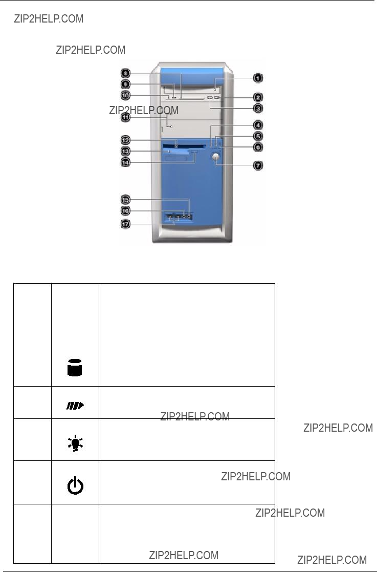
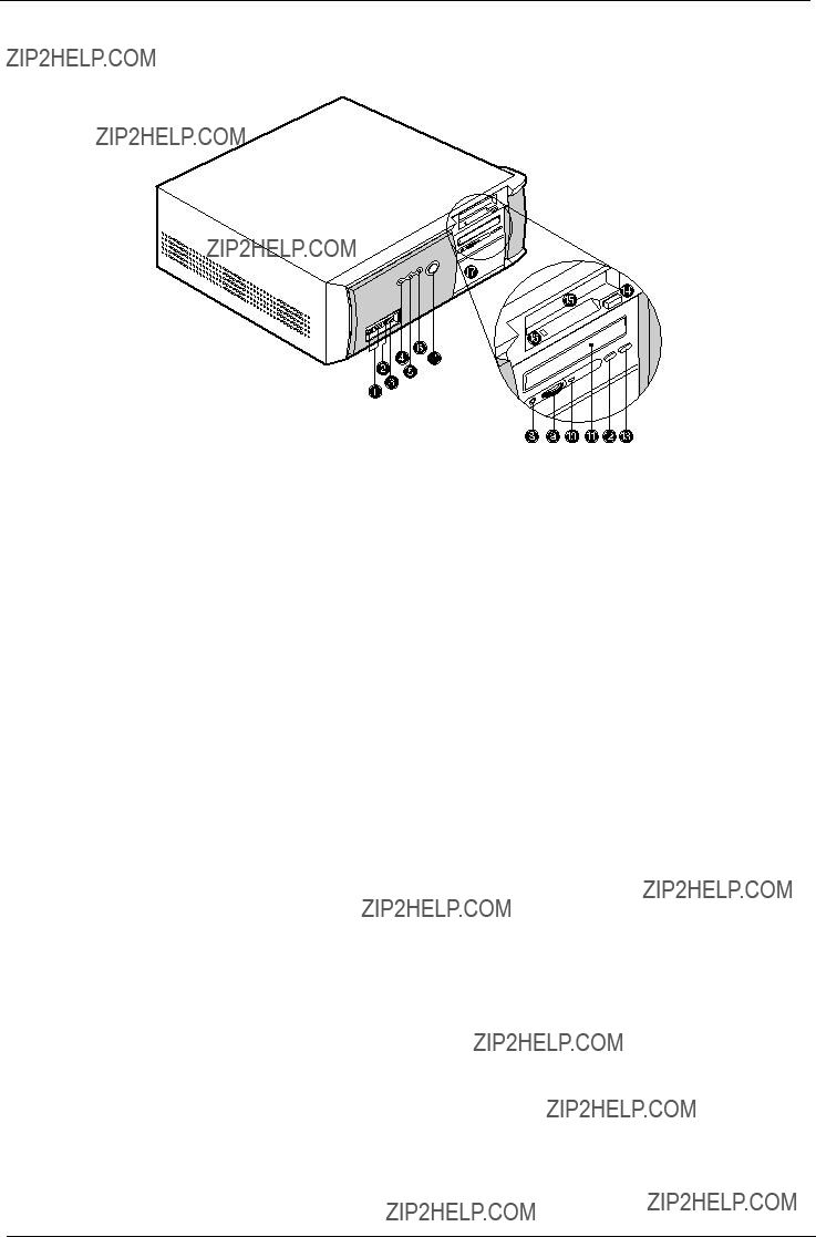
Front
The computer???s front panel consists of the following:

* The system has two

Rear
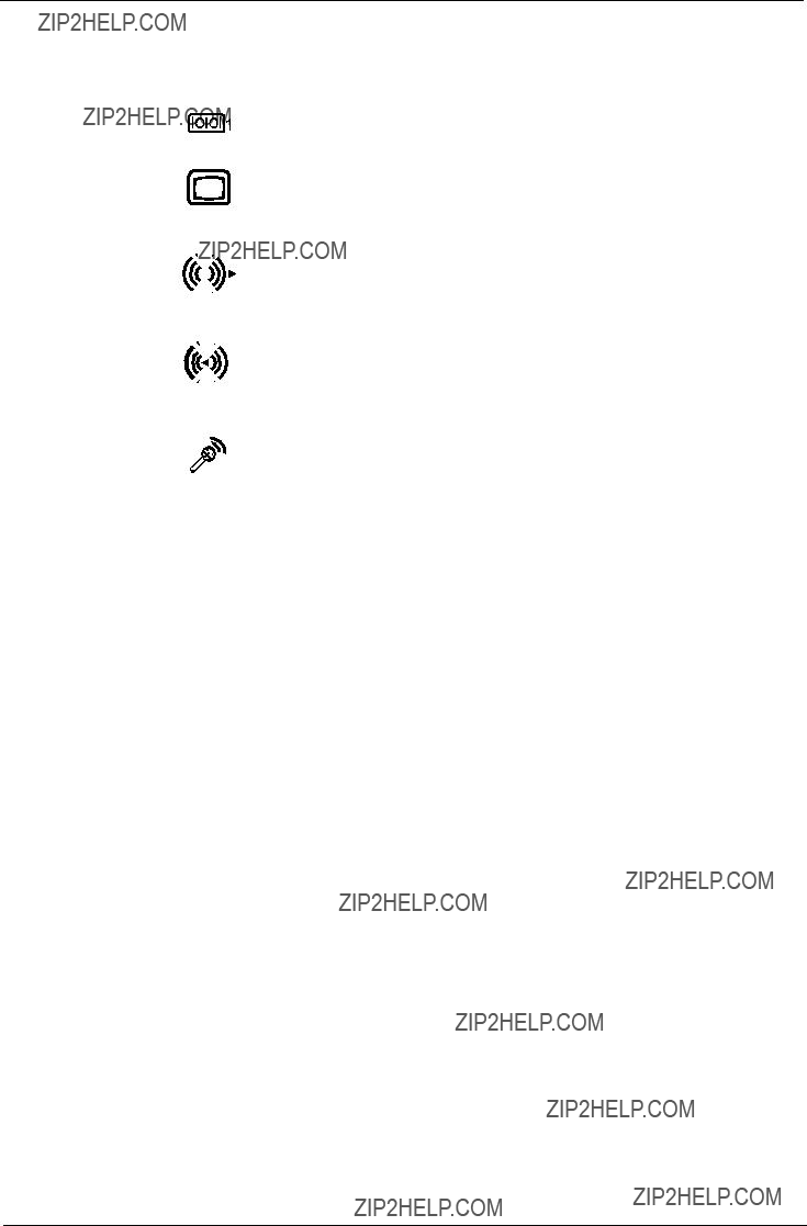
* The system has two

Main Board Layout

Keyboard
The keyboard has
Programmable keys
The programmable keys help you directly access a URL (Web site) or launch any program, files, or application in your system. The fifth key is set to launch the media player. If you want to configure the settings of each key right click on the Magic Keyboard icon located on the desktop.
Internet/Suspend keys
The internet/Suspend keys consist of three buttons:

Multimedia keys
Allow you to play, pause, stop, step forward, or step back a song or movie conveniently using your keyboard.
Volume control/Mute
The volume control/Mute knob controls the speaker volume. Turn it clockwise or counterclockwise to adjust the volume. Press it to toggle between mute and sound.
Cursor keys
The cursor keys, also called the arrow keys, let you move the cursor around the screen. They serve the same function as the arrow keys on the numeric keypad when the Num Lock is toggled off.
Lock keys
The keyboard has three lock keys which you can toggle on and off to switch between two functions.
Windows keys
The keyboard has two keys that perform

Hardware Specifications and Configurations
Processor
BIOS
NOTE: The BIOS can be overwritten/upgraded using the AFLASH utility (AFLASH.EXE).
BIOS Hotkey List

This section has two table lists, system memory specification and the possible combinations of memory module.
System Memory
Memory
Memory
NOTE: For Memory
Cache Memory
Below information is only applicable to system with installed Pentium III processor.
17

Video Interface
*32 - 24bpp color data is processed using a 32bpp data format.
NOTE: You may disable the

Audio Interface
IDE Interface
Floppy disk drive Interface

Parallel Port
Serial Port
Modem
USB Port

Memory Address Map
PCI INTx# and IDSEL Assignment Map
PCI Slot IRQ Routing Map

I/O Address Map
IRQ Assignment Map
NOTE: N - Not in use

DRQ Assignment Map

Switching Power Supply 145W
(This is for 145 power supply)
NOTE: 1. This "4A" includes the outlet supply current: 2A.
2. Measure at line input 90VRMS and maximum load condition.
NOTE: +5V and 3.3V total power is 100W max.
Power Management Functions
Device Standby Mode
!Independent power management timer for hard disk drive devices
!Hard disk drive goes into Standby mode (for ATA standard interface).
!Disable
!Resume method: device activated (Keyboard for DOS, keyboard & mouse for Windows).
!Resume recovery time:
Global Standby Mode
!Global power management timer
!Hard disk drive goes into Standby mode (for ATA standard interface).
!Disable
!Resume recovery time:
Suspend Mode
!Independent power management timer
!CPU goes into SMM.
!CPU asserts STPCLK# and goes into the Stop Grant State.
!LED on the panel turns amber color.
!Hard disk drive goes into SLEEP mode (for ATA standard interface).
!Disable
!Return to original state by pushing external switch button.
Suspend to RAM
!The system context is maintained in system memory
!Power is shut to
!Memory is retained, and refreshes continually.
!All clocks shut except RTC.
!Return to original state by pushing external switch button & ???PME??? events at ACPI mode.


Chapter 2
System Utilities
Most systems are already configured by the manufacturer or the dealer. There is no need to run Setup when starting the computer unless you get a Run Setup message.
The Setup program loads configuration values into the
NOTE: If you repeatedly receive Run Setup messages, the battery may be bad. In this case, the system cannot retain configuration values in CMOS.
Before you run Setup, make sure that you have saved all open files. The system reboots immediately after you exit Setup.

Entering Setup
To enter Setup, press the key combination 

 .
.
NOTE: You must press 


 simultaneously while the system is booting.
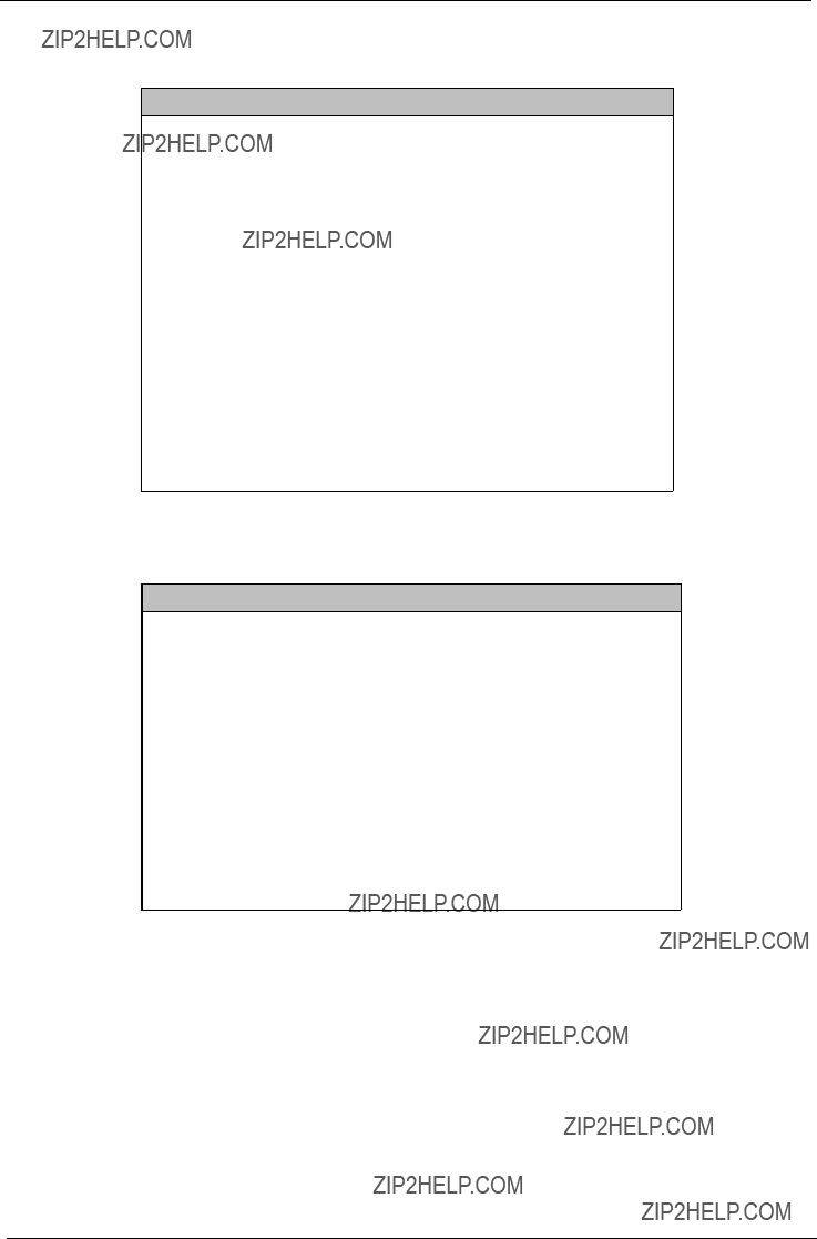
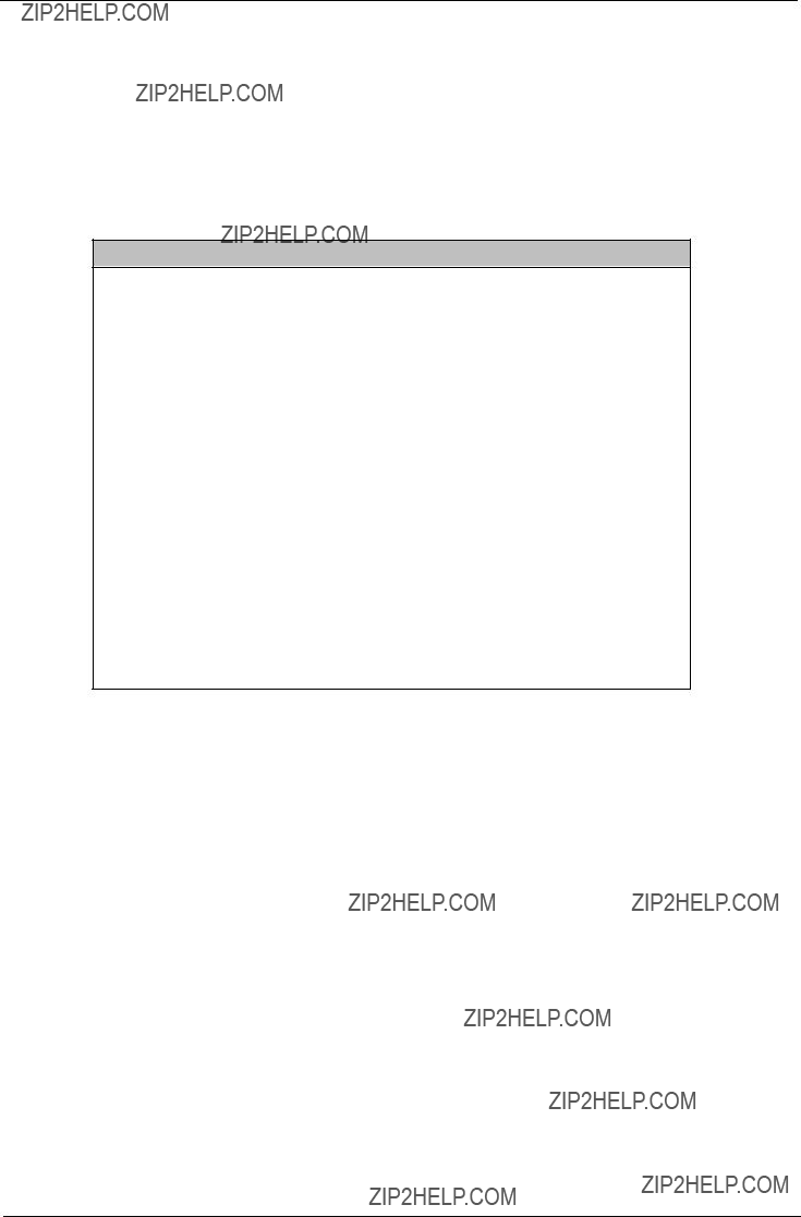
The Setup Utility main menu then appears:
Setup Utility
!System Information
!Product Information
!Disk Drives
!Onboard Peripherals
!Power Management
!Boot Options
!Date and Time
!System Security
Load Default Settings
Abort Settings Change
The system supports two BIOS Utility levels: Basic and Advanced. The above screen is the BIOS Utility Basic Level screen. It allows you to view and change only the basic configuration of your system.
If you are an advanced user, you may want to check the detailed configuration of your system. Detailed system configurations are contained in the Advanced Level. To view the Advanced Level menu, press F8 or the Alt + F4 keys simultaneously.
NOTE: The F8 and Alt + F4 keys work only when you are in the main menu. This means that you can activate the advanced level and hidden information only when you are in the main menu.
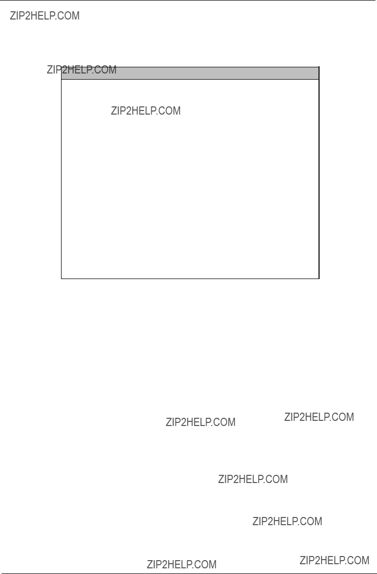
The following screen shows the Advanced Level main menu:
Setup Utility
!System Information
!Product Information
!Disk Drives
!Onboard Peripherals
!Power Management
!Boot Options
!Date and Time
!System Security
!Advanced Options
Load Default Settings
Abort Settings Change

The command line at the bottom of the menu tells you how to move within a screen and from one screen to another.
!To select an option, move the highlight bar by pressing 
 or
or  then press
  .
.
!Press 
 to move to the next page or
 to return to the previous page.
!To change a parameter setting, press 
 or
or 
 until the desired setting is found.
!Press 
 to return to the main menu. If you are already in the main menu, press
 again to exit Setup.
The parameters on the screens show default values. These values may not be the same as those in your system.
The grayed items on the screens have fixed settings and are not

System Information
The following screen appears if you select System Information from the main menu.
This page shows the current basic configuration of your system.
The following table describes the parameters found in the System Information pages:


Product Information
The screen below appears if you select Product Information from the main menu:
Product Information
NOTE: The asterisk (*) mark indicates that the parameter appears only when you are in the Advanced Level.
The Product Information menu contains general data about the system, such as the product name, serial number, BIOS version, etc. These information is necessary for troubleshooting (maybe required when asking for technical support).
The following table describes the parameters found in this menu:

Disk Drives
Select Disk Drives from the main menu to configure the drives installed in your system.
NOTE: The following screen shows the Disk Drives menu:
The asterisk (*) mark indicates that the parameter appears only when you are in the Advanced Level.
!* IDE Primary Channel Master
!* IDE Primary Channel Slave
!* IDE Secondary Channel Master
!* IDE Secondary Channel Slave
The following table describes the parameters found in this menu.
The following screen appears if you select any of the IDE drive parameters:
IDE Primary Channel Master
NOTE: The asterisk (*) mark indicates that the parameter appears only when you are in the Advanced Level.
IDE Primary Channel Slave
IDE Secondary Channel Master
IDE Secondary Channel Slave
NOTE: The asterisk (*) mark indicates that the parameter appears only when you are in the Advanced Level.
The following table describes the parameters found in this menu.


Onboard Peripherals
The Onboard Peripherals menu allows you to configure the onboard devices. Selecting this option from the main menu displays the following screen:
The following table describes the parameters found in this menu.

Power Management
The Power Management menu lets you configure the system
IMPORTANT:If an
The following screen shows the Power Management parameters and their default settings:
Power Management
The following table describes the parameters found in this menu.

Boot Options
This option allows you to specify your preferred settings for bootup.
The following screen appears if you select Boot Options from the main menu:
Boot Options
Boot Sequence
1st. [Floppy Disk A:] 2nd. [Hard Disk C:] 3rd. [IDE
4th. [Intel ?? Boot Agent Version 3.0]
NOTE: The asterisk (*) mark indicates that the parameter appears only when you are in the Advanced Level.
The following table describes the parameters found in this menu.


Date and Time
The following screen appears if you select the Date and Time option from the main menu:
The following table describes the parameters found in this menu:

System Security
The Setup program has a number of security features to prevent unauthorized access to the system and its data.
The following screen appears if you select System Security from the main menu:
System Security
The following table describes the parameters found in this menu.
Setting a Password
3.Enter the BIOS utility and select ???System Security??? .
4.Highlight the ???Supervisor Password??? parameter to set a Setup password, or ???User Password??? to set a
Supervisor Password
Enter your Password twice. The Password
Set or Change Password
5.Type a password. The password may consist of up to seven characters. Then press Enter.
6.Retype the password then press Enter.
7.After setting the password, highlight the ???Set or Change Password??? option.
8.Press Esc to return to the System Security screen. If you have set a Supervisor password (and/or User password), the Supervisor Password (and/or User password) setting automatically changes to Present.
9.Press Esc to return to the Main menu.
10.Press Esc to exit the BIOS utility. A dialog box appears asking if you want to save the CMOS data.
11.Select ???Yes??? to save the changes and reboot the system.
If you have set a Supervisor password, the next time you want to enter the BIOS utility, you must
If you have set a User password, you will be prompted to enter that password every time you boot your system.

Changing or Removing the Password
If you want to change one of your passwords, do the following:
1.Enter the BIOS utility and select ???System Security???.
2.Highlight the ???Supervisor Password??? parameter (for Supervisor password) or the ???User Password??? parameter (a Supervisor Password must be set first before you can change the User password). The Password menu appears.
3.From the Password menu, highlight the ???Set or Change Password??? option.
4.Enter a new password.
5.Press Esc to return to the System Security screen.
6.Press Esc to return to the main menu.
7.Press Esc to exit the BIOS utility. A dialog box appears asking if you want to save the CMOS data.
8.Select ???Yes??? to save the changes.
To remove the password, simply select the ???Supervisor Password??? parameter (for Supervisor password) or the ???User Password??? parameter (a Supervisor Password must be set first before you can change the User password) from the System Security menu and set it to ???None???.
Bypassing the Password
If you forgot your password, you can bypass the password security feature thru hardware configuration.
RTC Battery
Follow these steps to bypass the password:
1.Turn off and unplug the system.
2.Open the system housing. Take off battery and short it.
3.Place on RTC battery, reboot the system and enter setup menu, to load default setting.
Clear CMOS
Follow these steps to bypass the password:
1.Reset CMOS, by adjusting JPX1 to
2.Reboot the system.
3.Adjust the JPX1 back to
Password Check
Follow the step to bypass the password: 1. Adjust JPXB to

Advanced Options
NOTE: The Advanced Options menu is only available if you press F8 or Alt + F4 in the main menu. The ???Advanced Options??? menu allows you to configure the system memory and PCI device settings. The following screen shows the Advanced Options parameters:
Advanced Options
!Memory/Cache Options
!PnP/PCI Options
CAUTION: Do not change any settings in the Advanced Options menu if you are not a qualified technician to avoid damaging the system.
Memory/Cache Options
Selecting ???Memory/Cache Options??? from the Advanced Options menu displays the following screen: This menu lets you configure the system memory.
Memory/Cache Options
The following table describes the parameters found in this


PnP/PCI Options
The PnP/PCI Options menu allows you to specify the settings for your PCI devices. Selecting this option displays the following screen:
PnP/PCI Options
The following table describes the parameters found in this
Chipset Settings
The Chipset Settings will be shown only if you press Alt + F4 in main menu:
Advanced Options
!Memory/Cache Options
!PnP/PCI Options
!*Chipset Settings
Press Enter to view the Chipset settings information.
The following screen displays the Chipset settings menu:
Chipset Settings
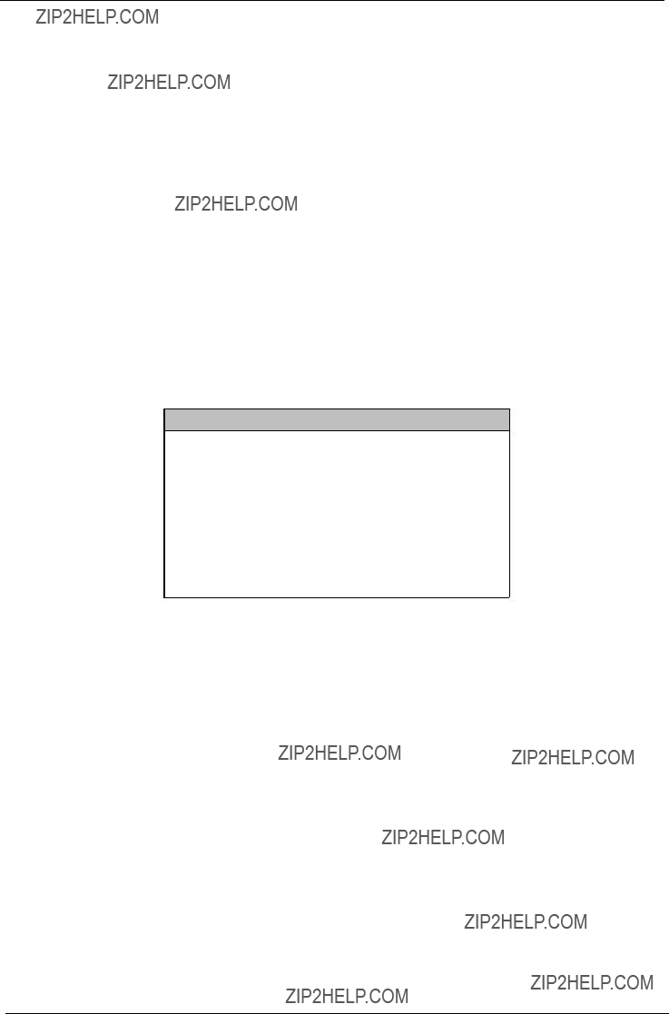
Load Default Settings
You need to reload the BIOS default settings every time you make changes to your system hardware configuration (such as memory size, CPU type, hard disk type, etc.); otherwise, BIOS will keep the previous CMOS settings. Selecting this option displays the following dialog box:
Load Default Settings
Do you want to load default settings?
[Yes] *[No]
Choosing Yes enables BIOS to automatically detect the hardware changes that you have made in your system. This option also allows you to restore the default settings.
Choosing No returns you to the main menu without loading the default settings.

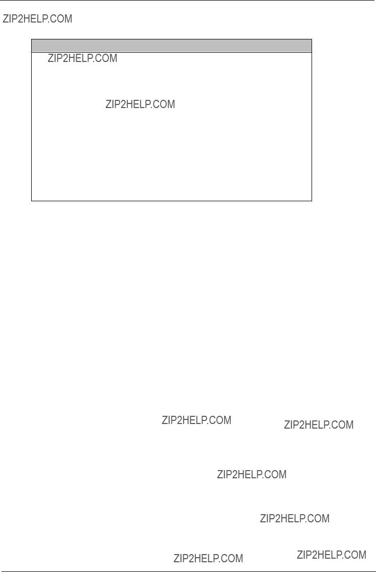
Abort Settings Change
Selecting the Abort Settings Change option from the main menu displays the following dialog box:
Abort Settings Change
Do you really want to abort settings change?
*[Yes] [No]
Choosing Yes discards all the changes that you have made and reverts the parameters to their previously saved settings.
Choosing No returns you to the main menu. BIOS retains all changes that you have made.
Exiting Setup
To exit the BIOS utility, simply press Esc. The following dialog box appears:
Exit Setup
Settings have been changed.
Do you really want to exit setup?
*[Yes] [No]
Select Yes to exit Setup. Select No to return to the main menu.
Exit Setup
Settings have been changed.
Do you want to save CMOS settings?
*[Yes] [No]
If you have made changes in the parameter settings, you will be asked if you want to keep the changes made to the BIOS. Select Yes to save your changes before you exit Setup. Select No to discard all changes and exit Setup.
Chapter 3
Machine Disassembly and Replacement
This chapter contains 2 separate
To disassemble the computer, you need the following tools:
Wrist grounding strap and conductive mat for preventing electrostatic discharge
Phillips screwdriver
Hexagonal screwdriver
Plastic stick
NOTE: The screws for the different components vary in size. During the disassembly process, group the screws with the corresponding components to avoid mismatches when putting back the components.

Disassembling the Veriton 5100
Removing the Housing Cover
CAUTION: Before you proceed, make sure that you have turned off the system and all peripherals connected to it.
1.Turn off the system power and unplug all cables.
2.Place the system unit on a flat, steady surface.
3.Turn the thumbscrews counterclockwise to remove the cover. Set the screws aside. You will need the when replacing the housing cover.
4.Hold the sides of the cover with both hands. Slide it back about an inch and then gently pull it outward to detach it.

Removing a Link Bar
1.To remove a link bar, remove the screw that secures it to the housing.
2.Then gently lift the link bar and pull it out.
Removing a DIMM
1.Press the latches on both sides of the DIMM socket outward, to release the DIMM.
2.Then gently lift the DIMM out to remove it.

Removing the Processor
Follow these steps to remove the processor:
1.Detach the fan/heatsink cable connector .
2.Remove the fan/heatsink from the processor.
3.Pull the socket lever up to release the processor pins from the socket holes.
4.Pull out the processor from the socket.
.
WARNING:The heatsink becomes very hot when the system is On. Never touch the heatsink with any metal or with your hands.

Removing the Hard Disk Drive and
Follow these steps to remove the hard disk drive:
1.Detach the power and disk drive cables from the hard disk and diskette drive.
2.Remove the screw that secures the link bar to the housing.
3.Lift up the link bar and pull it out.
4.Remove the four screws that hold the hard disk drive to the disk frame and detach the hard disk drive. Set the screws aside.

5.Remove the four screws that hold the diskette drive to the disk frame and pull out the diskette drive.
Removing the
1.Remove the four screws that hold the
Removing the PCI and AGP Expansion Cards
1.Remove the screw on the bracket of an expansion card. Set the screw aside. You will need it when replacing the expansion card.
2.Gently pull out the expansion card to remove it from the expansion slot.
NOTE: When you turn on the system, BIOS automatically detects and assigns resources to the PCI devices.

Removing the Power Supply
1.Remove the four screws that hold the power supply to the housing and pull out the power supply.
Disassembling the Veriton 7100
Opening the Housing
This section tells you how to open the housing cover when you need to install additional components inside the system unit.
CAUTION: Before you proceed, make sure that you have turned off the system and all peripherals connected to it.
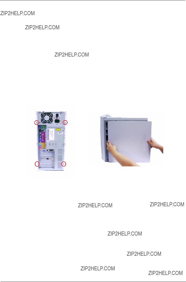
Removing the Housing Cover
1.Turn off the system power and unplug all cables.
2.Place the system unit on a flat, steady surface.
3.Remove the four screws of the right panel using a screwdriver. Set the screws aside, you will need the when replacing the right panel of the unit.
4.Slide the right panel out and then gently pull it outward to detach it from the housing. Do the same for the left panel.

Removing the Front Panel
1.Release the 6 latches as shown below that holds the front panel and then it from the housing.
Removing a DIMM
1.Press the latches on both sides of the DIMM socket outward, to release the DIMM.
2.Then gently lift the DIMM out to remove it.
Removing the Processor
Follow these steps to remove the processor:
1.Detach the fan/heatsink cable connector .
2.Remove the fan/heatsink from the processor.
3.Pull the socket lever up to release the processor pins from the socket holes.
4.Pull out the processor from the socket.
.
WARNING:The heatsink becomes very hot when the system is On. Never touch the heatsink with any metal or with your hands.
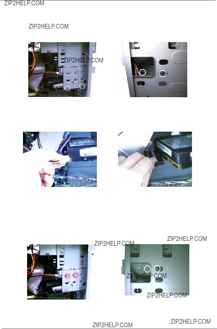
Removing the Hard Disk
Follow these steps to remove the hard disk drive:
1. Remove the four screws that hold the hard disk drive to the disk frame. Set the screws aside.
.
2.Detach the power and disk drive cables from the hard disk drive, then detach the hard disk from the drive frame.
.
Removing the Diskette Drive
Follow these steps to remove the diskette drive:
1. Remove the four screws holding the diskette drive.

2. Disconnect the power connector and the diskette drive cable, then remove the diskette drive from the housing.
Removing the
Follow these steps to remove the
1. Remove the four screws holding the
2.Disconnect the power connector,

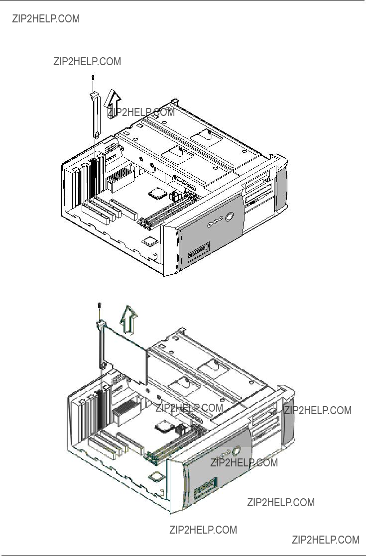
Removing the PCI and AGP Expansion Cards
1.Remove the screw on the bracket of the expansion card. Set the screw aside, you will need it when replacing the expansion card.
2.Gently pull out the expansion card to remove it from the expansion slot.
.
NOTE: When you turn on the system, BIOS automatically detects and assigns resources to the PCI or AGP devices.

Removing the Audio Board
1. Disconnect the audio cable and the USB cable from the audio board.
2.Remove the 2 screws that hold the audio board, then remove it from the housing.

Removing the System Main Board
1.Put the housing to lying position with the open area facing upward.
2.Remove the seven screws holding the main board and then remove the main board from the housing.
Removing the Power Supply
1.Disconnect the power supply power connector from the main board.
2.Remove the four screws holding the power supply, and then remove the power supply from the housing..
Removing the Intrusion Alarm
1.Remove the screw that secures the intrusion alarm and then remove it from the housing.

Chapter 4
Troubleshooting
This chapter provides troubleshooting information for the Veriton 5100/7100:
!
!Index of Error Messages
!Index of Error Codes and Error Beeps
!Index of Error Symptoms
!Undetermined Problems

Each time you turn on the system, the
The
The main components on the main board that must be diagnosed and/or initialized by POST to ensure system functionality are as follows:
!Microprocessor with
!Direct Memory Access (DMA) controller
!Interrupt system
!Three programmable timers
!ROM subsystem
!RAM subsystem
!RTC RAM subsystem and real time clock/calendar with battery backup
!Onboard serial interface controller
!Onboard parallel interface controller
!Embedded hard disk interface and one diskette drive interface
!Keyboard and auxiliary device controllers
!I/O ports
!
!
!Serial ports
!Parallel ports
!USB port

POST Error Messages List
If you cannot run the diagnostics program tests but did receive a POST error message, use ???POST Error Messages List??? to diagnose system problems. If you did not receive any error message, look for a description of your error symptoms in ???Error Symptoms List??? on page 75.
NOTE: When you have deemed it necessary to replace an FRU, and have done so, you must run a total system check to ensure that no other activity has been affected by the change. This system check can be done through the diagnostics program.
NOTE: Check all power supply voltages, switch, and jumper settings before you replace the main board. Also check the power supply voltages if you have a ???system
If you are unable to correct the problem by using the ???BIOS Messages List??? table and ???Error Symptoms List??? table, go to ???Undetermined Problems??? on page 79.
NOTE: To diagnose a problem, first find the BIOS error messages in the left column. If directed to a check procedure, replace the FRU indicated in the check procedure. If no check procedure is indicated, the first Action/FRU listed in right column is the most likely cause.

Error Symptoms List
NOTE: To diagnose a problem, first find the error symptom in the left column. If directed to a check procedure, replace the FRU indicated in the check procedure. If no check procedure is indicated, the first Action/ FRU listed in right column is the most likely cause.
NOTE: Normally, the processor fan should be operative, and the processor clock setting should be exactly set to match its speed requirement before diagnosing any processor problems.
Diskette Drive
NOTE: Ensure the diskette drive is configured correctly in BIOS Setup and its read/write head is clean before diagnosing any diskette drive problems.

Hard Disk Drive
NOTE: Ensure hard disk drive is configured correctly in BIOS Setup, cable/jumper are set correctly before diagnosing any hard disk drive problems.
NOTE: Ensure


Execute ???Load BIOS Default Settings??? in BIOS Setup to confirm ports presence before diagnosing any parallel/serial ports problems.

Undetermined Problems
If an error message is present, go to ???POST Error Messages List??? on page 73. If you did not receive any messages, see if the symptom is listed in ???or ???Error Symptoms List??? on page 75. If you still cannot solve the problem, continue with this check:
1.Check the power supply voltages. If the voltages are correct continue with the following steps:
2.Power off the system unit.
3.Perform the following checks, one by one, until you have isolated the problem FRU.
4.Load default settings in setup.
5.Check all system board jumper positions and switch settings.
6.Check all adapter card jumper positions.
7.Check all device jumper positions.
8.Check all cables and connectors for proper installation.
9.If the jumpers, switches and voltage settings are correct, remove or disconnect the following, one at a time:
10.
!External devices
!Any adapter card (modem card, LAN card or video card, if installed)
!
!Diskette drive
!Hard disk drive
!DIMM
!Processor
!System board
11.Power on the system unit.
12.Repeat steps 2 through 5 until you find the failing device or adapter.

Chapter 5
Jumper and Connector Information
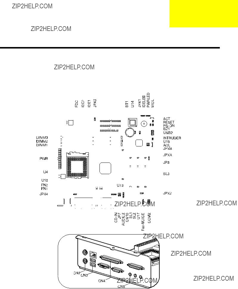
Jumpers and Connectors
Refer to the following figure for the location of the jumpers and connectors on the main board:
Main board

Connector Description

Jumper Setting
NOTE: *: Default Settings

Audio Board
Chapter 6
FRU (Field Replaceable Unit) List
This chapter gives you the FRU (Field Replaceable Unit) listing in global configurations of Veriton 5100/7100. Refer to this chapter whenever ordering for parts to repair or for RMA (Return Merchandise Authorization).
IMPORTANT: Please note WHEN ORDERING FRU PARTS, that you should check the most
NOTE: To scrap or to return the defective parts, you should follow the local government ordinance or regulations on how best to dispose it, or follow the rules set by your regional Acer office on how to return it.
NOTE: The number indicates the location shown on exploded diagram or ???NS??? indicates ???Not shown??? on it.
85

Veriton 5100 Exploded Diagram

Veriton 7100 Exploded Diagram


Appendix A
Model Definition and Configuration
Veriton 5100
The Veriton 5100 Model No. Define:
1.Trade Mark:
2.Brand Name: Acer
3.Description: Acer Veriton Series, PIII & Celeron Socket 370 Based PC System
4.Model No: VT5100
5.Product Name: Veriton 5100

Veriton 7100
The Veriton 7100 Model No. Define:
1.Trade Mark:
2.Brand Name: Acer
3.Description: Acer Veriton Series, PIII & Celeron Socket 370 Based PC System
4.Model No: VT7100
5.Product Name: Veriton 7100

Appendix B
Test Compatible Components
This computer???s compatibility is tested and verified by Acer???s internal testing department. All of its system functions are tested under MS DOS V6.22, Microsoft Windows 98 SE (EN/TW), Microsoft Windows 2000 Professional, Microsoft Win95/NT 4.0 Workstation, IBM OS/2 Warp 4.0, Novell Netware 4.12 & 5.1, and SCO UNIX/Red Hat Linux environment.
Refer to the following lists for components, adapter cards, and peripherals which have passed these tests. Regarding configuration, combination and test procedures, please refer to the Veriton 5100/7100 Compatibility Test Report released by the Acer Desktop System Testing Department.

MS DOS V6.22 Environment Test

Microsoft Windows 98SE (EN/TW) Environment Test


Microsoft Windows 2000 Professional Environment Test

Microsoft Win95/NT 4.0 Workstation Environment Test
IBM OS/2 Warp 4.0 Environment Test

Novell Netware 4.12 & 5.1 Environment Test

SCO UNIX/Red Hat Linux Environment Test


Appendix C
Online Support Information
This appendix describes online technical support services available to help you repair your Acer Systems.
If you are a distributor, dealer, ASP or TPM, please refer your technical queries to your local Acer branch office. Acer Branch Offices, Regional Offices and Regional Group may access our website. However, some information sources will require a user I.D. and password. These can be obtained directly from Acer CSD Taiwan.
Acer's Website offers you convenient and valuable support resources whenever you need them. You can get the information on all of Acer's Notebook, Desktop and Server models including;
!Service guides for all models
!User's manuals
!Training materials
!BIOS updates
!Software utilities
Also contained on this website are:
!Detailed information on Acer's International Traveler's Warranty (ITW)
!An overview of all the support services we offer, accompanied by a list of telephone, fax and
Here is the Acer headquarters??? Customer Service Division Internet address for your support information:
http://csd.acer.com.tw
If you have any suggestions or comments, please do not hesitate to communicate these to: GCSDlifeline@acer.com.tw, or fax to (886) 2 86911799.


Index
A
AGP
AGP Expansion Cards 61 Assignment Map 21 Audio
controller 19 Audio Board 84 Audio Interface 19
B
Entering Setup 28 Setup Utility 28
Abort Settings Change 53 Advanced Options 47 Boot Options 41
boot sequence 41 fast boot 41 memory test 42
Num Lock after boot 42 silent boot 41
C
Chipset Settings 50 System Utilities 50
Chipsets 23 CMOS Setup 27 Compatibility Test 99 Connectors 81
audio 19 serial port 20 video 18
CPU
removing 57, 58, 65 CPU upgrade
removing 57, 58, 65 CRT Monitor port 7, 11 Current 24
D
Device Standby Mode 25 Dimensions 23 disassembly
Power Supply 62 Disk Drives 33
DMA transfer mode 36 floppy drives A/B 33
Hard disk
Diskette Drive removing 66

E
Environmental Requirements 23 EPP 20
Error Sysmptoms List 75 Expansion Cards
removing 68 Expansion slot 7, 11
F
connectivity 2 design 3 ergonomics 3 Multimedia 2 Performance 2
Floppy disk drive Interface 19 Frequency 24
G
H
Hard Disk
Hardware Specifications and Configurations 16
HDD
I
Interface
J
Jumper and Connector Information 81
K
cursor keys 14 lock keys 14
L
M
Main Board Layout 12 Mechanical Specifications 23 Memory
Memory Address Map 21 Memory/Cache Options 47
external cache 47 internal cache 47
Motherboard removing 70
N
Netware 3.12, 4.11 & 5.0 Environment Test 106 Network port 10
O

operation mode 37 serial port 1/2 37
Online Support Information 109 Overview 1
P
Parallel Port 20 Parallel/printer port 7, 10 Password
bypassing 46 changing 46 removing 46 setting 45 Setup 44
PCI
PCI Expansion Cards 61 PCI INTx# 21
PCI Slot IRQ 21 ports
Power button 5, 8 Power cord socket 7, 10 Power LED 5, 8
IDE hard disk timer 39 modem ring indicator 40 modes 39
power switch > 4 seconds 40 Sleep mode 39
system sleep timer 39 system
Power Supply removing 70
removing 57, 58, 65 Product Information 32
DMI BIOS version 32 main board ID 32 product name 32 system BIOS version 32 system serial number 32
PS/2 keyboard port 7, 10 PS/2 mouse port 7, 10
R
Removal and Replacement 55 removing 57, 58, 65 Replacement
Assembly, Machine 55 replacing HDD 59
RIMM
S
SCO UNIX/Linux Environment Test 107 Security 44
disk drive control 44 floppy drive 44 hard disk drive 44 Setup password 44
Serial Port 20 Serial port 7, 11 socket
memory 17 Socket 370 16 Suspend Mode 25 Switching
Power Supply 102W 24 Symptoms List 75
Audio 77
Other 78 Parallel Port 78 Power Supply 78
Processor / Processor Fan 75
Serial Port 78 System Board 75 Video 77
System 27 System Board
removing 70 System Information

Processor speed 30 PS/2 mouse 31 serial port 1 31 total memory 31
System Memory 56, 64 System Security
Abort Settings Change 53 Advanced Options 47 Boot Options 41
T