
105
System rack installation
Aside from its tower configuration, the Altos G701 server system can also be mounted in a
The figure below shows the Altos G701 server in a
Appendix B
Rack installation guide
This appendix shows you how to install the ASM and RDM software package.
105
System rack installation
Aside from its tower configuration, the Altos G701 server system can also be mounted in a
The figure below shows the Altos G701 server in a

Vertical mounting hole pattern
The four vertical rails of a rack contain mounting holes arranged in a manner shown in the figure below:
The system occupies 5U in the rack. Count the U positions and hole numbers from the bottom up.
Note: The unit of measurement used in this document is "U" (1U = 1.75 inches or 44.45 mm). The total sum of the heights of all components in the rack measured in "U" cannot exceed the height of the rack. For more information, refer to the documentation that came with your system rack.
The distance from the center of two holes with closer spacing to the center of the next pair is equivalent to 1U.
When installing components, you must start your measurement from the center of the two holes with closer spacing. Otherwise, the screw holes on the component may not match those on the rack.

103
Screw types for rack installation
The following screws are used in the assembly of the Acer Altos G701 and other
Hex head
Cage nut
Attaching the side handles to the server
Supports the M6 metal screws for securing server components to the rack

Installing cage nuts
Cage nuts are use to secure systems and other components to the vertical rails in the rack.
To install cage nuts:
1Insert the lower lip of the cage nut over the bottom of the opening at the back of a rail.
2Insert the small end of the
3Push in the cage nut while rotating the tool up and pulling the tool back toward you until the top lip of the cage nut snaps into position.
4Repeat this process to install the other cage nuts in their appropriate locations.

105
Installing the system into the rack
To install the system into the rack:
1Remove the front bezel from the server. Refer to ???Removing the front bezel??? on page 33 for instructions.
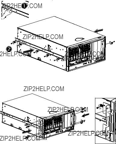
2Remove the top panel of the server.
(1)Use a screw driver to remove the two rear screws holding the top panel to the chassis.
(2)Slide the top panel backward to detach it from the chassis.
3Remove the rubber foot stands from the server.
(1)Lay the server on its side on a flat, stable surface.
(2)Use the flat side of a screw driver to remove the plug from the foot stands. Keep these plugs for later use.

(3)Pull out the rubber stands from the server.
There are two sets of rack bracket and mounting rail. The rack brackets are used to attached the mounting rails to the server. Each bracket is composed of three pieces: a detachable inner rail and a fixed middle and outer rails. The mounting rails allow the system to slide in and out of the rackmount for maintenance purposes.
4Remove the inner rail from the rack brackets.
(1)Extend the inner rail until the rail release latch clicks.
(2)Hold down the latch then slip the inner rail out.

107
Do the same thing to the other rack bracket.
5Attach the inner rails to the top and bottom side of the server.
(1)Align the inner rail to the five screw holes located on the bottom side of the server.
(2)Secure the rail to the server using M4 x L5 screws.
Attach the other inner rail to the top side of the server.
6Attach the two side handles to the server using four hex head screws for each handle.
7Set the server aside.
8Attach the rack brackets to the mounting rails.
a Align the rack brackets to the mounting rail until the six screw holes become visible.
b Secure the rack bracket to the mounting rail using M4 x L8 screws. Tighten the screws loose enough to allow length adjustment when installing the mounting rails to the rack.
109
Attach the other rack bracket to the remaining mounting rail.
9Install the mounting rails to the rack using four M6 x L10 screws for each mounting rail.

10Extend the middle sliding piece of each mounting rail forward until it clicks.
11Install the server into the rack by first carefully aligning the inner rails attached to the server with the mounting rails on the rack.
(1)Press the release latch on both sides of the server.
(2)Slide the server into the rack then push the server into the rack until it clicks.

111
Caution! To avoid personal injury, care should be taken when pressing the component rail release latches and sliding the component into the rack.