AcerPower 6000

User???s Guide

Document

History

Copyright

Notice

Trademarks

Disclaimer

Copyright ?? 1996, 1997, 1998 by Acer America Corporation. All rights reserved. No part of this publication may be reproduced, transmitted, transcribed, stored in a retrieval system, or translated into any language or computer language, in any form or by any means, electronic, mechanical, magnetic, optical, chemical, manual or otherwise, without the prior written permission of Acer America Corporation.

Programs Copyright ?? 1996, 1997, 1998 Acer America Corporation.

All rights reserved.

Printed in U.S.A

Acer and the Acer logo are registered trademarks of Acer Incorporated.

Intel is a registered trademark of Intel Corporation.

Windows, Windows NT, Windows 95, Windows 98, and DOS are registered trademarks of Microsoft Corporation.

Other brand and product names are trademarks or registered trademarks of their respective holders.

Acer and its suppliers make no representations or warranties, either expressed or implied, with respect to the contents hereof and specifically disclaim any warranties of merchantability or fitness for a particular purpose. Further, Acer reserves the right to revise this publication and to make changes from time to time in the contents hereof without obligation to notify any person of such revisions or changes. Acer reserves the right to make changes to the products described in this manual at any time and without notice.

ii AcerPower 6000 User???s Guide

Warranty/Limitation of Liability

Any software described in this manual is licensed "as is" and Acer and its suppliers disclaim any and all warranties, express or implied, including but not limited to any warranty of non-infringement of third party rights, merchantability or fitness for a particular purpose. Acer does not warrant that the operation of the software will be uninterrupted or error free. Should the programs prove defective, the buyer (and not Acer, its distributor, or its dealer) assumes the entire cost of all necessary service, repair, and any incidental or consequential damages resulting from any defect in the software. Please see the Acer Limited Product Warranty for details of Acer???s limited warranty on hardware products.

IN NO EVENT SHALL ACER BE LIABLE FOR ANY INDIRECT OR CONSEQUENTIAL DAMAGES,

INCLUDING LOSS OF PROFITS OR DATA, EVEN IF ACER HAS BEEN ADVISED OF THE

POSSIBILITY OF SUCH DAMAGES.

Software License

Acer grants you a personal, non-transferable, non-exclusive license to use the software that accompanies your computer system only on a single computer. You may not (a) make copies of the software except for making one (1) backup copy of the software which will also be subject to this license, (b) reverse engineer, decompile, disassemble, translate or create derivative works based upon the software, (c) export or re-export the software to any person or destination which is not authorized to receive them under the export control laws and regulations of the United States, (d) remove or alter in any way the copyright notices, or other proprietary legends that were on the software as delivered to you or (e) sublicense or otherwise make the software available to third parties. The software is the property of Acer or Acer???s supplier and you do not have and shall not gain any proprietary interest in the software (including any modifications or copies made by or for you) or any related intellectual property rights. Additional restrictions may apply to certain software titles. Please refer to any software licenses that accompany such software for details.

Join Us to Fight Against Piracy

The Acer Group has been implementing a policy to respect and protect legitimate intellectual property rights. Acer firmly believes that only when each and every one of us abides by such policy, can this industry provide quality service to the general public.

Acer has become a member of the Technology Committee of the Pacific Basin Economic Council which is encouraging the protection and enforcement of legitimate intellectual property rights worldwide. Moreover, in order to ensure quality service to all of our customers, Acer includes an operating system in Acer computer systems which is duly licensed by the legitimate proprietors and produced with quality.

Acer commits itself and urges all of its customers to join the fight against intellectual property piracy wherever it may occur. Acer will pursue the enforcement of intellectual property rights and will strive to fight against piracy.

iii

IMPORTANT SAFETY INSTRUCTIONS

1.Read these instructions carefully. Save them for future reference.

2.Follow all warnings and instructions marked on the product.

3.Unplug this product from the wall outlet before cleaning. Do not use liquid or aerosol cleaners. Use a damp cloth for cleaning.

4.Do not use this product near water.

5.Do not place this product on an unstable cart, stand, or table. The product may fall, causing serious damage to the product.

6.Slots and openings in the cabinet and the back or bottom are provided for ventilation; to ensure reliable operation of the product and to protect it from overheating, these openings must not be blocked or covered. This product should never be placed near or over a radiator or heat register, or in a built-in installation unless proper ventilation is provided.

7.This product should be operated from the type of power indicated on the marking label. If you are not sure of the type of power available, consult your dealer or local power company.

8.This product is equipped with a 3-wire grounding-type plug, a plug having a third (grounding) pin. This plug will only fit into a grounding-type power outlet. This is a safety feature. If you are unable to insert the plug into the outlet, contact your electrician to replace the outlet. Do not defeat the purpose of the grounding-type plug.

9.Do not allow anything to rest on the power cord. Do not locate this product where persons will walk on the cord.

10.If an extension cord is used with this product, make sure that the total ampere rating of the equipment plugged into the extension cord does not exceed the extension cord ampere rating. Also, make sure that the total rating of all products plugged into the wall outlet does not exceed 15 amperes.

iv AcerPower 6000 User???s Guide

11.Never push objects of any kind into this product through cabinet slots as they may touch dangerous voltage points or short out parts that could result in a fire or electric shock. Never spill liquid of any kind on the product.

12.Do not attempt to service this product yourself, as opening or removing covers may expose you to dangerous voltage points or other risks. Refer all servicing to qualified service personnel.

13.Unplug this product from the wall outlet and refer servicing to qualified service personnel under the following conditions:

a.When the power cord or plug is damaged or frayed

b.If liquid has been spilled into the product

c.If the product has been exposed to rain or water

d.If the product does not operate normally when the operating instructions are followed. Adjust only those controls that are covered by the operating instructions since improper adjustment of other controls may result in damage and will often require extensive work by a qualified technician to restore the product to normal condition.

e.If the product has been dropped or the cabinet has been damaged

f.If the product exhibits a distinct change in performance, indicating a need for service

v

14.Use only the proper type of power supply cord (provided in your keyboard/manual accessories box) for this unit. It should be a detachable type: UL listed/CSA certified, type SVT/SJT, rated 6A 125V minimum. Maximum length is 15 feet (4.6 meters).

15.Replace battery with the same type as the product???s battery we recommend. Use of another battery may present a risk of fire or explosion. Refer battery replacement to a qualified technician.

The battery may explode if not handled properly. Do not recharge, disassemble or dispose of in fire. Keep away from children and dispose of used battery promptly.

vi AcerPower 6000 User???s Guide

FCC Class B Radio Frequency

Interference Statement

Note:

This equipment has been tested and found to comply with the limits for a Class B digital device, pursuant to Part 15 of FCC Rules. These limits are designed to provide reasonable protection against harmful interference in a residential installation. This equipment generates, uses, and can radiate radio frequency energy and, if not installed and used in accordance with the instructions, may cause harmful interference to radio communications. However, there is no guarantee that interference will not occur in a particular installation. If this equipment does cause harmful interference to radio or television reception, which can be determined by turning the equipment off and on, the user is encouraged to try to correct the interference by one or more of the following measures:

1.Reorient or relocate the receiving antenna.

2.Increase the separation between the equipment and receiver.

3.Connect the equipment into an outlet on a circuit different from that to which the receiver is connected.

4.Consult the dealer or an experienced radio/television technician for help.

Notice 1:

The changes or modifications not expressly approved by the party responsible for compliance could void the user's authority to operate the equipment.

Notice 2:

Shielded interface cables, if any, must be used in order to comply with the emission limits.

vii

CD-ROM Safety Warning

DANGER

INVISIBLE RADIATION WHEN OPEN.

AVOID EXPOSURE TO BEAM.

Caution on Lithium Batteries

CAUTION

Danger of explosion if battery is incorrectly replaced. Replace only with the same or equivalent type recommended by the manufacturer. Discard used batteries according to the manufacturer???s instructions.

viii AcerPower 6000 User???s Guide

Table of Contents

Introduction

ix

x AcerPower 6000 User???s Guide

xi

xii AcerPower 6000 User???s Guide

List of Figures

xiii

List of Tables

xiv AcerPower 6000 User???s Guide

Conventions

The following conventions are used in this manual:

xv

Introduction

Acer has been on the leading edge of microcomputer systems development for both corporate and home computing needs for 20 years, as the OEM of choice for many of the world???s leading computer companies. Acer is committed to meeting the world???s demand for state-of-the-art computers ??? at the best prices.

Your AcerPower desktop configuration provides high-speed performance in a small footprint ??? making it perfect for small offices or general business use.

The system board features the common functions offered by a high-performance board. It has a power-management function that conforms to the power-saving standards of the U.S. Environmental Protection Agency (EPA) Energy Star program. It also supports Plug-and-Play features.

Overview

The AcerPower 6000 system supports Intel Pentium processors with MMX (MultiMedia eXtensions) technology and the new Celeron processor. The Celeron processor is Intel's Pentium II cost-down solution. It comes without a second-level cache. It has two ISA and two PCI slots for future expansion. The system memory is expandable to 256 MB via two onboard 168-pin DIMM (double in-line memory module) sockets.

The system also features a 3-D video function with AGP (Accelerated Graphics Port) support and a 3-D audio function.

Aside from the standard I/O (input/output) interfaces such as one serial port, one parallel port, and PS/2 keyboard and mouse ports, the system also offers two USB (Universal Serial Bus) ports, one VGA (Video Graphics Accelerator) port, one Feature connector, one mono Microphone-in port, one stereo Line-in port, one Line-out port, and one Game/MIDI (Musical Instrument Digital Interface) port.

Introduction 1

These additional ports are included to enable the system to accommodate additional peripherals.

The system is fully compatible with MS-DOS V6.X, OS/2, SCO UNIX, Windows NT, and Windows 95/98 operating systems.

About This Manual

This manual is divided into four chapters. A brief description of these chapters is provided below.

Chapter 1 Getting Started

Describes the different parts of the system unit. It tells you how to select a site and set up the basic system. It includes a simple troubleshooting section and a list of system error messages with the corresponding corrective actions.

Chapter 2 System Board

Describes the system board and all its major components. It contains information about the system board layout, jumper settings, jumper and connector locations and functions.

Chapter 3 BIOS Utility

Explains the BIOS and tells how to configure the system by setting BIOS parameters.

Chapter 4 Installing Optional Components

Describes how to remove and replace the system housing, and to install the optional components into the housing. It gives brief instructions accompanied by mechanical illustrations showing how to perform each described procedure.

AcerPower 6000 User???s Guide

Chapter 1 Getting Started

1.1Preinstallation

The preinstallation process involves the following activities:

???Selecting a site

???Unpacking components

1.1.1Selecting a Site

Consider the following when selecting a site for your computer:

???Determine the best site for your system. Cable paths should not run near equipment that might cause electromagnetic or radio frequency interference such as radio transmitters, television sets, copy machines, or heating and air conditioning equipment.

???Route cables away from personnel and equipment traffic.

???Avoid dusty areas and extremes of temperature and humidity.

1.1.2Unpacking Components

Unpack the contents of each box carefully. Save all packing materials in case you need to move or ship the system in the future.

Check that all items are present and in good condition. Contact your dealer immediately if anything is missing or damaged.

Chapter 1 - Getting Started 1-1

1.2Features

The basic configuration consists of a system unit, a keyboard, a CD-ROM drive, a diskette drive, a fixed disk drive and a mouse.

1.2.1Front Panel

Figure 1-1 shows the system unit front panel.

Figure 1-1 Front Panel

1-2 AcerPower 6000 User???s Guide

1.2.2Rear Panel

Figure 1-2 shows the system unit rear panel.

Figure 1-2 Rear Panel

Chapter 1 - Getting Started 1-3

1.3Connecting System Components

Do not turn on the power until you finish connecting the system components. The following sections show how to connect each component to the system.

1.3.1Connecting the Keyboard

Plug the keyboard cable into the keyboard socket on the rear panel. See Figure 1-3.

Figure 1-3 Connecting the Keyboard

1-4 AcerPower 6000 User???s Guide

1.3.2Connecting the Monitor

Plug the monitor signal cable into the VGA connector on the rear panel.

Figure 1-4 Connecting the Monitor

Chapter 1 - Getting Started 1-5

1.3.3Connecting the Mouse

Plug the mouse cable into the mouse connector on the rear panel.

Figure 1-5 Connecting the Mouse

1-6 AcerPower 6000 User???s Guide

1.3.4Connecting the Printer (Optional)

If you have a parallel printer, connect it to the parallel port on the rear panel. See Figure 1-6.

Figure 1-6 Connecting the Parallel Printer

If you have a serial printer or other serial peripheral, connect it to the serial port (COM1).

Chapter 1 - Getting Started 1-7

1.3.5Complete System Connections

After connecting all the components, plug one end of the power supply cable into the system power socket. Plug the other end of the power supply cable into a wall outlet. Figure 1-7 shows the complete system connections.

Figure 1-7 Complete System Connections

1-8 AcerPower 6000 User???s Guide

1.3.6Connecting Multimedia Components (Optional)

Your system also supports optional multimedia features. Connect multimedia components as shown in Figure 1-8.

Figure 1-8 Connecting Multimedia Components

Chapter 1 - Getting Started 1-9

1.3.7Connecting the Fax/Modem (Optional)

Your system also supports the optional fax/modem feature. Connect the telephone line and handset as shown in Figure 1-9.

Figure 1-9 Connecting the Telephone Line and Handset to the Fax/Modem

1-10 AcerPower 6000 User???s Guide

1.4Turning On Your Computer

After you have connected all peripherals and cables, follow these steps to turn on your computer:

1.Turn on all peripherals connected to the system such as monitor, printer, fax, speakers, etc.

2.Locate the system main power switch on the back of the system unit and turn it on.

3.Press the power button located on the front of the system unit.

When the system finishes booting, the computer is now ready for use.

1.5Turning Off Your Computer

1.Turn off all peripherals connected to the system such as the monitor, printer, fax, speakers, etc.

2.Press the power button located on the front of the system unit for at least four seconds. Quickly pressing the button puts the system in Suspend mode only.

You do not need to turn off the system main power switch on the rear panel. Turn off the system main power switch only:

???

???

if you will not use your system for a long period of time.

if you need to open your system for troubleshooting or upgrading purposes.

If the system main power switch is not available, you must unplug the system.

Chapter 1 - Getting Started 1-11

1.6Troubleshooting

If you encounter a hardware problem, review the following suggestions before calling for service.

General Failure

???Are all cables securely plugged in?

???Are all system components and peripherals turned on?

???Is the system main power switch on?

???Is the power outlet burned out? You may check this by plugging in and turning on some other piece of equipment.

???Are any cables damaged? Are they properly routed and coiled? Entwined cables may cause signal interference.

Front Panel Light Doesn't Work

???Check inside the system unit and make sure that the front panel LED connector is correctly plugged in (refer to section 2.3 Jumpers and Connectors).

"Garbage" or Nothing Appears on the Screen

???Is the monitor turned on? Is the screen brightness adjusted properly?

Never open the monitor case. The CRT monitor retains very high voltage levels, even after the power is turned off. Refer all monitor service to qualified service technicians.

1-12 AcerPower 6000 User???s Guide

Keyboard is Dead

???Is the keyboard cable plugged in? Turn off the system unit and plug in the keyboard.

Do not plug or unplug the keyboard while the power is on.

Printer Doesn't Work

???Is the printer power turned on?

???Is the printer cable connected to the correct port (serial or parallel)? Is the pin signal interface correct?

???Are your application and the printer configured for the same operating values? Be sure there is no conflict with any port on the add-on card.

???Is the printer out of paper or jammed? Check the printer???s status indicator lights.

???Are the printer cables tangled? To prevent signal interference, neatly fold or coil excess cable length.

Add-on Card Fails Intermittently

???Do two add-on cards have conflicting addresses?

If You Receive an Error Message

???Read the corrective actions in Table 1-1 in section 1.7.

Chapter 1 - Getting Started 1-13

1.7Error Messages

In the event that you receive an error message, do not continue using the computer. Note the message and take corrective action immediately. This section describes the different types of error messages and suggests corrective measures.

There are two general types of error messages:

???Software

???System

1.7.1Software Error Messages

Software error messages are returned by your operating system or application. These messages typically appear after you boot the operating system or when you run your applications. If you receive this type of message, consult your application or operating system manual for help.

1.7.2System Error Messages

A system error message indicates a problem with the computer itself. These messages normally appear during the power-on self-test, before the operating system prompt appears. Table 1-1 lists the system error messages.

1-14 AcerPower 6000 User???s Guide

Table 1-1 System Error Messages

Chapter 1 - Getting Started 1-15

1-16 AcerPower 6000 User???s Guide

1.7.3Correcting Error Conditions

As a general rule, the "Press F1 to continue" error message is caused by a configuration problem which can be easily corrected. An equipment malfunction is more likely to cause a fatal error, i.e., an error that causes complete system failure.

Here are some corrective measures for error conditions:

1.Run Setup. You must know the correct configuration values for your system before you enter Setup, which is why you should write these values down when the system is correctly configured. An incorrect Setup configuration is a major cause of power-on error messages, especially for a new system.

2.Remove the system cover according to the directions in the system housing installation guide. Check that the system board and any expansion boards are set correctly.

3.Check that all connectors and boards are secure. Consult the system housing installation guide for assistance.

If you have purchased a new hard disk drive and cannot access it, it may be because your disk is not physically formatted. Physically format the disk using the FDISK and FORMAT commands.

If you follow the corrective steps above and still receive an error message, the cause may be an equipment malfunction.

If you are sure that your configuration values are correct and your battery is in good condition, the problem may lie in a damaged or defective chip. Contact an authorized service center for assistance.

Chapter 1 - Getting Started 1-17

Chapter 2 System Board

This chapter describes the system board and all its major components, including:

???Details about the system board layout

???Jumper and connector locations and functions

???Jumper settings

The V65MA system board supports the Intel Pentium II processor with MMX (MultiMedia eXtensions) technology and the Celeron processor. The Pentium II comes in a card design with 256- or 512-KB second-level cache already integrated. The Celeron processor is Intel's Pentium II cost-down solution. It comes without second-level cache. Both are capable of handling multimedia functions and enhancing the performance of 32-bit applications.

The system memory is upgradable to 256 MB via the two onboard 168-pin DIMM (Double In-line Memory Module) sockets. These sockets accommodate 8-, 16-, 32-, 64- and 128-MB DIMMs.

The board also incorporates a 3-D video controller with AGP (Accelerated Graphics Port), 2- or 4-MB SGRAM (Synchronous Graphics Random Access Memory), and a 3-D audio controller to fully support multimedia functions.

Onboard I/O (input/output) interfaces are comprised of a UART (Universal Asynchronous Receiver-Transmitter) 16C550 serial port, a parallel port with SPP (Standard Parallel Port)/ECP (Extended Capabilities Port)/EPP (Enhanced Parallel Port) support, and PS/2 keyboard and mouse ports. Two USB (Universal Serial Bus) ports, one VGA (Video Graphics Accelerator) port, one Feature connector, one mono Microphone-in port, one stereo Line-in port, one Line-out port, and one Game/MIDI (Musical Instrument Digital Interface) port are also added to the board design to enable the system to support additional peripherals.

For expansion, the board comes with two ISA (Industry Standard Architecture) slots and two PCI (Peripheral Component Interface) slots.

Chapter 2 - System Board 2-1

Special features such as PnP (Plug-and-Play) support, Power Management, Wireless Communication, Hardware Monitoring, Wake-on Ring, and Wake-on LAN (Local Area Network) functions are also supported. These functions are individually discussed in this chapter.

The system is fully compatible with MS-DOS V6.X, OS/2, SCO UNIX, Windows NT, and Windows 95/98 operating systems.

2.1Major Components

The system board has the following major components:

???A CPU (Central Processing Unit) connector that supports either of the following:

???Pentium II processor running at 266, 300, or 333 MHz

???Celeron processor running at 266 MHz

???Supports 256- or 512-KB PBSRAM (PBSRAM - Pipelined-burst Sychronous Random Access Memory) second-level cache (incorporated in Pentium II) and cacheless designs (0 KB for Convington processor)

???Two DIMM sockets that accept 8-, 16-, 32-, 64-, and 128-MB Standard DRAMs, with Parity Check or Error Correction Code (ECC) feature. These sockets allow memory upgrade of up to 256 MB

???PCI local bus IDE (Integrated Device Electronics) controller

???3-D audio controller

???AGP-compliant 3-D video graphics accelerator with 2- or 4-MB SGRAM

???One Feature connector

???One Wake-on LAN connector

???One Modem ring-in connector

2-2 AcerPower 6000 User???s Guide

???One Modem connector

???One reserved IrDA (InfraRed Data Association) connector

???Two PCI enhanced IDE interfaces that support up to four IDE devices

???External ports

???PS/2 keyboard and mouse ports

???One buffered high-speed serial port

???One SPP/ECP/EPP high-speed parallel port

???Two USB ports

???One standard VGA port

???One mono Microphone-in port

???One stereo Line-in port

???One stereo Line-out port

???One Game/MIDI port

???Two ISA and two PCI slots (one PCI-/ISA-shared)

Chapter 2 - System Board 2-3

2.2Layout

Figure 2-1 shows the locations of the major components on the system board.

Figure 2-1 System Board Layout

2-4 AcerPower 6000 User???s Guide

2.3Jumpers and Connectors

2.3.1Jumper and Connector Locations

Figure 2-2 shows the jumper and connector locations.

Figure 2-2 Jumper and Connector Locations

The shaded pin indicates pin 1.

Chapter 2 - System Board 2-5

2.3.2Jumper Settings

To reconfigure the system, you need to set JP30 and SW1 switch jumpers. The following table lists the possible jumper settings:

Table 2-1 Jumper Settings

*Default setting

*Default setting

2-6 AcerPower 6000 User???s Guide

2.3.3Onboard Connectors

Table 2-2 lists the onboard connectors.

Table 2-2 Onboard Connectors

Chapter 2 - System Board 2-7

Table 2-2 Onboard Connectors (continued)

2.4IDE Hard Disk Support

The board comes with an enhanced PCI IDE controller that supports PIO mode 4 and Ultra DMA (Direct Memory Access) mode data transfers. In addition, two PCI IDE interfaces are mounted on the riser card to enable the system to support a maximum of four IDE hard disks, or any other IDE devices. See Figure 2-2 for the location of the IDE interfaces.

Connect the cables according to the IDE hard disk configuration in Table 2-3. Follow the instructions in the housing installation manual on how to install a hard disk in the system.

Table 2-3 IDE Hard Disk Configuration

2-8 AcerPower 6000 User???s Guide

2.5Video Function

The onboard video controller is capable not only of enhancing video display, but supporting 3-D video applications as well. The video controller features the Accelerated Graphics Port (AGP) design - the latest bus architecture that is considered to be the best solution for 3-D applications. AGP offers greater bandwidth; thus, it is capable of speeding up the VGA bus in order to meet the requirement of 3-D applications.

The board may come with 2-MB or 4-MB video memory. Larger video memory allows you to display higher resolutions and more colors.

The following table lists the video resolutions supported by the onboard VGA:

Table 2-4 Supported Video Resolutions

Chapter 2 - System Board 2-9

Table 2-4 Supported Video Resolutions (continued)

2-10 AcerPower 6000 User???s Guide

Table 2-4 Supported Video Resolutions (continued)

You may disable the onboard video function in the BIOS Utility. For more details on BIOS, see Chapter 3.

2.6Audio Function

The board provides a complete 3-D audio solution via the onboard 3-D video controller and the following audio connectors:

???Mono microphone port

???Stereo line-in port

???Stereo line-out port

???Game/MIDI port

???CD-in connector

Chapter 2 - System Board 2-11

???Modem connector

These connectors enable the system to accommodate external audio devices. For instructions on how to connect the external audio devices, refer to section 1.3.6. Connecting Multimedia Components.

2.7USB

USB (Universal Serial Bus) is a new serial bus design that is capable of cascading low-/medium-speed peripherals (less than 12 Mbps) such as a keyboard, mouse, joystick, scanner, printer and modem/ISDN. With USB, complex cable connections at the back panel of your PC can be eliminated.

The board comes with two USB ports (CN2). See Figure 2-1 or Figure 2-2 for the location of the ports.

2.8Hardware Monitoring Function

The Hardware Monitoring function allows you to check the system resources, either locally or in a computer network, by using software such as Intel LDCM (LAN Desk Client Manager). Intel LDCM is a desktop management program that offers the SMART (System Monitoring Analysis and Reporting Technology) monitor function for checking local or network connected systems. In addition, it also enables the PC products and applications to be OS (operating system) independent.

To enable the Hardware Monitoring function, you need to install Intel LDCM. Contact your dealer for information on the availability of the software. Refer to the software documentation for more details on the Hardware Monitoring function.

2-12 AcerPower 6000 User???s Guide

2.9Wake-on Ring-in Function

The Wake-on Ring-in function enables the system to resume from suspend mode by monitoring the fax/modem (or any device of similar type) activities. Any signal or activity detected from the Modem ring-in connector automatically returns the system to normal operation. Refer to Figure 2-2 for the location of the Modem ring-in connector (CN17) on the system board.

2.10 Wake-on LAN Function

The system supports the Wake-on LAN feature via the onboard Wake-on LAN connector (CN16). This special feature allows the system to be activated via a network. Common network functions, such as remote access, file sharing, etc. are also supported.

Chapter 2 - System Board 2-13

Chapter 3 BIOS Utility

Most systems are already configured by the manufacturer or the dealer. There is no need to run Setup when starting the computer unless you get a Run Setup message.

The Setup program loads configuration values into the battery-backed nonvolatile memory called CMOS RAM. This memory area is not part of the system RAM.

If you repeatedly receive Run Setup messages, the battery may be bad. In this case, the system cannot retain configuration values in CMOS. Ask a qualified technician for assistance.

Before you run Setup, make sure that you have saved all open files. The system reboots immediately after you exit Setup.

Chapter 3 - BIOS Utility 3-1

3.1Entering Setup

To enter Setup, press the key combination ++.

You must press simultaneously while the system is booting. This key combination does not work during any other time.

The Setup Utility main menu then appears:

Setup Utility

??? System Information

??? Product Information

??? Disk Drives

??? Onboard Peripherals

??? Power Management

??? Boot Options

??? Date and Time

??? System Security

Load Default Settings

Abort Settings Change

?????? = Move highlight bar, ??? = Select, Esc = Exit

The command line at the bottom of the menu tells you how to move within a screen and from one screen to another.

???To select an option, move the highlight bar by pressing or then press .

3-2 AcerPower 6000 User???s Guide

???Press to move to the next page or to return to the previous page.

???To change a parameter setting, press or until the desired setting is found.

???Press to return to the main menu. If you are already in the main menu, press again to exit Setup.

The parameters on the screens show default values. These values may not be the same as those in your system.

The grayed items on the screens have fixed settings and are not user-configurable.

3.2System Information

The following screen appears if you select System Information from the main menu.

PgDn/PgUp = Move Screen, Esc = Back to Main Menu

Chapter 3 - BIOS Utility 3-3

The System Information menu shows the current basic configuration of your system.

3.2.1Processor

The Processor parameter specifies the type of processor currently installed in your system. The system supports Pentium II and Celeron processors.

3.2.2Processor Speed

The Processor Speed parameter specifies the speed of the processor currently installed in your system.

3.2.3Internal Cache (CPU Cache)

This parameter specifies the first-level or the internal memory (i.e., the memory integrated into the CPU) size, and whether it is enabled or disabled.

3.2.4External Cache

This parameter specifies the second-level cache memory size currently supported by the system.

3.2.5Floppy Drive A

This parameter specifies the system???s current floppy drive A settings. For information on how to configure the floppy drives, see section 3.4.1.

3-4 AcerPower 6000 User???s Guide

3.2.6IDE Primary Channel Master

This parameter specifies the current configuration of the IDE device connected to the master port of the primary IDE channel. For information on how to configure the IDE devices, see section 3.4.3.

3.2.7IDE Primary Channel Slave

This parameter specifies the current configuration of the IDE device connected to the slave port of the primary IDE channel. For information on how to configure the IDE devices, see section 3.4.3.

3.2.8IDE Secondary Channel Master

This parameter specifies the current configuration of the IDE device connected to the master port of the secondary IDE channel. For information on how to configure the IDE devices, see section 3.4.3.

3.2.9IDE Secondary Channel Slave

This parameter specifies the current configuration of the IDE device connected to the slave port of the secondary IDE channel. For information on how to configure the IDE devices, see section 3.4.3.

3.2.10 Total Memory

This parameter specifies the total amount of onboard memory. The memory size is automatically detected by BIOS during the POST (Power-On Self Test). If you install additional memory, the system automatically adjusts this parameter to display the new memory size.

Chapter 3 - BIOS Utility 3-5

1st Bank

This parameter indicates the type of DRAM installed in the DIMM 1 socket. The None setting indicates that there is no DRAM installed. For the location of the DIMM sockets, refer to Figure 2-1.

2nd Bank

This parameter indicates the type of DRAM installed in the DIMM 2 socket. The None setting indicates that there is no DRAM installed. For the location of the DIMM sockets, refer to Figure 2-1.

3.3Product Information

The screen below appears if you select Product Information from the main menu.

The Product Information menu contains the general data about the system, such as the product name, serial number, BIOS version, etc. This information is necessary for troubleshooting (may be required when asking for technical support).

3-6 AcerPower 6000 User???s Guide

3.3.1Product Name

This parameter specifies the official name of your system.

3.3.2System S/N

This parameter specifies your system???s serial number.

3.3.3Main Board ID

This parameter specifies your system board???s identification number.

3.3.4Main Board S/N

This parameter specifies your system board???s serial number.

3.3.5System BIOS Version

This parameter specifies the version of your system???s BIOS utility.

3.3.6DMI BIOS Version

The Desktop Management Interface (DMI) BIOS allows you to check your system hardware components without actually opening your system. Hardware checking is done via software during start up. This parameter specifies the version of the DMI BIOS utility installed in your system.

Chapter 3 - BIOS Utility 3-7

3.4Disk Drives

Select Disk Drives from the main menu to configure the drives installed in your system.

The following screen shows the Disk Drives menu:

3.4.1Floppy Drives

To enter the configuration value for the first floppy drive (drive A), highlight the Floppy Drive A parameter. Press or to view the options and select the appropriate value.

Possible settings for the Floppy Drive parameters are:

??? [360 KB, 5.25-inch]

??? [1.2 MB, 5.25-inch]

3-8 AcerPower 6000 User???s Guide

Follow the same procedure to configure floppy drive B. Choose None if you do not have a second floppy drive.

3.4.2LS-120 drive as

This parameter allows you not only to enable the LS-120 device installed in your system, but also to specify the function of the device. The setting affects how BIOS will detect the device.

Possible settings are:

???Normal In this setting, BIOS does not support the LS-120 drive. The drive needs the LS-120 device driver to operate.

???Drive A BIOS recognizes the LS-120 drive as drive A. If a standard diskette drive A exists, BIOS automatically identifies it as drive B. If a standard diskette drive B exists, it automatically becomes inaccessible.

If two LS-120 drives exist, BIOS recognizes them as drive A and drive B, respectively.

???Drive B BIOS recognizes the LS-120 drive as drive B. If a standard diskette drive B exists, it becomes inaccessible.

???Hard Disk BIOS recognizes the LS-120 drive as a hard disk. In this setting, format the LS-120 drive as any other hard disk and assign it a drive letter C, D, E, and so on. See the documentation that came with the LS-120 drive for more information.

Chapter 3 - BIOS Utility 3-9

3.4.3IDE Drives

To configure the IDE drives connected to your system, select the parameter that represents the channel and port where the desired hard disk to configure is connected. The options are:

IDE Primary Channel Master

This parameter lets you configure the hard disk drive connected to the master port of IDE channel 1.

IDE Primary Channel Slave

This parameter lets you configure the hard disk drive connected to the slave port of IDE channel 1.

IDE Secondary Channel Master

This parameter lets you configure the hard disk drive connected to the master port of IDE channel 2.

IDE Secondary Channel Slave

This parameter lets you configure the hard disk drive connected to the slave port of IDE channel 2.

3-10 AcerPower 6000 User???s Guide

The following screen appears if you select any of the IDE Drive parameters:

Type

This parameter lets you specify the type of hard disk installed in your system. If you want BIOS to automatically configure your hard disk, select Auto. If you know your hard disk type, you can enter the setting manually.

Setting this parameter also sets the Cylinder, Head, Sector, and Size parameters.

Cylinders

This parameter specifies your hard disk???s number of cylinders, and is automatically set depending on your Type parameter setting.

Chapter 3 - BIOS Utility 3-11

Heads

This parameter specifies your hard disk???s number of heads, and is automatically set depending on your Type parameter setting.

Sectors

This parameter specifies your hard disk???s number of sectors, and is automatically set depending on your Type parameter setting.

Size

This parameter specifies the size of your hard disk, in MB.

Hard Disk Size > 504 MB

When set to Auto, the BIOS utility automatically detects if the installed hard disk supports the function. If supported, it allows you to use a hard disk with a capacity of more than 504 MB. This is made possible through the Logical Block Address (LBA) mode translation. However, this enhanced IDE feature works only under a DOS or Windows 3.x/95/98 environment. Other operating systems require this parameter to be set to Disabled.

Hard Disk Block Mode

This function enhances disk performance depending on the hard disk in use. If you set this parameter to Auto, the BIOS utility automatically detects if the installed hard disk drive supports the Block Mode function. If supported, it allows data transfer in block (multiple sectors) at a rate of 256 bytes per cycle. To disregard the feature, change the setting to Disabled.

3-12 AcerPower 6000 User???s Guide

Advanced PIO Mode

When set to Auto, the BIOS utility automatically detects if the installed hard disk supports the function. If supported, it allows for faster data recovery and read/write timing that reduces hard disk activity time. This results in better hard disk performance. To disregard the feature, change the setting to Disabled.

Hard Disk 32-bit Access

Enabling this parameter improves system performance by allowing the use of the 32-bit hard disk access. This enhanced IDE feature works only under DOS, Windows 3.x/95/98, and Novell NetWare. If your software or hard disk does not support this function, set this parameter to Disabled .

DMA Transfer Mode

The Ultra DMA and Multi-DMA modes enhance hard disk performance by increasing the transfer rate. However, besides enabling these features in the BIOS Setup, both the Ultra DMA and Multi-DMA modes require the DMA driver to be loaded. By setting this parameter to Auto, BIOS automatically sets the appropriate DMA mode for your hard disk.

CD-ROM Drive DMA Mode

Set this parameter to Enabled to enable the DMA mode for the CD-ROM drive. This improves the system performance since it allows direct memory access to the CD-ROM. To deactivate the function, set the parameter to Disabled .

Chapter 3 - BIOS Utility 3-13

3.5Onboard Peripherals

The Onboard Peripherals allows you to configure the onboard devices. Selecting this option from the main menu displays the following screen:

3.5.1Serial Port

This parameter allows you to enable or disable the serial port.

Base Address

This function lets you set a logical base address for the serial port. The options are:

???3F8h

???2F8h

???3E8h

???2E8h

3-14 AcerPower 6000 User???s Guide

IRQ

This function lets you assign an interrupt for the serial port. The options are IRQ 3 and 10.

The Base Address and IRQ parameters are configurable only if the Serial Port parameter is enabled.

3.5.2Parallel Port

This parameter allows you to enable or disable the parallel port.

Base Address

This function lets you set a logical base address for the parallel port. The options are:

???3BCh

???378h

???278h

IRQ

This function lets you assign an interrupt for the parallel port. The options are IRQ 5 and 7.

Chapter 3 - BIOS Utility 3-15

The Base Address and IRQ parameters are configurable only if the Parallel Port is enabled.

If you install an add-on card that has a parallel port whose address conflicts with the parallel port on board, a warning message appears on the screen.

Check the parallel port address on the add-on card and change the address to one that does not conflict.

Operation Mode

This item allows you to set the operation mode of the parallel port. Table 3-1 lists the different operation modes.

Table 3-1 Parallel Port Operation Mode Settings

ECP DMA Channel

This item becomes active only if you select Extended Capabilities Port (ECP) as the operation mode. It allows you to assign DMA channel 1 or DMA channel 3 for the ECP parallel port function (as required in Windows 95).

3-16 AcerPower 6000 User???s Guide

3.5.3Onboard Device Settings

The Onboard Device Settings menu allows you to configure the device controllers available onboard. Selecting this option from the Onboard Peripherals menu displays the following screen:

Floppy Disk Controller

This parameter lets you enable or disable the onboard floppy disk controller.

IDE Controller

Set this parameter to Primary to enable only the primary IDE channel; Secondary to enable only the secondary IDE channel; Both to enable both primary and secondary IDE channels; or Disabled to disable the onboard IDE controllers.

PS/2 Mouse Controller

This parameter enables or disables the onboard PS/2 mouse controller.

Chapter 3 - BIOS Utility 3-17

USB Host Controller

This parameter lets you enable or disable the USB controller on board. When enabled, it activates the USB function of the system. When disabled, it deactivates the function.

USB Legacy Mode

This function, when enabled, lets you use a USB keyboard in a DOS environment. Set this to Disabled to deactivate the USB keyboard function in DOS environment. This parameter is configurable only if the USB Host Controller parameter is enabled.

Onboard Audio Chip

This parameter lets you enable or disable the onboard audio controller. If you installed an audio card into your system, you must disable this parameter for the card to work properly.

3-18 AcerPower 6000 User???s Guide

3.6Power Management

The Power Management menu lets you configure the system power-management feature.

The following screen shows the Power Management parameters and their default settings:

3.6.1Power Management Mode

This parameter allows you to reduce power consumption. When this parameter is set to Enabled, you can configure the IDE hard disk and system timers. Setting it to Disabled deactivates the power-management feature and its timers.

IDE Hard Disk Standby Timer

This parameter allows the hard disk to enter standby mode after inactivity of 1 to 15 minutes, depending on your setting. When you access the hard disk again,

Chapter 3 - BIOS Utility 3-19

allow 3 to 5 seconds (depending on the hard disk) for the disk to return to normal speed. Set this parameter to Off if your hard disk does not support this function.

System Sleep Timer

This parameter automatically puts the system to power-saving mode after a specified period of inactivity. Any keyboard or mouse action, or any activity detected from the IRQ channels resumes system operation.

Sleep Mode

This parameter lets you specify the power-saving mode that the system will enter after a specified period of inactivity. The options are Standby or Suspend mode.

This parameter becomes configurable only if the System Sleep Timer is enabled. Any keyboard or mouse action, or any enabled monitored activity occurring through the IRQ channels resumes system operation.

3.6.2Power Switch < 4 sec.

When set to Power Off, the system automatically turns off when the power switch is pressed. When set to Suspend, the system enters the suspend mode.

3.6.3System Wake-Up Event

This parameter lets you specify the activity that will resume the system to normal operation.

Modem Ring Indicator

When Enabled, any fax/modem activity wakes the system from Sleep mode.

3-20 AcerPower 6000 User???s Guide

3.7Boot Options

This option allows you to specify your preferred settings for bootup.

The following screen appears if you select Boot Options from the main menu:

3.7.1Boot Sequence

This parameter allows you to specify the boot search sequence. To change the order of devices, simply press or .

3.7.2First Hard Disk Drive

This parameter specifies whether the BIOS utility will boot from an IDE hard disk drive or a SCSI hard disk drive. The system will automatically boot from an IDE hard disk if your system does not have a SCSI hard disk drive. The default setting is IDE.

Chapter 3 - BIOS Utility 3-21

3.7.3Primary Display Adapter

Setting this parameter to Onboard enables the onboard video controller. Normally, the onboard video controller is considered as the primary display adapter. If you installed a video card into your system, set this parameter to Auto. BIOS will automatically disable the onboard video controller and consider the video card as the primary display adapter.

3.7.4Fast Boot

Setting this parameter to Auto allows the system to boot faster by skipping some POST routines. Select Disabled to return to the normal booting process.

3.7.5Silent Boot

This parameter enables or disables the Silent Boot function. When set to Enabled, BIOS is in graphical mode and displays only an identification logo during POST and while booting. Then, the screen displays the operating system prompt (as in DOS) or logo (as in Windows 95). If any error occurred while booting, the system automatically switches to the text mode.

Even if your setting is Enabled, you may also switch to the text mode while booting by pressing after you hear a beep that indicates the activation of the keyboard.

When set to Disabled, BIOS is in the conventional text mode where you see the system initialization details on the screen.

3.7.6Num Lock After Boot

This parameter allows you to activate the Num Lock function upon booting. The default setting is Enabled.

3-22 AcerPower 6000 User???s Guide

3.7.7Memory Test

When set to Enabled, this parameter allows the system to perform a RAM test during the POST routine. When set to Disabled, the system detects only the memory size and bypasses the test routine. The default setting is Disabled.

3.8Date and Time

The following screen appears if you select the Date and Time option from the main menu:

Chapter 3 - BIOS Utility 3-23

3.8.1Date

Highlight the items on the Date parameter and press or to set the date following the weekday-month-day-year format.

Valid values for weekday, month, day, and year are:

???Weekday Sun, Mon, Tue, Wed, Thu, Fri, Sat

???Year 1980 to 2099

3.8.2Time

Highlight the items on the Time parameter and press or to set the time following the hour-minute-second format.

Valid values for hour, minute, and second are:

3-24 AcerPower 6000 User???s Guide

3.9System Security

The Setup program has a number of security features to prevent unauthorized access to the system and its data.

The following screen appears if you select System Security from the main menu:

3.9.1Setup Password

The Setup Password prevents unauthorized access to the BIOS utility.

Setting a Password

1.Make sure that switch 1 of SW1 is set to On (bypass password).

Chapter 3 - BIOS Utility 3-25

You cannot enter the BIOS utility if a Setup password does not exist and switch 1 of SW1 is set to Off (password check enabled).

By default, switch 1 of SW1 is set to On (bypass password).

2.Enter the BIOS utility and select System Security.

3.Highlight the Setup Password parameter and press or . The following screen appears:

Setup Password

Enter your new Password twice. Password may be up to 7 characters long.

4.Type a password. The password may consist of up to seven characters. Then press .

Be very careful when typing your password because the characters do not appear on the screen.

5.Retype the password then press .

3-26 AcerPower 6000 User???s Guide

6.After setting the password, highlight the Set or Change Password option.

7.Press to return to the System Security screen.

8.Press to return to the main menu.

9.Press to exit the BIOS utility. A dialog box appears asking if you want to save the CMOS data.

10.Select Yes to save the changes and reboot the system.

11.After rebooting, turn off the system then open the housing.

12.Set switch 1 of SW1 to Off to enable the password function.

The next time you want to enter the BIOS utility, you must key-in your Setup password.

Changing or Removing the Setup Password

Should you want to change your setup password, do the following:

1.Enter the BIOS utility and select System Security.

2.Highlight the Setup Password parameter and press or . The Setup Password menu appears.

3.From the Setup Password menu, highlight the Set or Change Password option.

4.Enter a new password.

5.Press to return to the System Security screen.

6.Press to return to the main menu.

Chapter 3 - BIOS Utility 3-27

7.Press to exit the BIOS utility. A dialog box appears asking if you want to save the CMOS data.

8.Select Yes to save the changes.

To remove the password, simply select the Setup Password parameter from the System Security menu and set it to None.

Bypassing the Setup Password

If you forget your setup password, you can bypass the password security feature by hardware. Follow these steps to bypass the password:

1.Turn off and unplug the system.

2.Open the system housing and set switch 1 of SW1 to On to bypass the password function.

3.Turn on the system and enter the BIOS utility. This time, the system does not require you to type in a password.

You can either change the existing Setup password or remove it by selecting None. Refer to the previous section for the procedure.

3.9.2Power-on Password

The Power-on Password secures your system against unauthorized use. Once you set this password, you have to type it whenever you boot the system. To set this password, enter the BIOS utility, select System Security, then highlight the Power- on Password parameter. Follow the same procedure as in setting the Setup password.

3-28 AcerPower 6000 User???s Guide

Make sure switch 1 of SW1 is set to Off to enable the Power-on password.

Operation Mode

This function lets you enable or disable the password prompt display. When set to Normal, the password prompt appears before system boot. When set to Keyboard Lock, the password prompt does not appear; however, your system will not respond to any keyboard or mouse input until you enter the correct password.

The default setting is Normal.

3.9.3Disk Drive Control

The Disk Drive Control parameters allow you to protect the floppy drive and hard disk data from being modified (possible under DOS mode only).

Table 3-2 lists the drive control settings and their corresponding functions.

Table 3-2 Drive Control Settings

Floppy Drive

Chapter 3 - BIOS Utility 3-29

3.10 Load Default Settings

You need to reload the BIOS default settings every time you make changes to your system hardware configuration (such as memory size, CPU type, hard disk type, etc.); otherwise, BIOS will keep the previous CMOS settings. Selecting this option displays the following dialog box:

Do you want to load default settings?

Choosing Yes enables BIOS to automatically detect the hardware changes that you have made in your system. This option also allows you to restore the default settings.

Choosing No returns you to the main menu without loading the default settings.

3.11 Abort Settings Change

Selecting the Abort Settings Change option from the main menu displays the following dialog box:

Do you want to abort settings change?

Choosing Yes discards all the changes that you have made and reverts the parameters to their previously saved settings.

3-30 AcerPower 6000 User???s Guide

Choosing No returns you to the main menu. BIOS retains all changes that you have made.

3.12 Exiting Setup

To exit the BIOS utility, simply press . The following dialog box appears:

Do you really want to exit SETUP?

Select Yes to exit Setup. Select No to return to the main menu. If you have made changes in the parameter settings, the following dialog box appears:

Settings have been changed.

Do you want to save CMOS settings?

Select Yes to save your changes before you exit Setup. Select No to discard all changes and exit Setup.

Chapter 3 - BIOS Utility 3-31

Chapter 4 Installing Optional

Components

4.1Installation Precautions

Before you install any system component, we recommend that you read the following sections. These sections contain important ESD precautions, pre- and post installation instructions.

4.1.1ESD Precautions

Electrostatic discharge (ESD) can damage your processor, disk drives, expansion boards, and other components. Always observe the following precautions before you install a system component:

1.Do not remove a component from its protective packaging until you are ready to install it.

2.Wear a wrist grounding strap and attach it to a metal part of the system unit before handling components. If a wrist strap is not available, maintain contact with the system unit throughout any procedure requiring ESD protection.

Chapter 4 - Installing Optional Components 4-1

4.1.2Pre-installation Instructions

Always observe the following before you install a system component:

1.Turn off the system power and all the peripherals connected to the unit before opening it. Read section 1.5 for information on how to properly turn off the system.

2.Open the system according to the instructions in the housing installation manual.

3.Follow the ESD precautions in section 4.1.1 before handling a system component.

4.Remove any expansion boards or peripherals that block access to the DIMM sockets or CPU socket.

5.See the following sections for specific instructions on the component you wish to install.

Do not attempt the procedures described in the following sections unless you are a qualified service technician.

4.1.3Post-installation Instructions

Observe the following after installing a system component:

1.See to it that the components are installed according to the step-by-step instructions in their respective sections.

2.Make sure you have set all the required jumpers. See section 2.3.2 for the correct jumper settings.

4-2 AcerPower 6000 User???s Guide

3.Replace any expansion boards or peripherals that you removed earlier.

4.Replace the system cover.

5.Connect the necessary cables and turn on the system.

4.2 Removing and Replacing the Housing

Cover

Before you proceed, make sure that you have turned off the system and all peripherals connected to it. Read section 4.1.2 for pre-installation instructions.

This section tells you how to open the housing cover when you need to install additional components inside the system unit.

4.2.1Removing the Housing Cover

1.Turn off power to the system unit and unplug all cables.

2.Place the system unit on a flat, steady surface.

3.Remove the four screws from the rear panel. Set the screws aside. You will need them when replacing the housing cover.

Chapter 4 - Installing Optional Components 4-3

Figure 4-1 Removing the Screws

4.Push the housing cover slightly backward as indicated in Figure 4-2.

5.Pull the housing cover upward and remove it from the chassis.

Figure 4-2 Removing the Housing Cover

4-4 AcerPower 6000 User???s Guide

4.2.2Replacing the Housing Cover

1.Replace the housing cover as shown in Figure 4-3.

Figure 4-3 Replacing the Housing Cover

2.Secure the housing cover with the necessary screws.

Figure 4-4 Securing the Screws

Chapter 4 - Installing Optional Components 4-5

4.3 Installing and Removing Expansion

Boards

4.3.1Installing a PCI Card

To install a PCI card:

1.Locate the PCI slot(s) on the slot board.

2.Remove the bracket on the housing opposite to the empty PCI slot.

3.Insert a PCI card into the slot. Make sure that the card is properly seated.

4.Secure the card to the housing with a screw.

When you turn on the system, BIOS automatically detects and assigns resources to the PCI devices.

Figure 4-5 Installing a PCI Card

4-6 AcerPower 6000 User???s Guide

4.3.2Installing ISA Cards

Both PnP and non-PnP ISA cards require specific IRQs. When installing ISA cards, make sure that the IRQs required by these cards are not previously assigned to PCI devices to avoid resource conflicts.

Follow these steps when installing ISA cards:

1.Remove all PnP cards installed in the system, if any.

2.Install non-PnP ISA cards.

3.Turn on the system.

4.Use Windows 95 or ICU to manually assign the appropriate IRQs to the cards. This ensures that BIOS will not use the resources assigned to the non-PnP ISA cards.

BIOS detects and configures only PnP cards.

6.Turn off the system.

7.Locate the expansion slots and install the PnP ISA and PCI cards.

8.Turn on the system. This time PnP BIOS automatically configures the PnP ISA and PCI cards with the available resources.

Chapter 4 - Installing Optional Components 4-7

Figure 4-6 Installing an ISA Card

4.4Installing Additional Memory

The system memory is upgradable to a maximum of 256 MB via two 168-pin DIMM sockets on board. These DIMM sockets accept DRAMs with 8-, 16-, 32-, 64-, and 128-MB capacities, 60 ns (nanoseconds) or less access time, and with ECC. See Figure 2-1 for the location of the DIMM sockets. Section 4.4.1 tells how to install DIMMs.

Table 4-1 lists possible memory configurations.

4-8 AcerPower 6000 User???s Guide

Table 4-1 Memory Configurations

Chapter 4 - Installing Optional Components 4-9

4.4.1Installing a DIMM

1.Open the clips on the socket.

2.Align the DIMM with the socket.

3.Press the DIMM into the socket until the clips lock into the DIMM.

Figure 4-7 Installing a DIMM

The DIMM socket is slotted to ensure proper installation. If you insert a DIMM but it does not fit easily into the socket, you may have inserted it incorrectly. Turn the DIMM around and try to insert it again.

4-10 AcerPower 6000 User???s Guide

4.4.2Removing a DIMM

1.Press the holding clips on both sides of the socket outward to release the DIMM.

2.Gently pull the DIMM out of the socket.

Figure 4-8 Removing a DIMM

4.4.3Reconfiguring the System

The system automatically detects the amount of memory installed. Run Setup to view the new value for total system memory and make a note of it.

Chapter 4 - Installing Optional Components 4-11

4.5Upgrading the CPU

The board supports a Pentium II processor or a Celeron processor. Both processors come in a new enclosed packaging technology called S.E.C. (Single-Edge Contact) cartridge. The only difference between the two is that the Pentium II processor comes with 256-KB or 512-KB built-in second-level cache, while the Celeron processor comes only with an internal cache. Both are capable of increasing the performance of 32-bit software and multimedia applications.

4.5.1Removing the Processor Card

Observe the ESD precautions when installing or removing a system component. See section 4.1.1.

Before you can replace or upgrade your processor, you need to remove the previously installed processor on the system board.

Follow these steps to remove the processor card:

1.Press the latches on both sides of the processor to release it from the retention mechanism. You will hear a click sound once the latch is released.

Figure 4-9 Pressing the Latches

4-12 AcerPower 6000 User???s Guide

2.Pull the processor to totally detach it from the CPU connector.

Figure 4-10 Removing a Processor Card

4.5.2Installing a Processor Card

Observe the ESD precautions when installing or removing a system component. See section 4.1.1

Before you proceed, make sure that there is no processor installed in the CPU connector.

Follow these steps to install a processor card:

1.Place the retention mechanism over the CPU connector on the system board and press it until it clicks into place.

Chapter 4 - Installing Optional Components 4-13

2.Press the four rivets to secure the retention mechanism. Make sure all four rivets are properly inserted into the holes on the system board.

Figure 4-11 Installing the Retention Mechanism

3.Remove the processor card from its protective packaging. Make sure that the latches on the sides of the module are not pressed.

4.Remove the thermal tape protector at the back of the fan sink.

Figure 4-12 Removing the Tape Protector from the Fan Sink

5.Insert the wide clip ends into the wide holes on the processor and the narrow clip ends into the narrow holes.

4-14 AcerPower 6000 User???s Guide

Figure 4-13 Inserting the Clip Ends into the Processor Holes

6.Using your fingers, push down the metal bracket until it clicks into the CPU cartridge and then push the metal bracket???s handle to lock the metal bracket into place.

Figure 4-14 Locking the Metal Bracket

7.With the processor card golden fingers pointing downward, align the processor to the posts of the retention mechanism.

8.Lower the processor into to the CPU connector on the system board until the golden fingers touch the connector.

Chapter 4 - Installing Optional Components 4-15

Figure 4-15 Installing a Processor Card

9.Press down the processor until the golden fingers completely fit into the connector and the latches on the sides lock the processor into place.

Figure 4-16 Locking the Processor

10.Connect the 3-pin and 2-pin fan/heatsink cables to FN1 and pins 3-4 of JP2401 on the system board, respectively.

4-16 AcerPower 6000 User???s Guide

Figure 4-17 Connecting the Fan/Heatsink Cables

The heatsink becomes very hot when the system is on. NEVER touch the heatsink with any metal or with your hands.

4.5.3Installing the Celeron CPU

Observe the ESD precautions when installing or removing a system component. See section 4.1.1

Before you proceed, make sure that there is no processor installed in the CPU connector.

Follow these steps to install a Celeron processor:

1.Place the retention mechanism over the CPU connector on the system board and press it until it clicks into place.

Chapter 4 - Installing Optional Components 4-17

2.Press the four rivets to secure the retention mechanism. Make sure all four rivets are properly inserted into the holes on the system board.

Figure 4-18 Installing the Retention Mechanism

3.Remove the Celeron processor from its protective packaging.

4.Attach the heatsink on top of the Celeron processor.

5.Align the fasteners underneath the processor card with the heatsink tabs.

6.Press the heatsink and fasteners together to lock the heatsink.

Figure 4-19 Attaching the Heatsink

4-18 AcerPower 6000 User???s Guide

7.Press down the processor until the golden fingers completely fit into the connector.

8.Snap the retention cover into place as shown in the figure below.

Figure 4-20 Installing the Celeron Processor

The heatsink becomes very hot when the system is on. NEVER touch the heatsink with any metal or with your hands.

Chapter 4 - Installing Optional Components 4-19

4.6Connecting USB Devices

The USB ports on the rear panel enable the system to support additional serial devices without using up your system resources.

To connect a USB device, simply plug the device cable into a USB port marked 
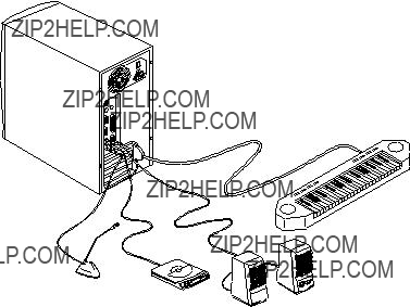
on the rear panel. See the following figure:

Figure 4-21 Connecting USB Devices

Most USB devices have a built-in USB port which allows you to daisy-chain other devices.

4-20 AcerPower 6000 User???s Guide

Index

A

B

C

D

E

F

H

I

Index 1

L

M

N

O

P

R

S

2 AcerPower 6000 User???s Guide

Index 3

Index 5