Aspire 4730Z/4730ZG/4330 Series Service Guide
Service guide files and updates are available on the ACER/CSD web; for more information, please refer to http://csd.acer.com.tw
PRINTED IN TAIWAN
Aspire 4730Z/4730ZG/4330 Series Service Guide
Service guide files and updates are available on the ACER/CSD web; for more information, please refer to http://csd.acer.com.tw
PRINTED IN TAIWAN

Revision History
Please refer to the table below for the updates made on Aspire 4720Z/4730ZG/4330 Series service guide.
II

Copyright
Copyright ?? 2008 by Acer Incorporated. All rights reserved. No part of this publication may be reproduced, transmitted, transcribed, stored in a retrieval system, or translated into any language or computer language, in any form or by any means, electronic, mechanical, magnetic, optical, chemical, manual or otherwise, without the prior written permission of Acer Incorporated.
Disclaimer
The information in this guide is subject to change without notice.
Acer Incorporated makes no representations or warranties, either expressed or implied, with respect to the contents hereof and specifically disclaims any warranties of merchantability or fitness for any particular purpose. Any Acer Incorporated software described in this manual is sold or licensed as is. Should the programs prove defective following their purchase, the buyer (and not Acer Incorporated, its distributor, or its dealer) assumes the entire cost of all necessary servicing, repair, and any incidental or consequential damages resulting from any defect in the software.
Acer is a registered trademark of Acer Corporation. Intel is a registered trademark of Intel Corporation.
Pentium and Pentium II/III are trademarks of Intel Corporation.
Other brand and product names are trademarks and/or registered trademarks of their respective holders.
III

Conventions
The following conventions are used in this manual:
IV

Preface
Before using this information and the product it supports, please read the following general information.
1.This Service Guide provides you with all technical information relating to the BASIC CONFIGURATION decided for Acer's global product offering. To better fit local market requirements and enhance product competitiveness, your regional office MAY have decided to extend the functionality of a machine (e.g.
2.Please note WHEN ORDERING FRU PARTS, that you should check the most
V

VI

Table of Contents
Features . . . . . . . . . . . . . . . . . . . . . . . . . . . . . . . . . . . . . . . . . . . . . . . . . . . . . . . . . . . .1 System Block Diagram . . . . . . . . . . . . . . . . . . . . . . . . . . . . . . . . . . . . . . . . . . . . . . . . .4 Your Acer Notebook tour . . . . . . . . . . . . . . . . . . . . . . . . . . . . . . . . . . . . . . . . . . . . . . .5 Front View . . . . . . . . . . . . . . . . . . . . . . . . . . . . . . . . . . . . . . . . . . . . . . . . . . . . . . .5 Closed Front View . . . . . . . . . . . . . . . . . . . . . . . . . . . . . . . . . . . . . . . . . . . . . . . . .6 Left View . . . . . . . . . . . . . . . . . . . . . . . . . . . . . . . . . . . . . . . . . . . . . . . . . . . . . . . .7 Right View . . . . . . . . . . . . . . . . . . . . . . . . . . . . . . . . . . . . . . . . . . . . . . . . . . . . . . .8 Rear View . . . . . . . . . . . . . . . . . . . . . . . . . . . . . . . . . . . . . . . . . . . . . . . . . . . . . . .8 Bottom View . . . . . . . . . . . . . . . . . . . . . . . . . . . . . . . . . . . . . . . . . . . . . . . . . . . . .9 Indicators . . . . . . . . . . . . . . . . . . . . . . . . . . . . . . . . . . . . . . . . . . . . . . . . . . . . . .10
Using the System Utilities . . . . . . . . . . . . . . . . . . . . . . . . . . . . . . . . . . . . . . . . . . . . . .16 Acer GridVista
VII

VIII

Table of Contents
No Display Issue . . . . . . . . . . . . . . . . . . . . . . . . . . . . . . . . . . . . . . . . . . . . . . . .131 Random Loss of BIOS Settings . . . . . . . . . . . . . . . . . . . . . . . . . . . . . . . . . . . .132 LCD Failure . . . . . . . . . . . . . . . . . . . . . . . . . . . . . . . . . . . . . . . . . . . . . . . . . . . .133
IX

Table of Contents
X
Chapter 1
System Specifications
Features
Below is a brief summary of the computer???s many feature:
NOTE: Items marked with * denote only selected models.
Operating System
???Genuine Windows Vista???
Platform
???Intel?? Pentium??
???Intel?? Celeron??
???Intel?? Celeron?? processor*
???Mobile Intel?? PM45 Express Chipset*
???Mobile Intel?? GL40 Express Chipset*
???Acer InviLink??? Nplify???
???Acer InviLink??? 802.11b/g*
System Memory
???
???Up to 2 GB of DDR2 667 MHz memory, upgradeable to 4 GB using two soDIMM modules*
Display and graphics
???14.1" WXGA 1280 x 800
???Mobile Intel?? GL40 Express Chipset*
???ATI Mobility Radeon??? HD 3470*
Storage subsystem
???2.5" hard disk drive
???Optical drive options:
???
???
???
Audio
???Two
???
???
???

Communication
???Acer Video Conference, featuring:
???Integrated Acer Crystal Eye webcam
???Optional Acer Xpress VoIP phone
???WLAN:
???Acer InviLink??? Nplify???
???Acer InviLink??? 802.11b/g*
???WPAN: Bluetooth?? 2.0+EDR
???LAN: Gigabit Ethernet,
???Modem: 56K ITU V.92
Privacy control
???BIOS user, supervisor, HDD passwords
???Kensington lock slot
Dimensions and Weight
???340.4 (W) x 247 (D) x 22.9/42.3 (H) mm (13.4 x 9.7 x 0.9/1.6 inches)
???2.4 kg (5.29 Ibs)
Power subsystem
???ACPI 3.0
???48.8 W 4400 mAh
???
???
???Energy Star 4.0
Special keys and controls
???
???Touchpad pointing device
???Empowering Key
???
I/O interface
???ExpressCard???/54 slot
???
???Two USB 2.0 ports
???External display (VGA) port
???
???
???
???Ethernet

?????? Modem
??????
Environment
???Temperature:
???Operating: 5 ??C to 35 ??C
???
???Humidity
???Operating: 20% to 80%
???
NOTE: Items marked with * denote only selected models. The specifications listed above are for reference only. The exact configuration of your PC depends on the model purchased.

System Block Diagram

Your Acer Notebook tour
After knowing your computer features, let us show you around your new computer.
Front View

Closed Front View

Left View

Right View
Rear View

Bottom View

Indicators
The computer has several
The front panel indicators are visible even when the computer cover is closed.
NOTE: 1. Charging: The battery light shows amber when the battery is charging. 2. Fully charged: The light shows green when in AC mode.
Located beside the keyboard are application buttons. These buttons are called
The mail and Web browser buttons are
Touchpad Basics (with fingerprint reader)
The following items show you how to use the touchpad with Acer
???Move your finger across the touchpad (2) to move the cursor.
???Press the left (1) and right (4) buttons located beneath the touchpad to perform selection and execution functions. These two buttons are similar to the left and right buttons on a mouse. Tapping on the touchpad is the same as clicking the left button.
???Use Acer
NOTE: When using the touchpad, keep it - and your fingers - dry and clean. The touchpad is sensitive to finger movement; hence, the lighter the touch, the better the response. Tapping too hard will not increase the touchpad???s responsiveness.

Using the Keyboard
The keyboard has
Lock Keys and embedded numeric keypad
The keyboard has three lock keys which you can toggle on and off.
The embedded numeric keypad functions like a desktop numeric keypad. It is indicated by small characters located on the upper right corner of the keycaps. To simplify the keyboard legend,

Windows Keys
The keyboard has two keys that perform
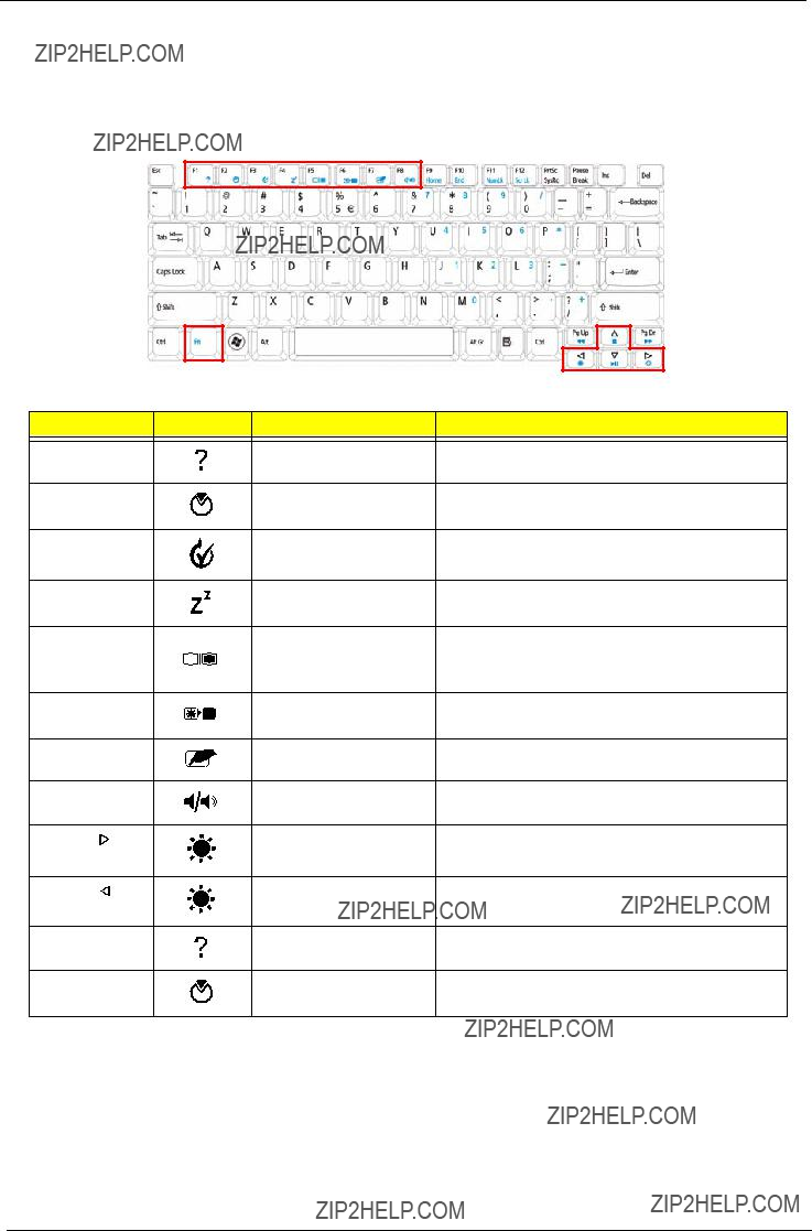
Hot Keys
The computer employs hotkeys or key combinations to access most of the computer???s controls like screen brightness, volume output and the BIOS utility.
To activate hot keys, press and hold the <Fn> key before pressing the other key in the hotkey combination.
Special Key
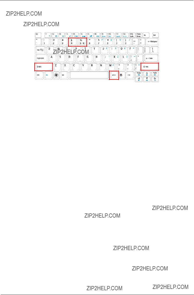
You can locate the Euro symbol and the US dollar sign at the
The Euro symbol
1.Open a text editor or word processor.
2.Hold <Alt Gr> and then press the <5> key at the
NOTE: Note: Some fonts and software do not support the Euro symbol. Please refer to www.microsoft.com/ typography/faq/faq12.htm for more information.
The US dollar sign
1.Open a text editor or word processor.
2.Hold <Shift> and then press the <4> key at the

Using the System Utilities
Acer
Acer
For more information refer to the Acer
Acer GridVista
NOTE: This feature is only available on certain models.
To enable the dual monitor feature of the notebook, first ensure that the second monitor is connected, then select Start, Control Panel, Display and click on Settings. Select the secondary monitor (2) icon in the display box and then click the check box Extend my windows desktop onto this monitor. Finally, click Apply to confirm the new settings and click OK to complete the process.
Acer GridVista is a handy utility that offers four
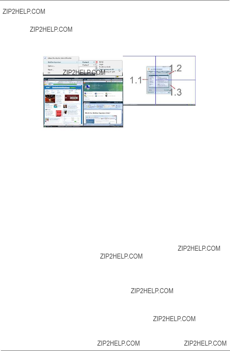
Double (vertical), Triple (primary at left), Triple (primary at right), or Quad Acer Gridvista is
Acer Gridvista is
1.Run Acer GridVista and select your preferred screen configuration for each display from the task bar.
2.Drag and drop each window into the appropriate grid.
3.Enjoy the convenience of a
NOTE: Please ensure that the resolution setting of the second monitor is set to the manufacturer's recommended value.

Hardware Specifications and Configurations
Processor
???Throttling 50%: On= 85??C; OFF=78??C
???OS shut down at 90??C; H/W shut down at 96??C
CPU Fan True Value Table UMA SKU
???Throttling 50%: On= 85??C; OFF=78??C
???OS shut down at 90??C; H/W shut down at 96??C

BIOS

Memory Combinations
NOTE: Above table lists some system memory configurations. You may combine DIMMs with various capacities to form other combinations. On above table, the configuration of slot 1 and slot 2 could be reversed.
Graphics Controller
Wireless Module 802.11b/g


USB Interface

LCD Inverter

Chapter 2
System Utilities
BIOS Setup Utility
The BIOS Setup Utility is a hardware configuration program built into your computer???s BIOS (Basic Input/ Output System).
Your computer is already properly configured and optimized, and you do not need to run this utility. However, if you encounter configuration problems, you may need to run Setup. Please also refer to Chapter 4 Troubleshooting when problem arises.
To activate the BIOS Utility, press F2 during POST (when ???Press <F2> to enter Setup??? message is prompted on the bottom of screen).
Press F2 to enter setup. The default parameter of F12 Boot Menu is set to ???disabled???. If you want to change boot device without entering BIOS Setup Utility, please set the parameter to ???enabled???.
Press <F12> during POST to enter
Navigating the BIOS Utility
There are six menu options: Information, Main, Advanced, Security, Boot, and Exit.
Follow these instructions:
???To choose a menu, use the left and right arrow keys.
???To choose an item, use the up and down arrow keys.
???To change the value of a parameter, press F5 or F6.
???A plus sign (+) indicates the item has
???Press Esc while you are in any of the menu options to go to the Exit menu.
???In any menu, you can load default settings by pressing F9. You can also press F10 to save any changes made and exit the BIOS Setup Utility.
NOTE: You can change the value of a parameter if it is enclosed in square brackets. Navigation keys for a particular menu are shown on the bottom of the screen. Help for parameters are found in the Item Specific Help part of the screen. Read this carefully when making changes to parameter values. Please note that system information is subject to different models.

Information
The Information screen displays a summary of your computer hardware information.
NOTE: The system information is subject to different models.

Main
The Main screen allows the user to set the system time and date as well as enable and disable boot option and recovery.
NOTE: The screen above is for your reference only. Actual values may differ.
The table below describes the parameters in this screen. Settings in boldface are the default and suggested parameter settings.
NOTE: The

Security
The Security screen contains parameters that help safeguard and protect your computer from unauthorized use.
The table below describes the parameters in this screen. Settings in boldface are the default and suggested parameter settings.
NOTE: When you are prompted to enter a password, you have three tries before the system halts. Don???t forget your password. If you forget your password, you may have to return your notebook computer to your dealer to reset it.
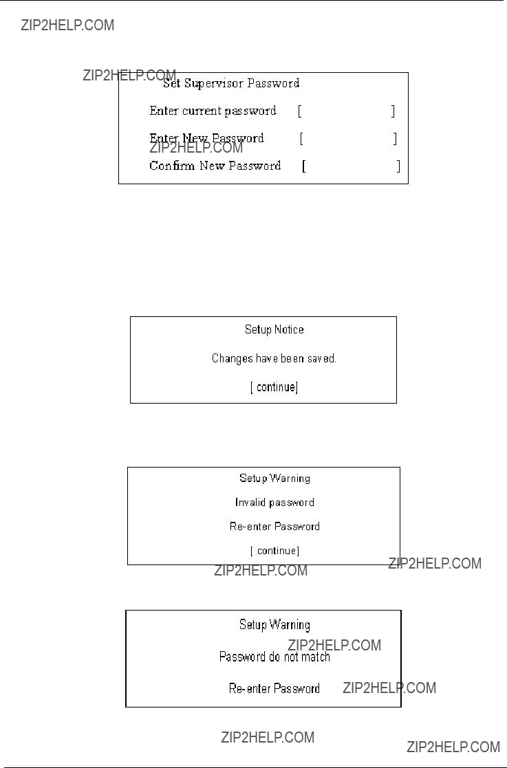
Setting a Password
Follow these steps as you set the user or the supervisor password:
1.Use the ??? and ??? keys to highlight the Set Supervisor Password parameter and press the Enter key. The Set Supervisor Password box appears:
2.Type a password in the ???Enter New Password??? field. The password length can not exceeds 8 alphanumeric characters
IMPORTANT:Be very careful when typing your password because the characters do not appear on the screen.
3.Press Enter. After setting the password, the computer sets the User Password parameter to ???Set???.
4.If desired, you can opt to enable the Password on boot parameter.
5.When you are done, press F10 to save the changes and exit the BIOS Setup Utility.
Removing a Password
Follow these steps:
1.Use the ??? and ??? keys to highlight the Set Supervisor Password parameter and press the Enter key. The Set Password box appears:
2.Type the current password in the Enter Current Password field and press Enter.
3.Press Enter twice without typing anything in the Enter New Password and Confirm New Password fields. The computer then sets the Supervisor Password parameter to ???Clear???.
4.When you have changed the settings, press u to save the changes and exit the BIOS Setup Utility.
Changing a Password
1.Use the ??? and ??? keys to highlight the Set Supervisor Password parameter and press the Enter key. The Set Password box appears.
2.Type the current password in the Enter Current Password field and press Enter.
3.Type a password in the Enter New Password field. Retype the password in the Confirm New Password field.
4.Press Enter. After setting the password, the computer sets the User Password parameter to ???Set???.
5.If desired, you can enable the Password on boot parameter.
6.When you are done, press F10 to save the changes and exit the BIOS Setup Utility.
If the verification is OK, the screen will display as following.
The password setting is complete after the user presses Enter.
If the current password entered does not match the actual current password, the screen will show you the Setup Warning.
If the new password and confirm new password strings do not match, the screen will display the following message.

Boot
This menu allows the user to decide the order of boot devices to load the operating system. Bootable devices includes the USB diskette drives, the onboard hard disk drive and the DVD drive in the module bay.

Exit
The Exit screen allows you to save or discard any changes you made and quit the BIOS Utility.
The table below describes the parameters in this screen.

BIOS Flash Utility
The BIOS flash memory update is required for the following conditions:
???New versions of system programs
???New features or options
???Restore a BIOS when it becomes corrupted. Use the Phlash utility to update the system BIOS flash ROM.
NOTE: Create a Crisis Recovery Media (such as USB HDD) before you use the Phlash utility.
NOTE: Do not install
NOTE: Please use the AC adaptor power supply when you run the Phlash utility. If the battery pack does not contain enough power to finish BIOS flash, the system will not boot as the BIOS is not loaded.
Perform the following steps to use the Flash Utility:
1.Press F2 during boot to enter the Setup Menu.
2.Select Boot Menu to modify the boot priority order, for example, if using USB HDD to Update BIOS, move USB HDD to position 1.
3.Execute the IFLASH.BAT batch file to update BIOS (Read xxxxx.fd to Memory).

4. In flash BIOS, the message Please do not remove AC Power Source displays.
NOTE: If the AC power is not connected, the following message displays.
Plug in the AC power to continue.
5.Flash is complete when the following message displays.
6.Shutdown or reboot base on iflash.bat command.

Remove HDD/BIOS Utility
This section provide you with removing HDD/BIOS method:
Remove HDD Password:
???If you key in wrong HDD password three times, Hdd password error code displays. See the image below.
To reset the HDD password, run HDD_PW.EXE as follows:
1.Key in hdd_pw 15494 0
2.Press 2.
3.Select one
4.Reboot system and key in the selected string (0KJFN42 or UVEIQ96) on the HDD User Password screen.

Remove BIOS Password:
If you key in the wrong Supervisor Password three times, System Disabled displays on the screen. See the image below.
To reset the BIOS password, run BIOS_PW.EXE as follows:
1.Key in bios_pw 14452 0
2.Select one string from the list.

3.Reboot the system and key in the selected string (qjjg9vy, 07yqmjd etc.) for the BIOS user password.
Removing BIOS Passwords:
To clear the password, perform the following steps:
1.From a DOS prompt, Execute clnpwd.exe
2.Press 1 or 2 to clean the desired password shown on the screen.
The onscreen message determines whether the function is successful or not.

Chapter 3
Machine Disassembly and Replacement
This chapter contains
Disassembly Requirements
To disassemble the computer, you need the following tools:
???Wrist grounding strap and conductive mat for preventing electrostatic discharge
???Flat screwdriver
???Philips screwdriver
???Plastic flat screwdriver
???Plastic tweezers
NOTE: The screws for the different components vary in size. During the disassembly process, group the screws with the corresponding components to avoid mismatch when putting back the components.
IMPORTANT:Various images depict the use of a regular metal screwdriver, however, a plastic screwdriver is advised when disassembling parts near or around the motherboard and to prevent scratching of the computer surface.

General Information
Before proceeding with the disassembly procedure, make sure that you do the following:
1.Turn off the power to the system and all peripherals.
2.Unplug the AC adapter and all power and signal cables from the system.
3.Place the system on a flat, stable surface.
4.Remove the battery pack.
Disassembly Process
The disassembly process is divided into the following stages:
???External module disassembly
???Main unit disassembly
???LCD module disassembly
The flowcharts provided in the succeeding disassembly sections illustrate the entire disassembly sequence. Observe the order of the sequence to avoid damage to any of the hardware components. For example, if you want to remove the main board, you must first remove the keyboard, then disassemble the inside assembly frame in that order.
Main Screw List

External Module Disassembly Process
External Modules Disassembly Flowchart
The flowchart below gives you a graphic representation on the entire disassembly sequence and instructs you on the components that need to be removed during servicing. For example, if you want to remove the main board, you must first remove the keyboard, then disassemble the inside assembly frame in that order.
Turn off system and peripherals power
Disconnect power and signal cables from system
Remove Battery
Remove
Remove
Express Dummy
SD Dummy Card
Card
Remove
Lower Covers

Removing the Battery Pack
1.Turn computer over.
2.Slide the battery lock/unlock latch to the unlock position.
3.Slide and hold the battery release latch to the release position (1), then slide out the battery pack from the main unit (2).
2
1

Removing the SD dummy card
1. Push the SD dummy card all the way in to eject it.
2. Pull it out from the slot.
Removing the ExpressCard dummy card
1. Push the ExpressCard dummy card all the way in to eject it.
2. Pull it out from the slot.

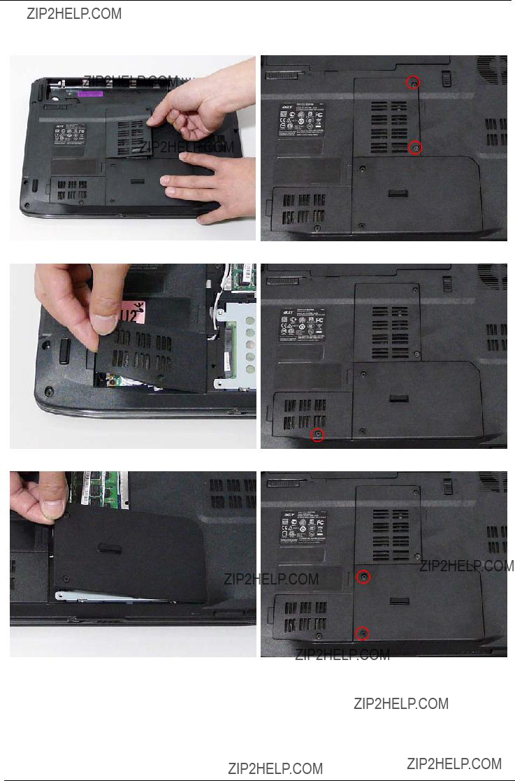
Removing the Lower Covers
1.See ???Removing the Battery Pack??? on page 44.
2.See ???Removing the SD dummy card??? on page 45.
3.See ???Removing the ExpressCard dummy card??? on page 46.
4.Remove the three screws from the memory and WLAN bays and loosen the two captive screws on the HDD cover.
5. Carefully open the memory cover.

6. Remove the HDD cover as shown.
7. Remove the WLAN cover as shown.

Removing the DIMM Modules
1.See ???Removing the Battery Pack??? on page 44.
2.Remove the Memory Module cover See ???Removing the Lower Covers??? on page 47.
3.Push out the release latches on both sides of the DIMM socket to release the DIMM module.
4. Remove the DIMM module.
5. Repeat steps for the second DIMM module if present.

Removing the WLAN Module
1.See ???Removing the Battery Pack??? on page 44.
2.Remove the WLAN cover. See ???Removing the Lower Covers??? on page 47.
3.Disconnect the antenna cables from the WLAN board.
4. Move the antenna away and remove the two screws on the WLAN board to release the WLAN board.
5. Detach the WLAN board from the WLAN socket.
NOTE: When attaching the antenna back to the WLAN board, make sure the cables are sitting in the housing to prevent damage.

Removing the Hard Disk Drive Module
1.See ???Removing the Battery Pack??? on page 44.
2.Remove the HDD cover, See ???Removing the Lower Covers??? on page 47.
3.Use the
NOTE: To prevent damage to device, avoid pressing down on it or placing heavy objects on top of it.

4. Remove the four screws securing the hard disk to the carrier.

5. Remove the HDD from the carrier.

Removing the Optical Drive Module
1.See ???Removing the Battery Pack??? on page 44.
2.Remove the Memory cover. See ???Removing the Lower Covers??? on page 47.
3.Remove the screw securing the ODD module.
4. Carefully insert a screw driver to release the locking latch.
NOTE: A plastic screw driver is recommended to prevent scratching the surface of the computer.

5. Pull the optical drive module out from the chassis.
6.Remove the three screws securing the ODD bracket and remove the ODD bracket from the optical disk drive module.
7. Insert a pin in the eject hole of the ODD to eject the ODD tray.
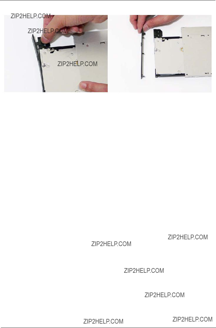
8. Press down on the locking catch to release the ODD cover and remove.

Main Unit Disassembly Process
Main Unit Disassembly Flowchart
Remove External Modules before proceeding
Screw List

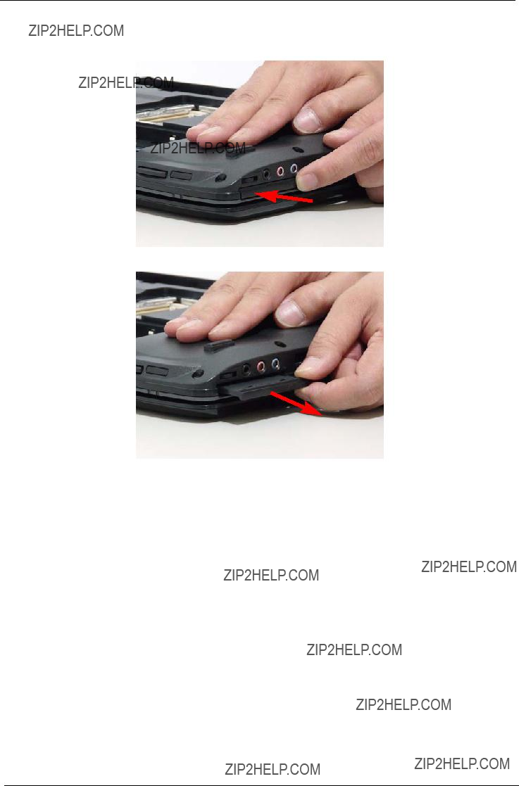
Removing the Switch Cover
CAUTION: Using tools to remove the Switch Cover may cause damage to the outer casing. It is recommended that you only use your fingers to remove the Switch Cover.
1.See ???Removing the Battery Pack??? on page 44.
2.Locate and remove the two securing screws as shown.
3.Turn the computer over and open the LCD module to expose the Switch Cover.
4.Lift the Switch Cover as shown, and move from right to left side.

5. Turn the Switch Cover over to expose the FFC cable and detach it using the tweezers.
6. Lift the Switch Cover clear of the chassis.
Removing the Keyboard
1.See ???Removing the Battery Pack??? on page 44.
2.Using a plastic pry, push in the two securing latches and slide the pry under the keyboard.
3. Once both latches are released, lift the keyboard away from the chassis as shown.
4. Turn the keyboard over on the Touch Pad area to expose the FFC cable.

5. Using a pry, pull both sides of the retainer to disconnect the FFC cable from the mainboard.

Removing the Antenna
1. Remove the Antenna Cables from the securing pins as shown.
2. Turn the computer over. Remove the adhesive strips holding the antenna cables.
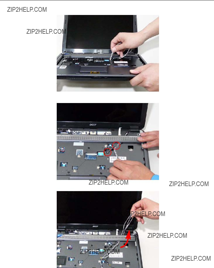
3. Feed the antenna cables from the underside of the computer.
4. Remove the Antenna Cables from the securing pins as shown.
5. Pull the cables through the speaker panel as shown.

6. Fully remove the antenna cables and move them out of the way to prevent damage.

Removing the LCD Module
1.See ???Removing the Battery Pack??? on page 44.
2.See ???Removing the Lower Covers??? on page 47.
3.See ???Removing the WLAN Module??? on page 50.
4.See ???Removing the Keyboard??? on page 61.
5.See ???Removing the Antenna??? on page 63.
6.Remove the two securing screws from the bottom of the chassis.
7. Turn the computer over. Disconnect the three LCD interface cables from the chassis.

8. Remove the four securing screws (two each side) from the LCD module.
9. Carefully remove the LCD module from the chassis.

Removing the Upper Cover
1.See ???Removing the Battery Pack??? on page 44.
2.See ???Removing the SD dummy card??? on page 45.
3.See ???Removing the ExpressCard dummy card??? on page 46.
4.See ???Removing the Lower Covers??? on page 47.
5.See ???Removing the DIMM Modules??? on page 49.
6.See ???Removing the WLAN Module??? on page 50.
7.See ???Removing the Hard Disk Drive Module??? on page 52.
8.See ???Removing the Optical Drive Module??? on page 55.
9.See ???Removing the Switch Cover??? on page 59.
10.See ???Removing the Keyboard??? on page 61.
11.See ???Removing the LCD Module??? on page 66.
12.Turn the computer over. Remove the eight screws on the bottom panel.

13. Turn the computer over. Remove the seven screws on the top panel.
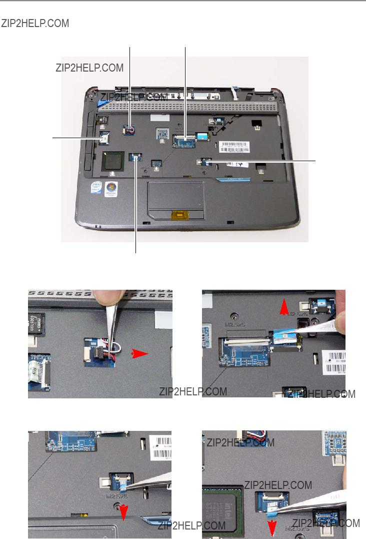
14. Disconnect the five cables from the mainboard as shown.
AB
E
C
Release the securing latches and disconnect C as shown.
Release the securing latches and disconnect D as shown.
Release the securing latches and disconnect E as shown.
15. Remove the upper cover by lifting upward from the chassis, rear edge first.
16. Turn the upper cover over. The upper cover appears as follows.
NOTE: Avoid pulling on the cables directly to prevent damage to the connectors.
NOTE: Use the

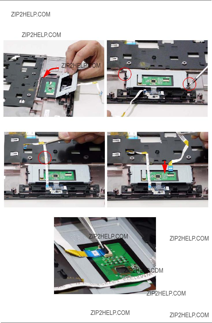
Removing the Touch Pad Bracket
1.See ???Removing the Upper Cover??? on page 68.
2.Disconnect the Touch Pad cable from the Touch Pad board.
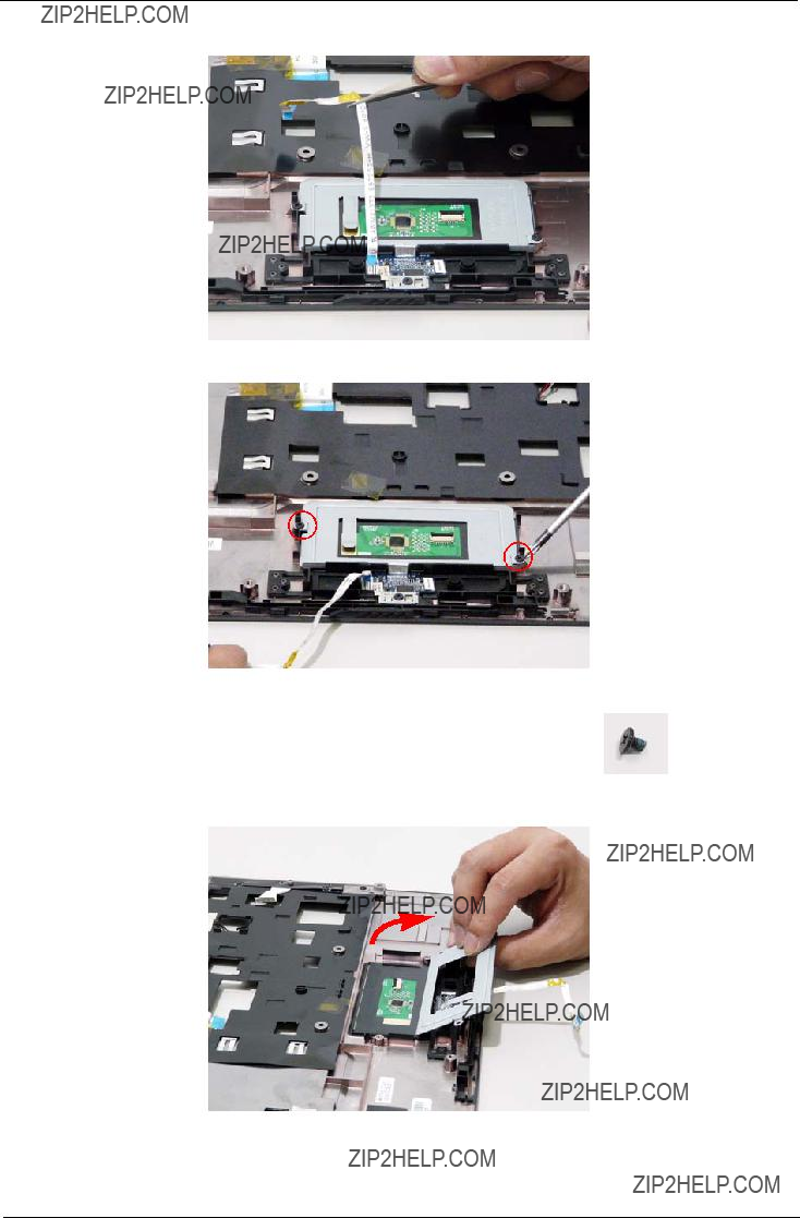
3. Move the Finger Print Reader FFC cable out of the way to prevent damage.
4. Remove the two securing screws from the Touch Pad bracket.
5. Remove the Touch Pad bracket.
IMPORTANT:The Touch Pad cannot be removed individually. To replace the Touch Pad, replace the entire Upper Cover.

Removing the Finger Print Reader
1.See ???Removing the Upper Cover??? on page 68.
2.Remove the securing screw from the Finger Print Reader board.
3. Remove the Finger Print Reader board from the Upper Cover.
Removing the Launch Board
1.See ???Removing the Upper Cover??? on page 68.
2.Remove the two screws from the Launch Board.
3. Remove the Launch Board from the Upper Cover.

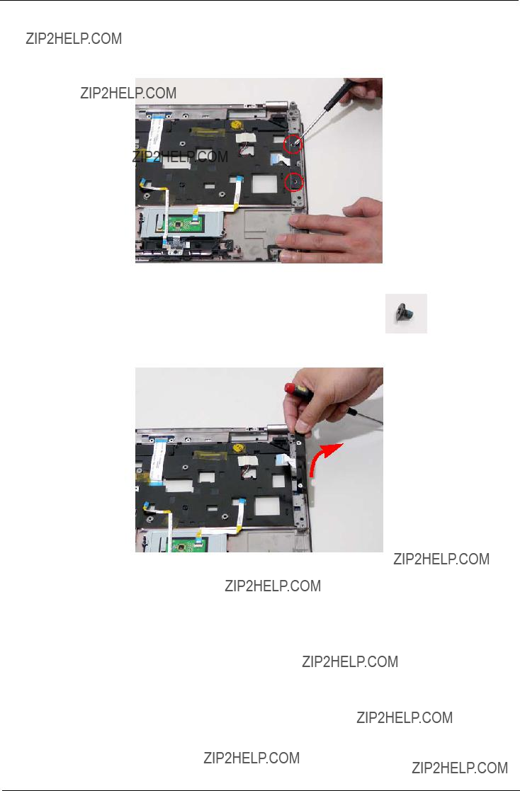
Removing the Speaker Module
1.See ???Removing the Upper Cover??? on page 68.
2.Remove the adhesive tape from the speaker cable.
3. Remove the four screws holding the Speaker Module in place.
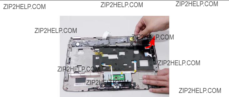
4. Remove the Speaker Module from the upper cover.

Removing the Switch Board
1.See ???Removing the Upper Cover??? on page 68.
2.Ensure the Switch Board cable is free from any obstructions.
3. Turn the Upper Cover. Remove the Switch Board as shown.

Removing the Touch Pad Board
IMPORTANT:The Touch Pad board is integrated into the design of the Upper Cover. To replace the Touch Pad board, remove all components from the Upper Cover and install an entirely new Upper Cover.
IMPORTANT:The MOSFET pad is attached to the Upper Cover and is reusable. If the replacement Upper Cover does not have a MOSFET pad (see highlighted area below), remove the MOSFET pad from the replaced Upper Cover and stick it to the new Upper Cover.
1.See ???Removing the Battery Pack??? on page 44.
2.See ???Removing the SD dummy card??? on page 45.
3.See ???Removing the ExpressCard dummy card??? on page 46.
4.See ???Removing the Lower Covers??? on page 47.
5.See ???Removing the DIMM Modules??? on page 49.
6.See ???Removing the WLAN Module??? on page 50.
7.See ???Removing the Hard Disk Drive Module??? on page 52.
8.See ???Removing the Optical Drive Module??? on page 55.
9.See ???Removing the Keyboard??? on page 61.
10.See ???Removing the LCD Module??? on page 66.
11.See ???Removing the Upper Cover??? on page 68.
12.See ???Removing the Touch Pad Bracket??? on page 72.
13.See ???Removing the Finger Print Reader??? on page 74.
14.See ???Removing the Launch Board??? on page 75.

Removing the I/O Board
1.See ???Removing the Upper Cover??? on page 68.
2.Remove the securing screw from the I/O Board.
3. Lift the I/O Board clear of the Lower cover.
4. Disconnect the I/O Board cable and remove the board.

Removing the Bluetooth module
1.See ???Removing the Upper Cover??? on page 68.
2.Remove the securing screw from the Bluetooth module.
3. Lift the Bluetooth module away from the mainboard and disconnect the mainboard cable.

4. Disconnect the cable from the mainboard.

Removing the Modem Module
1.See ???Removing the Upper Cover??? on page 68.
2.Remove the adhesive strip securing the Modem cable to the Lower Cover.
3. Remove the

4. Disconnect the Modem cable from the Modem module.
5. Remove the two screws securing the Modem module.
6. Remove the Modem module from the Lower Cover.

Removing the Main Board
1.See ???Removing the Upper Cover??? on page 68.
2.Disconnect the power jack from the power port on the Lower Cover.
3. Lift the cabling clear of the securing pins and ensure it is free of obstruction.

4. Remove the securing screw from the Mainboard.
5. Remove the main board, rightside first, as shown.
6. Release the securing latches and remove the Switch Cover FFC.

7. Turn the Mainboard over. Disconnect the I/O Cable from the Mainboard.
8. Disconnect the DC IN Cable from the Mainboard.

Removing the Thermal Module
1.See ???Removing the Main Board??? on page 86.
2.Remove the four securing screws from the Thermal Module.
3. Lift the Thermal Module clear of the Mainboard.

Removing the CPU
1.See ???Removing the Main Board??? on page 86.
2.See ???Removing the Thermal Module??? on page 89.
3.Using a flat screwdriver, turn the CPU socket latch
k
4. Lift the CPU clear of the Mainboard.
Removing the CPU Fan
1.See ???Removing the Main Board??? on page 86.
2.Disconnect the Fan cable from the Mainboard.
3. Remove the three securing screws from the Fan module.

4. Lift the Fan module clear of the Mainboard.

Removing the HDMI Module
1.See ???Removing the Main Board??? on page 86.
2.Remove the two securing screws from the HDMI Module.
3. Remove the HDMI Module as shown.

LCD Module Disassembly Process
LCD Module Disassembly Flowchart
Remove LCD Panel from Main Unit before proceeding

Removing the LCD Bezel
1.See ???Removing the LCD Module??? on page 66.
2.Remove the two upper and two lower bezel screw caps.
3. Remove the four securing screws from the LCD module.

4. Starting from the inside edges of the bezel, pry the bezel upwards and away from the panel. Move along the sides until all sides of the bezel are removed.
NOTE: If necessary, use a plastic pry to lift up the outside edges of the bezel.
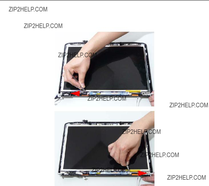
Removing the Inverter Board
1.See ???Removing the LCD Bezel??? on page 95.
2.Disconnect the left and right Inverter board cables as shown.

3.Remove the securing screw from the Inverter board.
4. Lift the Inverter board clear of the LCD Module.

Removing the Camera Module
1.See ???Removing the LCD Bezel??? on page 95.
2.Disconnect the Camera Module cable as shown.
3. Remove the two securing screws from the Camera Module.

4. Lift the Camera Module clear of the LCD Module.
Removing the LCD Panel
1.See ???Removing the LCD Bezel??? on page 95.
2.Remove the two securing screws from the LCD Module.
IMPORTANT:The leftside screw holds the ground connector in place. Ensure that the ground is replaced during reassembly.
3. Lift the LCD Panel clear of the LCD Module.

Removing the LCD Brackets and FPC Cable
1.See ???Removing the LCD Panel??? on page 101.
2.Turn the LCD panel over to expose the rear. Disconnect the cable from the LCD Panel using the tab provided.
3. Grip the FPC cable and lift upward to detach the adhesive pads.
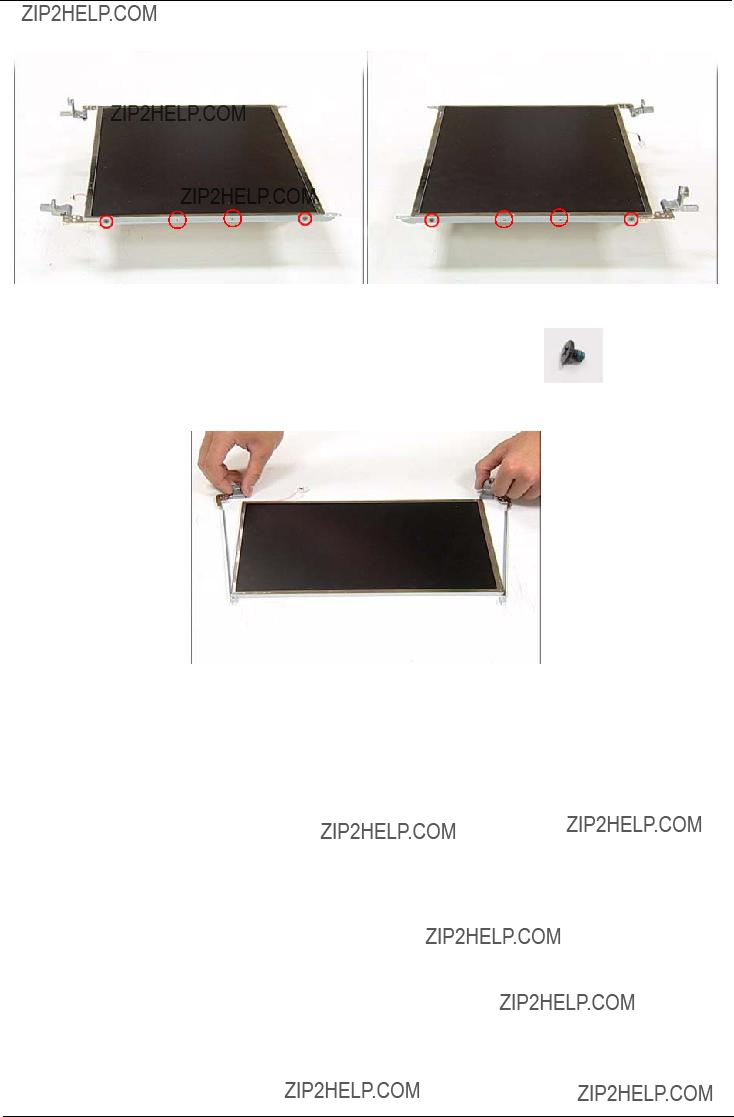
4. Remove the eight securing screws (four on each side) from the LCD Panel brackets.
5. Remove the LCD brackets by pulling away from the LCD Panel as shown.

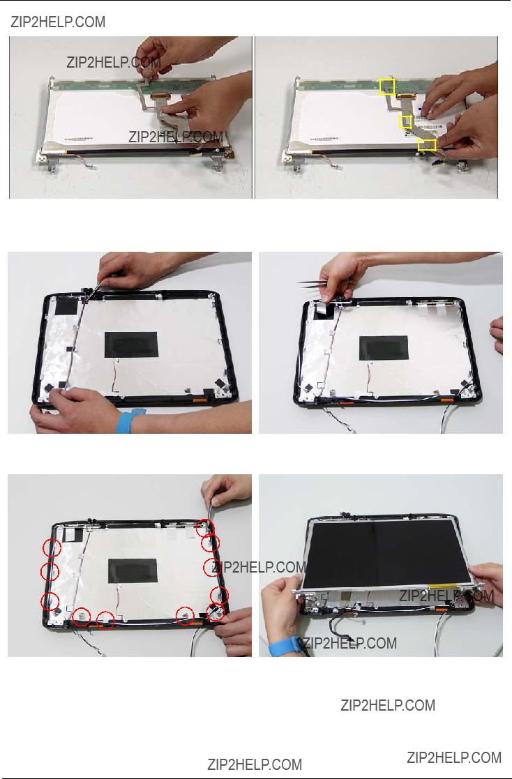
Removing the Antennas
1.See ???Removing the LCD Panel??? on page 101.
2.Remove the strips holding the antenna cables in place. Ensure the cables are free from obstructions.
3. Remove the tab securing the left and right antennas to the LCD module.
4. Remove the antenna cables and assembly from the LCD module.

Removing the MIC Module
1.See ???Removing the Antennas??? on page 104.
2.Remove the strips holding the MIC Module cable in place. Ensure the cable is free from obstructions.
3. Remove the MIC cable and Module from the LCD module.

LCD Module Reassembly Procedure
Replacing the LCD Panel
1. Align the LCD brackets with the eight screw holes (four on each side) on the LCD Panel as shown.
2. Secure the LCD brackets to the LCD panel.
3. Turn the panel over. Insert the LCD Panel cable into the LCD Panel as shown.
4. Align the LCD Panel cable as shown and press down to engage the adhesive pads.
5.Replace the MIC cable under the mylar tab strips, and replace the MIC as shown. Secure the cable by pressing down on the strips.
6.Replace the antenna cable as shown. Ensure that the cable is inserted under each tab strip.
7. Secure the cable by pressing down on the securing 8. Place the LCD Panel in the back cover. strip.

9.Secure the LCD module with the two securing screws.
IMPORTANT:Ensure that the ground connector is secured in place with the leftside panel screw.
11. Replace the two securing screws.
10.Insert the Camera Module (adhesive side down), and secure by pressing down to insure cohesion.
12. Connect the Camera Module cable.
13. Replace the Inverter board and secure with the single screw.

14. Connect the left and right Inverter cables.
Replacing the LCD Bezel
1.Locate the bezel correctly and press down the edges until there are no gaps between the bezel and the LCD Module,
2. Replace the four screws and the rubber screw caps provided.

Main Module Reassembly Procedure
Replacing the CPU
1.Carefully turn the mainboard upside down (CPU side up), and insert the CPU into the CPU bracket as shown.
2.Using a plastic screw driver, lock the CPU in the socket as shown.
Replacing the Thermal Module
1. Align and place the Thermal Module in the mounting as shown.
2. Replace the four securing screws to secure the Thermal Module.
Replacing the CPU Fan Module
3. Connect the Fan cable to the Mainboard.
Replacing the HDMI Module
1.Insert the HDMI Module as shown, and press down to locate in place.
2. Replace the 2 screws to secure.

Replacing the Mainboard
1. Turn the Mainboard over. Connect the DC IN Cable 2. Connect the I/O Cable to the Mainboard. to the Mainboard.
3. Replace the Switch Cover FFC and lock the securing latches in place.
4.Ensure that the Mainboard is face up (the Heatsink and CPU are not visible). Place the Mainboard in the chassis, rear edge first, and press down to install. Replace the two securing screws as shown.
NOTE: Make sure the I/O ports are positioned correctly through the lower cover, and the screw sockets are visible through the mainboard.

7. Connect the power jack to the power port on the Lower Cover.

Replacing the I/O Board
3. Replace the single securing screw.
Replacing the Bluetooth Board
1.Connect one end of the Bluetooth cable to the mainboard as shown.
2.Connect the other end of the Bluetooth cable to the Bluetooth Module as shown.

3. Locate the Bluetooth Module and replace the single securing screw.
Replacing the Modem Module
1.Replace the Modem Module and secure the two screws as shown.
2.Connect the Modem cable to the Modem Module as shown.
3.Connect the
4.Replace the adhesive strips to secure the Modem cable to the Lower Cover.

Replacing the Finger Print Reader
1. Replace the Finger Print Reader board in the upper cover.
2. Replace the securing screw.
3.Secure the FFC to the upper cover by using the adhesive tape.
Replacing the Touch Pad Bracket
IMPORTANT:The Touch Pad cannot be removed individually. To replace the Touch Pad, replace the entire Upper Cover.
3.Replace the Finger Print reader FFC and secure with the adhesive strips.
4.Replace the Touch Pad FFC and secure with the adhesive strips.
5. Connect the Touch Pad cable to the Touch Pad board.

Replacing the Launch Board
1. Replace the Launch Board on the upper cover.
Replacing the Switch Board
1.Turn the Upper Cover over and insert the FFC through the cover as shown.
2. Replace the two securing screws.
2.Flip the Upper Cover over and replace the Switch Board as shown.

Replacing the Antenna Cables
Ensure that the three Antenna cables pass through the Mainboard and are accessible from the underside of lower cover.
1.Insert the Antenna Cables through the Upper Cover. Make sure they are accessible from the underside.
2. Secure the cables in place as shown.

Replacing the Speaker Module
1. Align and replace the Speaker Module in the upper 2. Replace the four securing screws. cover.
3. Attach the adhesive strip on the speaker cabling to secure in place.
Replacing the Keyboard
1.Replace keyboard cable to the mainboard, and secure the locking latch.
2.Turn the keyboard over and place the front edge first in the mounting.
3. Press down on the areas marked below to secure in place.

Replacing the Switch Cover
1. Connect the Switch Cover FFC as shown.
2.Replace the Switch cover, and press down to secure in place.
3. Turn the computer over and replace the two securing screws.
Replacing the WLAN Module

3. Connect the two antenna cables to the module.
Replacing the Hard Disk Drive Module
3. Insert the HDD, interface side first, until HDD firmly 4. Push the HDD down to secure in place. slides in place.

Replacing the DIMM Modules
NOTE: To replace DIMM Module 2, first remove DIMM Module 1. In this procedure, only DIMM Module 1 is

Replacing the ODD Module
1.With the ODD tray in the eject position, replace the ODD cover on the new ODD Module.
3.Turn ODD Module around and secure bracket with three screws.
5. Replace the single screw to secure the Module.
2.Press the cover into the tray, bottom edge first, to secure.
4.Slide the module in the chassis and press until the module is flush with the chassis.
Replacing the Lower Covers

Replacing the Express and SD Card Trays
1.Insert the Express Card and push into the slot until flush with the chassis cover.
2.Insert the SD Card and push into the slot until flush with the chassis cover.


Chapter 4
Troubleshooting
Common Problems
Use the following procedure as a guide for computer problems.
NOTE: The diagnostic tests are intended to test only Acer products.
1.Obtain the failing symptoms in as much detail as possible.
2.Verify the symptoms by attempting to
3.Use the following table with the verified symptom to determine which page to go to.
4.If the Issue is still not resolved, see ???Online Support Information??? on page 185.

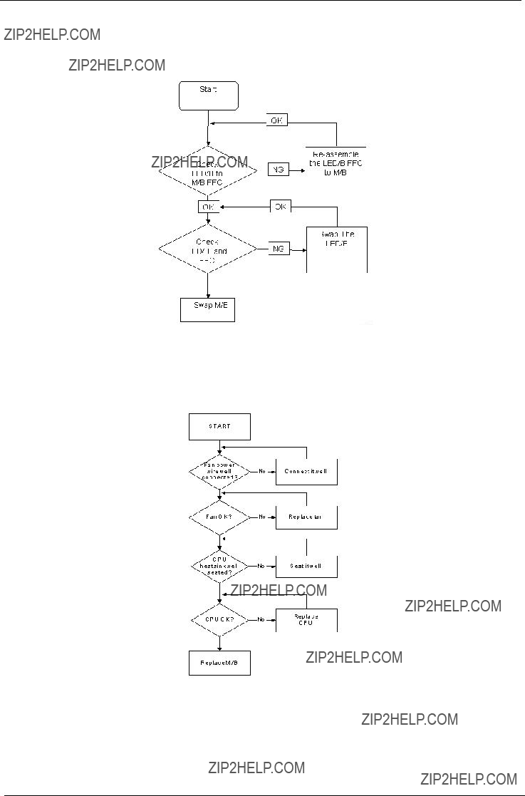
Power On Issue
If the system doesn???t power on, perform the following actions one at a time to correct the problem. Do not replace a
Computer Shutsdown Intermittently
If the system powers off at intervals, perform the following actions one at a time to correct the problem.
1.Check the power cable is properly connected to the computer and the electrical outlet.
2.Remove any extension cables between the computer and the outlet.
3.Remove any surge protectors between the computer and the electrical outlet. Plug the computer directly into a known good electrical outlet.
4.Disconnect the power and open the casing to check the Thermal Unit (see ???Thermal Unit Failure??? on page 142) and fan airways are free of obstructions.
5.Disable the power management settings in the BIOS to ensure they are not the cause of the problem (see ???Boot??? on page 33).
6.Remove all external and
7.Remove any recently installed software.
8.If the Issue is still not resolved, see ???Online Support Information??? on page 185.
No Display Issue
If the Display doesn???t work, perform the following actions one at a time to correct the problem. Do not replace a
No POST or Video
If the POST or video doesn???t display, perform the following actions one at a time to correct the problem.
1.Make sure that the internal display is selected. On this notebook model, switching between the internal display and the external display is done by pressing Fn+F5. Reference Product pages for specific model procedures.
2.Make sure the computer has power by checking at least one of the following occurs:
???Fans start up
???Status LEDs light up
If there is no power, see ???Power On Issue??? on page 130.
3.Drain any stored power by removing the power cable and battery and holding down the power button for 10 seconds. Reconnect the power and reboot the computer.
4.Connect an external monitor to the computer and switch between the internal display and the external display is by pressing Fn+F5 (on this model).
If the POST or video appears on the external display, see ???LCD Failure??? on page 133.
5.Disconnect power and all external devices including port replicators or docking stations. Remove any memory cards and CD/DVD discs. Restart the computer.
If the computer boots correctly, add the devices one by one until the failure point is discovered.
6.Reseat the memory modules.
7.Remove the drives (see ???Disassembly Process??? on page 42).
8.If the Issue is still not resolved, see ???Online Support Information??? on page 185.

Abnormal Video Display
If video displays abnormally, perform the following actions one at a time to correct the problem.
1.Reboot the computer.
2.If permanent vertical/horizontal lines or dark spots display in the same location, the LCD is faulty and should be replaced. See ???Disassembly Process??? on page 42.
3.If extensive pixel damage is present (different colored spots in the same locations on the screen), the LCD is faulty and should be replaced. See ???Disassembly Process??? on page 42.
4.Adjust the brightness to its highest level. See the User Manual for instructions on adjusting settings. NOTE: Ensure that the computer is not running on battery alone as this may reduce display brightness.
If the display is too dim at the highest brightness setting, the LCD is faulty and should be replaced. See ???Disassembly Process??? on page 42.
5.Check the display resolution is correctly configured:
a.Minimize or close all Windows.
b.If display size is only abnormal in an application, check the view settings and control/mouse wheel zoom feature in the application.
c.If desktop display resolution is not normal,
Personalize?? Display Settings.
d.Click and drag the Resolution slider to the desired resolution.
e.Click Apply and check the display. Readjust if necessary.
6.Roll back the video driver to the previous version if updated.
7.Remove and reinstall the video driver.
8.Check the Device Manager to determine that:
???The device is properly installed. There are no red Xs or yellow exclamation marks.
???There are no device conflicts.
???No hardware is listed under Other Devices.
9.If the Issue is still not resolved, see ???Online Support Information??? on page 185.
10.Run the Windows Memory Diagnostic from the operating system DVD and follow the onscreen prompts.
11.If the Issue is still not resolved, see ???Online Support Information??? on page 185.
Random Loss of BIOS Settings
If the computer is experiencing intermittent loss of BIOS information, perform the following actions one at a time to correct the problem.
1.If the computer is more than one year old, replace the CMOS battery.
2.Run a complete virus scan using
3.If the computer is experiencing HDD or ODD BIOS information loss, disconnect and reconnect the power and data cables between devices.
If the BIOS settings are still lost, replace the cables.
4.If HDD information is missing from the BIOS, the drive may be defective and should be replaced.
5.Replace the Motherboard.
6.If the Issue is still not resolved, see ???Online Support Information??? on page 185.

LCD Failure
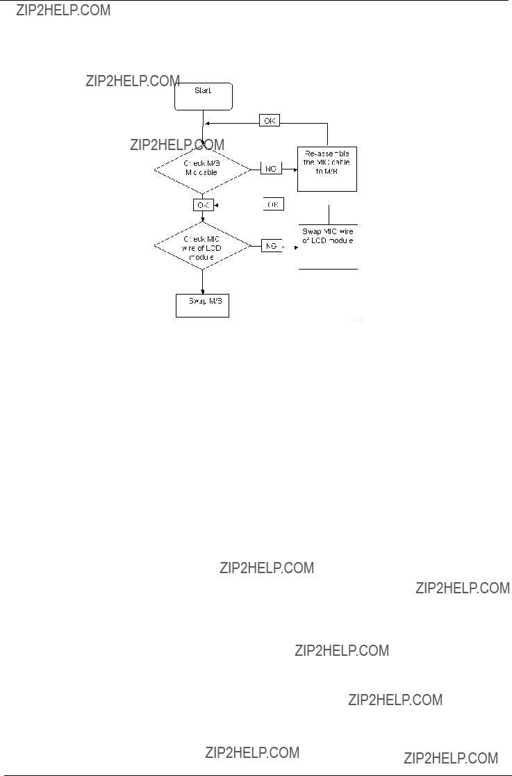
If the LCD fails, perform the following actions one at a time to correct the problem. Do not replace a non- defective FRUs:
If the

Touchpad Failure
If the Touchpad doesn???t work, perform the following actions one at a time to correct the problem. Do not replace a
Internal Speaker Failure
If the internal Speakers fail, perform the following actions one at a time to correct the problem. Do not replace a

Sound Problems
If sound problems are experienced, perform the following actions one at a time to correct the problem.
1.Reboot the computer.
2.Navigate to Start?? Control Panel?? System and Maintenance?? System?? Device Manager. Check the Device Manager to determine that:
???The device is properly installed.
???There are no red Xs or yellow exclamation marks.
???There are no device conflicts.
???No hardware is listed under Other Devices.
3.Roll back the audio driver to the previous version, if updated recently.
4.Remove and reinstall the audio driver.
5.Ensure that all volume controls are set mid range:
a.Click the volume icon on the taskbar and drag the slider to 50. Ensure that the volume is not muted.
b.Click Mixer to verify that other audio applications are set to 50 and not muted.
6.Navigate to Start?? Control Panel?? Hardware and Sound?? Sound. Ensure that Speakers are selected as the default audio device (green check mark).
NOTE: If Speakers does not show,
7.Select Speakers and click Configure to start Speaker Setup. Follow the onscreen prompts to configure the speakers.
8.Remove and recently installed hardware or software.
9.Restore system and file settings from a known good date using System Restore.
If the issue is not fixed, repeat the preceding steps and select an earlier time and date.
10.Reinstall the Operating System.
11.If the Issue is still not resolved, see ???Online Support Information??? on page 185.
Internal Microphone Failure
If the internal Microphone fails, perform the following actions one at a time to correct the problem. Do not replace a
Microphone Problems
If internal or external Microphones do no operate correctly, perform the following actions one at a time to correct the problem.
1.Check that the microphone is enabled. Navigate to Start?? Control Panel?? Hardware and Sound?? Sound and select the Recording tab.
2.
3.The microphone appears on the Recording tab.
4.
5.Select the microphone then click Properties. Select the Levels tab.
6.Increase the volume to the maximum setting and click OK.
7.Test the microphone hardware:
a.Select the microphone and click Configure.
b.Select Set up microphone.
c.Select the microphone type from the list and click Next.
d.Follow the onscreen prompts to complete the test.
8.If the Issue is still not resolved, see ???Online Support Information??? on page 185.

HDD Not Operating Correctly
If the HDD does not operate correctly, perform the following actions one at a time to correct the problem.
1.Disconnect all external devices.
2.Run a complete virus scan using
3.Run the Windows Vista Startup Repair Utility:
a.insert the Windows Vista Operating System DVD in the ODD and restart the computer.
b.When prompted, press any key to start to the operating system DVD.
c.The Install Windows screen displays. Click Next.
d.Select Repair your computer.
e.The System Recovery Options screen displays. Click Next.
f.Select the appropriate operating system, and click Next.
NOTE: Click Load Drivers if controller drives are required.
g.Select Startup Repair.
h.Startup Repair attempts to locate and resolve issues with the computer.
i.When complete, click Finish.
If an issue is discovered, follow the onscreen information to resolve the problem.
4.Run the Windows Memory Diagnostic Tool. For more information see Windows Help and Support.
5.Restart the computer and press F2 to enter the BIOS Utility. Check the BIOS settings are correct and that CD/DVD drive is set as the first boot device on the Boot menu.
6.Ensure all cables and jumpers on the HDD and ODD are set correctly.
7.Remove any recently added hardware and associated software.
8.Run the Windows Disk Defragmenter. For more information see Windows Help and Support.
9.Run Windows Check Disk by entering chkdsk /r from a command prompt. For more information see Windows Help and Support.
10.Restore system and file settings from a known good date using System Restore.
If the issue is not fixed, repeat the preceding steps and select an earlier time and date.
11.Replace the HDD. See ???Disassembly Process??? on page 42.

ODD Failure
If the ODD fails, perform the following actions one at a time to correct the problem. Do not replace a non- defective FRUs:
ODD Not Operating Correctly
If the ODD exhibits any of the following symptoms it may be faulty:
???Audio CDs do not play when loaded
???DVDs do not play when loaded
???Blank discs do not burn correctly
???DVD or CD play breaks up or jumps
???Optical drive not found or not active:
???Not shown in My Computer or the BIOS setup
???LED does not flash when the computer starts up
???The tray does not eject
???Access failure screen displays
???The ODD is noisy
Perform the following general solutions one at a time to correct the problem.
1.Reboot the computer and retry the operation.
2.Try an alternate disc.
3.Navigate to Start?? Computer. Check that the ODD device is displayed in the Devices with Removable Storage panel.
4.Navigate to Start?? Control Panel?? System and Maintenance?? System?? Device Manager.
a.
b.

c.Check that there are no yellow exclamation marks against the items in lDE ATA/ATAPI controllers. If a device has an exclamation mark,
d.Check that there are no yellow exclamation marks against the items in
e.If the exclamation marker is not removed from the item in the lists, try removing any recently installed software and retrying the operation.
Discs Do Not Play
If discs do not play when inserted in the drive, perform the following actions one at a time to correct the problem.
1.Check that the disc is correctly seated in the drive tray and that the label on the disc is visible.
2.Check that the media is clean and scratch free.
3.Try an alternate disc in the drive.
4.Ensure that AutoPlay is enabled:
a.Navigate to Start?? Control Panel?? Hardware and Sound?? AutoPlay.
b.Select Use AutoPlay for all media and devices.
c.In the Audio CD and DVD Movie fields, select the desired player from the drop down menu.
5.Check that the Regional Code is correct for the selected media:
IMPORTANT:Region can only be changed a limited number of times. After Changes remaining reaches zero, the region cannot be changed even Windows is reinstalled or the drive is moved to another computer.
a.Navigate to Start?? Control Panel?? System and Maintenance?? System?? Device Manager.
b.
c.
d.Select the region suitable for the media inserted in the drive.
Discs Do Not Burn Properly
If discs can not be burned, perform the following actions one at a time to correct the problem.
1.Ensure that the default drive is record enabled:
a.Navigate to Start?? Computer and
b.Select the Recording tab. In the Desktop disc recording panel, select the writable ODD from the drop down list.
c.Click OK.
2.Ensure that the software used for burning discs is the factory default. If using different software, refer to the software's user manual.
Playback is Choppy
If playback is choppy or jumps, perform the following actions one at a time to correct the problem.
1.Check that system resources are not running low:
a.Try closing some applications.
b.Reboot and try the operation again.
2.Check that the ODD controller transfer mode is set to DMA:
a.Navigate to Start?? Control Panel?? System and Maintenance?? System?? Device Manager.
b.
c.Click Properties and select the Advanced Settings tab. Ensure that the Enable DMA box is checked and click OK.

d.Repeat for the other ATA Devices shown if applicable.
Drive Not Detected
If Windows cannot detect the drive, perform the following actions one at a time to correct the problem.
1.Restart the computer and press F2 to enter the BIOS Utility.
2.Check that the drive is detected in the ATAPI Model Name field on the Information page.
NOTE: Check that the entry is identical to one of the ODDs specified in ???Hardware Specifications and Configurations??? on page 18.
3.Turn off the power and remove the cover to inspect the connections to the ODD. See ???Disassembly Process??? on page 42.
a.Check for broken connectors on the drive, motherboard, and cables.
b.Check for bent or broken pins on the drive, motherboard, and cable connections.
c.Try an alternate cable, if available. If the drive works with the new cable, the original cable should be replaced.
4.Reseat the drive ensuring and all cables are connected correctly.
5.Replace the ODD. See ???Disassembly Process??? on page 42.
Drive Read Failure
If discs cannot be read when inserted in the drive, perform the following actions one at a time to correct the problem.
1.Remove and clean the failed disc.
2.Retry reading the CD or DVD.
d.Test the drive using other discs.
e.Play a DVD movie
f.Listen to a music CD
If the ODD works properly with alternate discs, the original disc is probably defective and should be replaced.
3.Turn off the power and remove the cover to inspect the connections to the ODD. See ???Disassembly Process??? on page 42.
a.Check for broken connectors on the drive, motherboard, and cables.
b.Check for bent or broken pins on the drive, motherboard, and cable connections.
c.Try an alternate cable, if available. If the drive works with the new cable, the original cable should be replaced.
4.Replace the ODD. See ???Disassembly Process??? on page 42.
Modem Function Failure
If the internal Modem fails, perform the following actions one at a time to correct the problem. Do not replace a
Wireless Function Failure
If the WLAN fails, perform the following actions one at a time to correct the problem. Do not replace a non- defective FRUs:
EasyTouch Button Failure
If the Acer EasyTouch buttons fail, perform the following actions one at a time to correct the problem. Do not replace a
Thermal Unit Failure
If the Thermal Unit fails, perform the following actions one at a time to correct the problem. Do not replace a

External Mouse Failure
If an external Mouse fails, perform the following actions one at a time to correct the problem.
1.Try an alternative mouse.
2.If the mouse uses a wireless connection, insert new batteries and confirm there is a good connection. See the mouse user manual.
3.If the mouse uses a USB connection, try an alternate USB port.
4.Try an alternative program to verify mouse operation. Reinstall the program experiencing mouse failure.
5.Restart the computer.
6.Remove any recently added hardware and associated software.
7.Remove any recently added software and reboot.
8.Restore system and file settings from a known good date using System Restore.
If the issue is not fixed, repeat the preceding steps and select an earlier time and date.
9.Run the Event Viewer to check the events log for errors. For more information see Windows Help and Support.
10.Roll back the mouse driver to the previous version if updated recently.
11.Remove and reinstall the mouse driver.
12.Check the Device Manager to determine that:
???The device is properly installed. There are no red Xs or yellow exclamation marks.
???There are no device conflicts.
???No hardware is listed under Other Devices.
13.If the Issue is still not resolved, see ???Online Support Information??? on page 185.
Other Failures
If the CRT Switch, Dock, LAN Port, external MIC or Speakers, PCI Express Card,
1.Check Drive whether is OK.
2.Check Test Fixture is ok.
3.Swap M/B to Try.

Intermittent Problems
Intermittent system hang problems can be caused by a variety of reasons that have nothing to do with a hardware defect, such as: cosmic radiation, electrostatic discharge, or software errors. FRU replacement should be considered only when a recurring problem exists.
When analyzing an intermittent problem, do the following:
1.Run the advanced diagnostic test for the system board in loop mode at least 10 times.
2.If no error is detected, do not replace any FRU.
3.If any error is detected, replace the FRU. Rerun the test to verify that there are no more errors.
Undetermined Problems
The diagnostic problems does not identify which adapter or device failed, which installed devices are incorrect, whether a short circuit is suspected, or whether the system is inoperative.
Follow these procedures to isolate the failing FRU (do not isolate
NOTE: Verify that the power supply being used at the time of the failure is operating correctly. (See ???Power On Issue??? on page 130.):
1.
2.Visually check them for damage. If any problems are found, replace the FRU.
3.Remove or disconnect all of the following devices:
???
???Printer, mouse, and other external devices
???Battery pack
???Hard disk drive
???DIMM
???
???PC Cards
4.
5.Determine if the problem has changed.
6.If the problem does not recur, reconnect the removed devices one at a time until you find the failing FRU.
7.If the problem remains, replace the following FRU one at a time. Do not replace a
???System board
???LCD assembly

POST Codes Tables
These tables describe the POST codes, drivers, and keys for the POST.
Sec
NO_EVICTION_MODE_DEBUG EQU 1 (CommonPlatform\sec\Ia32\SecCore.inc)
Memory:
DEBUG_BIOS equ 1 (Chipset\Alviso\MemoryInitAsm\IA32\IMEMORY.INC)

BDS & Specific action:

Each PEIM entry point used in 80_PORT
Each Driver entry point used in 80_PORT


Each SmmDriver entry point used in 80_PORT
Chapter 5
Jumper and Connector Locations
Top View

Bottom View

Clearing Password Check and BIOS Recovery
This section provide you the standard operating procedures of clearing password and BIOS recovery for
Aspire 4730Z/4730ZG/4330. Aspire 4730Z/4730ZG/4330 provide one Hardware Open Gap on main board for clearing password check, and one Hotkey for enabling BIOS Recovery.
Clearing Password Check
Hardware Open Gap Description
Steps for Clearing BIOS Password Check
If users set BIOS Password (Supervisor Password and/or User Password) for a security reason, BIOS will ask the password during systems POST or when systems enter to BIOS Setup menu. However, once it is necessary to bypass the password check, users need to short the HW Gap to clear the password by the following steps:
???Power Off a system, and remove HDD, AC and Battery from the machine.
???Open the back cover of the machine, and find out the HW Gap on M/B as picture.
???Use an electric conductivity tool to short the two points of the HW Gap.
???Plug in AC, keep the short condition on the HW Gap, and press Power Button to power on the system till BIOS POST finish. Then remove the tool from the HW Gap.
???Restart system. Press F2 key to enter BIOS Setup menu.
???If there is no Password request, BIOS Password is cleared. Otherwise, please follow the steps and try again.
NOTE: The steps are only for clearing BIOS Password (Supervisor Password and User Password).

BIOS Recovery by Crisis Disk
BIOS Recovery Boot Block:
BIOS Recovery Boot Block is a special block of BIOS. It is used to boot up the system with minimum BIOS initialization. Users can enable this feature to restore the BIOS firmware to a successful one once the previous BIOS flashing process failed.
BIOS Recovery Hotkey:
The system provides a function hotkey: Fn+Esc, for enable BIOS Recovery process when system is powered on during BIOS POST. To use this function, it is strongly recommended to have the AC adapter and Battery present. If this function is enabled, the system will force the BIOS to enter a special BIOS block, called Boot Block.
Steps for BIOS Recovery by Crisis Disk:
Before doing this, one Crisis Disk should be prepared ready in hand. The Crisis Disk could be made by executing the Crisis Disk program in another system with Windows XP OS.
Follow the steps below:
1.Power Off failed system.
2.Attach a USB floppy drive to the failed system.
3.Insert the Crisis Disk in to the USB floppy drive attached to the BIOS flash failed system.
4.In the
The system powers on and the Crisis BIOS Recovery process begins.
BIOS Boot Block begins restoring the BIOS code from the Crisis floppy disk to BIOS ROM on the failed systems.
When the Crisis flash process is finished, the system restarts with a workable BIOS.
5. Update to the latest version BIOS for the system using the regular BIOS flashing process.

Chapter 6
FRU (Field Replaceable Unit) List
This chapter gives you the FRU (Field Replaceable Unit) listing in global configurations of Aspire 4730Z/ 4730ZG/4330. Refer to this chapter whenever ordering for parts to repair or for RMA (Return Merchandise Authorization).
Please note that WHEN ORDERING FRU PARTS, you should check the most
NOTE: To scrap or to return the defective parts, you should follow the local government ordinance or regulations on how to dispose it properly, or follow the rules set by your regional Acer office on how to return it.

Aspire 4730Z/4730ZG/4330 Exploded Diagrams
Main Module

LCD Module

Aspire 4730Z/4730ZG/4330 FRU List
NOTE: The outside housing and color may vary from the mass produced model.


Screw List

Appendix A
Model Definition and Configuration
TravelMate 4730Z/4730ZG/4330 Series


Appendix B
Test Compatible Components
This computer???s compatibility is tested and verified by Acer???s internal testing department. All of its system functions are tested under Windows?? XP Home, Windows?? XP Pro environment.
Refer to the following lists for components, adapter cards, and peripherals which have passed these tests. Regarding configuration, combination and test procedures, please refer to the TravelMate 4730Z/4330 series Compatibility Test Report released by the Acer Mobile System Testing Department.

Microsoft?? Windows?? Vista Environment Test


Appendix C
Online Support Information
This section describes online technical support services available to help you repair your Acer Systems.
If you are a distributor, dealer, ASP or TPM, please refer your technical queries to your local Acer branch office. Acer Branch Offices and Regional Business Units may access our website. However some information sources will require a user i.d. and password. These can be obtained directly from Acer CSD Taiwan.
Acer's Website offers you convenient and valuable support resources whenever you need them.
In the Technical Information section you can download information on all of Acer's Notebook, Desktop and Server models including:
???Service guides for all models
???User's manuals
???Training materials
???Bios updates
???Software utilities
???Spare parts lists
???TABs (Technical Announcement Bulletin)
For these purposes, we have included an Acrobat File to facilitate the
Also contained on this website are:
???Detailed information on Acer's International Traveler's Warranty (ITW)
???Returned material authorization procedures
???An overview of all the support services we offer, accompanied by a list of telephone, fax and email contacts for all your technical queries.
We are always looking for ways to optimize and improve our services, so if you have any suggestions or comments, please do not hesitate to communicate these to us.


Index
A
AFLASH Utility 35
Antennas 104
B
Battery Pack 44
BIOS
ROM size 19 ROM type 19 vendor 19 Version 19
BIOS Passwords Removing 39
BIOS Supports protocol 19 BIOS Utility
Boot 33
Onboard Device Configuration 31 Save and Exit 34
Security 30 System Security 34
Bluetooth module 82 Board Layout
Top View 151 brightness
hotkeys 14
C
Cache
Camera Module 99 caps lock
on indicator 10 Common Problems 130 computer
D
DIMM Module 49
Display 4 display
hotkeys 14
E
EasyTouch Failure 142
Euro 15
External Module Disassembly
Flowchart 43
F
Features 1
Fingerprint Reader Failure 142
Flash Utility 35
FPC Cable 102
FRU (Field Replaceable Unit) List 155
H
Hard Disk Drive Module 52 Hibernation mode
I
I/O Board 80
Indicators 10
Intermittent Problems 144 Internal Microphone Failure 136 Internal Speaker Failure 134 inverter board 97
J
Jumper and Connector Locations 151
Top View 151
K
Keyboard 61
Keyboard Failure 133
L
187

Launch Board 75 LCD Bezel 95 LCD Brackets 102 LCD Failure 133
LCD Module Disassembly Flowchart 94
M
Main Unit Disassembly
Flowchart 58 Mainboard 86 media access
on indicator 10 MediaTouch Button Failure 142 Memory Check 130
Model Definition 166 Modem Board 84 Modem Failure 141
N
No Display Issue 131 Notebook Manager
hotkey 14 num lock
on indicator 10
O
ODD Failure 138
Online Support Information 185 optical drive module 55
P
Panel 5
PC Card 10
Power On Failure 130
S
Speaker Module 76 speakers
hotkey 14 System
Block Diagram 4
T
Test Compatible Components 177 Thermal Unit Failure 142
Top 151
Touch Pad Board Plate 79 Touch Pad Bracket 72 touchpad
hotkey 14 Touchpad Failure 134 Troubleshooting
EasyTouch Buttons 142
Fingerprint Reader 142
Internal Microphone 136
Internal Speakers 134 LCD Failure 133
MediTouch Buttons 142 Modem 141
Other Failures 143 Power On 130
Thermal Unit 142
U
Undetermined Problems 144 utility
BIOS
W
Windows 2000 Environment Test 178
Wireless Function Failure 141
WLAN Board 50
188