Aspire 2000
Service Guide
Service guide files and updates are available on the ACER/CSD web; for more information, please refer to http://csd.acer.com.tw
Service CD P/N.: VD.A20V5.001
PRINTED IN TAIWAN
Aspire 2000
Service Guide
Service guide files and updates are available on the ACER/CSD web; for more information, please refer to http://csd.acer.com.tw
Service CD P/N.: VD.A20V5.001
PRINTED IN TAIWAN

Revision History
Please refer to the table below for the updates made on Aspire 2000 service guide.
II

Copyright
Copyright ?? 2003 by Acer Incorporated. All rights reserved. No part of this publication may be reproduced, transmitted, transcribed, stored in a retrieval system, or translated into any language or computer language, in any form or by any means, electronic, mechanical, magnetic, optical, chemical, manual or otherwise, without the prior written permission of Acer Incorporated.
Disclaimer
The information in this guide is subject to change without notice.
Acer Incorporated makes no representations or warranties, either expressed or implied, with respect to the contents hereof and specifically disclaims any warranties of merchantability or fitness for any particular purpose. Any Acer Incorporated software described in this manual is sold or licensed "as is". Should the programs prove defective following their purchase, the buyer (and not Acer Incorporated, its distributor, or its dealer) assumes the entire cost of all necessary servicing, repair, and any incidental or consequential damages resulting from any defect in the software.
Acer is a registered trademark of Acer Corporation. Intel is a registered trademark of Intel Corporation.
Pentium and Pentium II/III are trademarks of Intel Corporation.
Other brand and product names are trademarks and/or registered trademarks of their respective holders.
III

Conventions
The following conventions are used in this manual:
IV

Preface
Before using this information and the product it supports, please read the following general information.
1.This Service Guide provides you with all technical information relating to the BASIC CONFIGURATION decided for Acer's "global" product offering. To better fit local market requirements and enhance product competitiveness, your regional office MAY have decided to extend the functionality of a machine (e.g.
2.Please note WHEN ORDERING FRU PARTS, that you should check the most
V

Table of Contents
Features . . . . . . . . . . . . . . . . . . . . . . . . . . . . . . . . . . . . . . . . . . . . . . . . . . . . . . . .1
System Block Diagram . . . . . . . . . . . . . . . . . . . . . . . . . . . . . . . . . . . . . . . . . . . . .3
Board Layout . . . . . . . . . . . . . . . . . . . . . . . . . . . . . . . . . . . . . . . . . . . . . . . . . . . .4
Top View . . . . . . . . . . . . . . . . . . . . . . . . . . . . . . . . . . . . . . . . . . . . . . . . . . . .4
Rear View . . . . . . . . . . . . . . . . . . . . . . . . . . . . . . . . . . . . . . . . . . . . . . . . . . .5
Outlook View . . . . . . . . . . . . . . . . . . . . . . . . . . . . . . . . . . . . . . . . . . . . . . . . . . . . .6
Open View . . . . . . . . . . . . . . . . . . . . . . . . . . . . . . . . . . . . . . . . . . . . . . . . . .6
Front Panel . . . . . . . . . . . . . . . . . . . . . . . . . . . . . . . . . . . . . . . . . . . . . . . . . .7
Top Panel . . . . . . . . . . . . . . . . . . . . . . . . . . . . . . . . . . . . . . . . . . . . . . . . . . .8
Left Panel . . . . . . . . . . . . . . . . . . . . . . . . . . . . . . . . . . . . . . . . . . . . . . . . . . .9
Right Panel . . . . . . . . . . . . . . . . . . . . . . . . . . . . . . . . . . . . . . . . . . . . . . . . .10
Rear Panel . . . . . . . . . . . . . . . . . . . . . . . . . . . . . . . . . . . . . . . . . . . . . . . . . .9
Indicators . . . . . . . . . . . . . . . . . . . . . . . . . . . . . . . . . . . . . . . . . . . . . . . . . . . . . .13
Keyboard . . . . . . . . . . . . . . . . . . . . . . . . . . . . . . . . . . . . . . . . . . . . . . . . . . . . . .15
Special keys . . . . . . . . . . . . . . . . . . . . . . . . . . . . . . . . . . . . . . . . . . . . . . . .15
Embedded Numberic Keypad . . . . . . . . . . . . . . . . . . . . . . . . . . . . . . . . . . . . . . .16
Windows Keys . . . . . . . . . . . . . . . . . . . . . . . . . . . . . . . . . . . . . . . . . . . . . . . . . . .17
Hot Keys . . . . . . . . . . . . . . . . . . . . . . . . . . . . . . . . . . . . . . . . . . . . . . . . . . . . . . .18
The Euro Symbol . . . . . . . . . . . . . . . . . . . . . . . . . . . . . . . . . . . . . . . . . . . . . . . .19
Touchpad . . . . . . . . . . . . . . . . . . . . . . . . . . . . . . . . . . . . . . . . . . . . . . . . . . . . . .19
Touchpad Basics . . . . . . . . . . . . . . . . . . . . . . . . . . . . . . . . . . . . . . . . . . . .20
Launch Keys . . . . . . . . . . . . . . . . . . . . . . . . . . . . . . . . . . . . . . . . . . . . . . . . . . . .22
Hardware Specifications and Configurations . . . . . . . . . . . . . . . . . . . . . . . . . . .23
BIOS Setup Utility . . . . . . . . . . . . . . . . . . . . . . . . . . . . . . . . . . . . . . . . . . . . . . . .37
Navigating the BIOS Setup Utility . . . . . . . . . . . . . . . . . . . . . . . . . . . . . . . .37
Main . . . . . . . . . . . . . . . . . . . . . . . . . . . . . . . . . . . . . . . . . . . . . . . . . . . . . . 40
Advanced . . . . . . . . . . . . . . . . . . . . . . . . . . . . . . . . . . . . . . . . . . . . . . . . . .41
Security . . . . . . . . . . . . . . . . . . . . . . . . . . . . . . . . . . . . . . . . . . . . . . . . . . . .44
Boot . . . . . . . . . . . . . . . . . . . . . . . . . . . . . . . . . . . . . . . . . . . . . . . . . . . . . . .46
Exit . . . . . . . . . . . . . . . . . . . . . . . . . . . . . . . . . . . . . . . . . . . . . . . . . . . . . . .47
BIOS Flash Utility . . . . . . . . . . . . . . . . . . . . . . . . . . . . . . . . . . . . . . . . . . . . . . . .48
System Diagnostic Diskette . . . . . . . . . . . . . . . . . . . . . . . . . . . . . . . . . . . . . . . .48
VII

Table of Contents
System Check Procedures . . . . . . . . . . . . . . . . . . . . . . . . . . . . . . . . . . . . . . . . .62 External Diskette Drive Check . . . . . . . . . . . . . . . . . . . . . . . . . . . . . . . . . .62 External
Insyde MobilePro BIOS POST Beep code and POST Messages . . . . . . . . . . .67 Index of
VIII

Chapter 1
System Specifications
Features
This computer was designed with the user in mind. Here are just a few of its many features:
Performance
!Intel?? Pentium M processor at 1.4 ~ 1.7 GHz or higher
!Intel 855PM + Intel
!PC2700 DDR SDRAM, Maximum memory up to 2GB (with two 1024MB
!Internal
!
!
!Power management system with ACPI (Advanced Configuration Power Interface)
Display
!
!3D graphics engine
!Simultaneous LCD and CRT display support
!
!Dual display capability
Multimedia
!
!
!
Connectivity
!
!Ethernet/Fast Ethernet port
!Fast infrared wireless communication
!3 USB 2.0 (Universal Serial Bus) ports
!IEEE 1394 port
!Intel 802.11b or 802.11a/b wireless LAN (manufacturing optional)
!Bluetooth ready (manufacturing optional)
Expansion
!One type II CardBus PC Card slot
!Upgradeable memory
I/O Ports
!One Infrared (FIR)
!One

!One
!
!One
!One
!One external monitor port
!One
!One
!One
!Three Universal Serial Bus (USB) ports
!One IEEE 1394 port

System Block Diagram
Board Layout
Top View
Rear View


Outlook View
A general introduction of ports allow you to connect peripheral devices, as you would with a desktop PC.
Open View

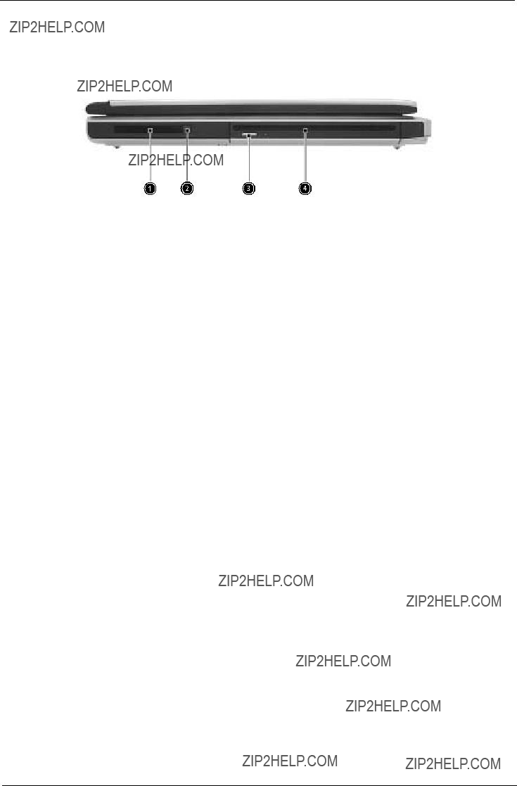
Front Panel

Top Panel
Left Panel

Right Panel
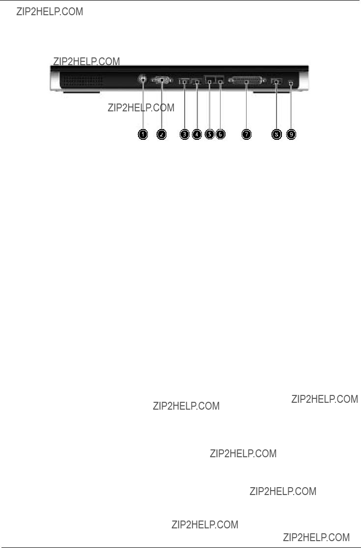
Rear Panel

Bottom View

Indicators
Your computer provides an array of three indicators located above the keyboard, in addition to four indicators positioned at the front of the palm rest area. These indicators show the status of the computer and its componetns.
The three indicators located above the keyboard provide the following status information:
NOTE: The keypad lock must be turned on to use the embedded numeric keypad.
The four indicators located at the front of the unit provide the following status information:

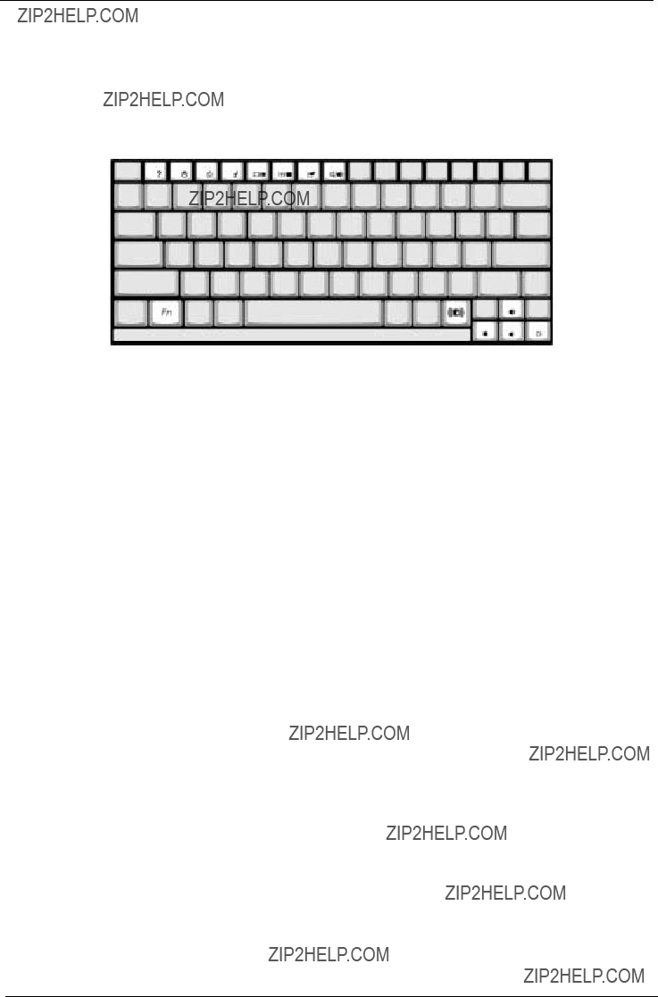
Keyboard
The keyboard features
Special keys
Lock keys
The computer features three lock keys, each with its own status indicator light.
NOTE: Scroll Lock doesn???t work in all applications. Toggle on and off by pressing the Fn+F12 keys
simultaneously.

Embedded Keypad
The embedded keypad functions like a desktop numeric keypad. It is indicated by small blue numbers and on the applicable keys.
To use the the embedded numeric keys, toggle the Num Lock on by pressing the Fn + F11 keys simultaneously.
With the embedded keypad turned on, the following actions are possible:

Windows Keys
The keyboard features two keys that perform
+ E (Opens the My Computer window)
+ F1 (opens Help and Support)
+ F (opens the Find: All Files dialog box)
Hotkeys
Using the Fn key with another key creates a hot key, providing a quick and convenient method for controlling various functions.
To use a hot key, first hold down the Fn key. Next, press the second key in combination. Finally, release both keys.
NOTE: When activating hotkeys, press and hold the Fn key before pressing the other key in the hotkey combination.

Euro key
Your computer supports the new Euro currency character. First, hold down the Alt Gr key, and then press the Euro key.
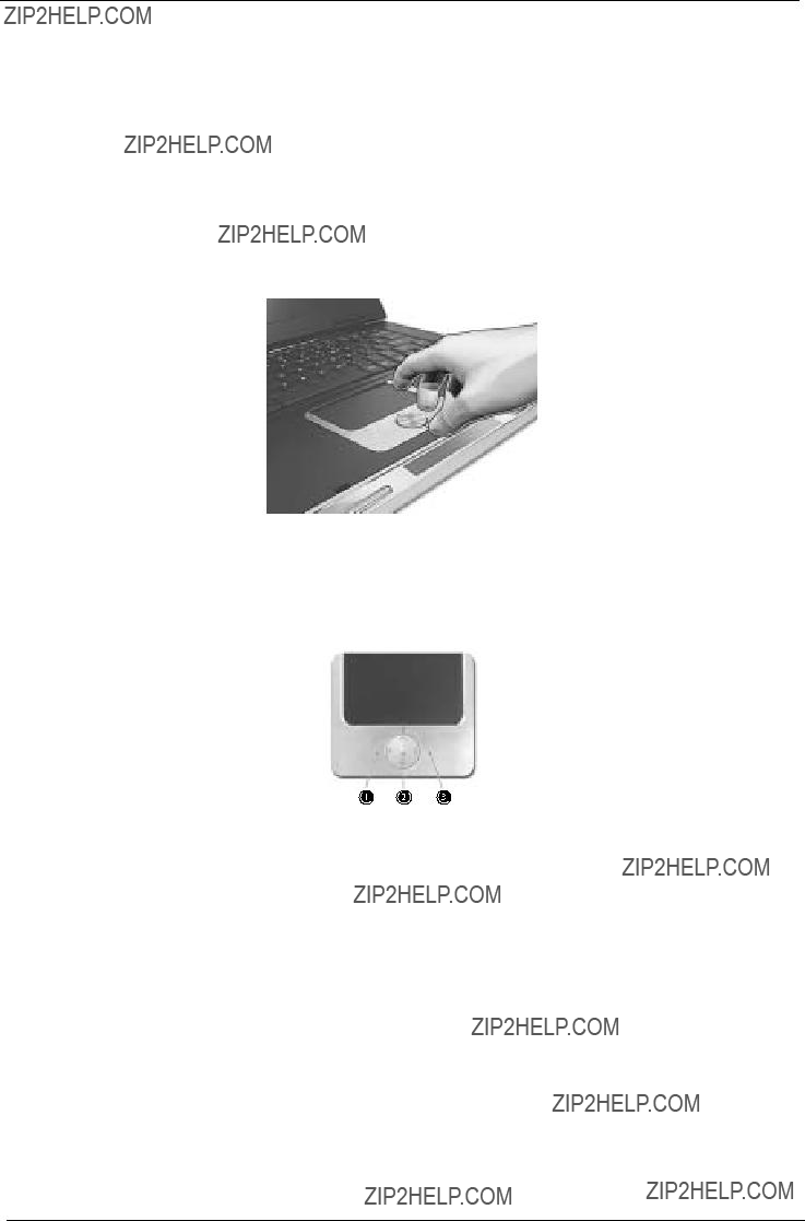
Touchpad
The
The cursor responds to your finger movements on the touchpad. In addition, the two click buttons provide the same functionality as a computer mouse, while the scroll key enables easy up and down scrolling in documents and web pages.
The touchpad is located in the middle of the palm rest area, providing maximum comfort and efficiency.
Touchpad Basics
Use the touchpad as follows:
!Slide your finger over the surface of the touchpad to control the movement of the cursor. Tap the touchpad to perform selection and execution functions.
!Press the left (1) and right (3) buttons to perform selection and execution functions, just as you would use the buttons on a computer mouse.
!Use the scroll key (2) to scroll through long documents and web pages. Press the top of the key to scroll up, and the bottom to scroll down; left to scroll left, and right to scroll right.

NOTE: Keep your fingers, as well as the surface of the touchpad dry and clean. The touchpad is sensitive to your finger movements: the lighter the touch, the better the response. Tapping hard will not increase the touchpad???s responsiveness.

Launch Keys
Located at the top of the keyboard are four buttons, in addition to the power button. These buttons are called launch keys. They are designed as key 1, key 2, key 3 and key 4, from right to left. By default, key 1 is used to launch the email application and key 2 is used to launch the Internet browser. Key 3 and key 4 start the Launch Manager application. The first four launch keys can be set by the user. To set the launch keys, run the Acer Launch Manager.

Hardware Specifications and Configurations
Processor
Memory Combinations
NOTE: Above table lists some system memory configurations. You may combine DIMMs with various capacities to form other combinations.
.
LAN Interface

Hard Disk Drive Interface
Optical Drive Interface

Audio Interface
Video Resolution Mode (for both LCD and CRT)

USB Port

Battery
There are two control signals that come form system to control lamp brightness. One signal is named DAC_BRIG, which limits current to meet LCD lamp current specification. Another one is named PWM, which adjusts lamp brightness. This inverter brightness is adjusted by PWM burst mode. The PWM burst mode is that turning on and off the lamp at rate of 150Hz. The effective brightness is a function of the duty cycle.
Features
1.Wide range 9V to 21V input voltage.
2.Birghtness adjustment by PWM duty mode.
3.Close loop controls lamp current.

Electrical Characteristics

*1. The inverter can work in 7.5V input voltage (continuous), but 7.5V electronic characteristic will not be care.
*2. Limited lamp maximum current by DAC_BRIC signal:
When DAC_BRIG voltage is 0V and INV_PWM enables (100%), lamp has max. current. When DAC_BRIG voltage is 3.3V and INV_PWM enables (100%), lamp has min. current. When add 1V DAC, the 100% Lamp current will decrease 0.5mA.
DAC_BRIG signal comes from system chipset with internal resistance of 3K ???
*3. Inverter operating frequency should be within specification (45~65kHz) at max. and min. brightness load.
*4. INV_PWM enable implies INV_PWM signal is High level (On duty cycle is 100%). It is a square wave of 150Hz to adjust backlight brightness that is a function of PWM duty cycle. Backlight brightness is maximum value under INV_PWM at 100% and brightness is minimum under INV_PWM at 30%.
*5.The system interface signals belong to 3.3V.
*6. Please make sure open lamp output voltage should be within starting voltage specification. *7. Inverter should pass human body safety test.
*8. Inverter should be no smoking by any component open/short test.
*9. Transformer voltage stress should not be over 85% under any condition. (turn on overshoot transient and line transient.)
*10. Audio noise should be less than 36dB at 10cm distance.

.
Electrical specification
Thermal
All components on inverter board should follow below rules:
1.Component using conditions (component stress) must be within component specification including voltage rating, current rating, temperature etc.
2.Component temperature should follow below:
!???T <=450 degree C, at 25, 35 degree C.
!Component temperature should be less than 80 degree C inside system at 35 degree C.
LCD

AC Adapter

Power Management
Memory Address Map

I/O Address Map

IRQ Assignment Map

Chapter 2
System Utilities
BIOS Setup Utility
The BIOS Setup Utility is a hardware configuration program built into your computer???s BIOS (Basic Input/ Output System).
Your computer is already properly configured and optimized, and you do not need to run this utility. However, if you encounter configuration problems, you may need to run Setup. Please also refer to Chapter 4 Troubleshooting when problem arises.
To activate the BIOS Utility, press mduring POST (when ???Press <F2> to enter Setup??? message is prompted on the bottom of screen).
The setup screen displays BIOS as follows:
Navigating the BIOS Utility
There are five menu options: Main, Advanced, Security, Boot and Exit.
Follow these instructions:
!To choose a menu, use the cursor left/right keys (zx).
!To choose a parameter, use the cursor up/down keys ( wy).
!To change the value of a parameter, press p or q.
!Press ^ while you are in any of the menu options to go to the Exit menu.
!In any menu, you can load default settings by pressing t. You can also press uto save any changes made and exit the BIOS Setup Utility.
NOTE: You can change the value of a parameter if it is enclosed in square brackets. Navigation keys for a particular menu are shown on the bottom of the screen. Help for parameters are found in the Item Specific Help part of the screen. Read this carefully when making changes to parameter values.

Setup system date, time. Enable boot logo and get system information.

Memory

Main
This menu provides you the information of the system.
<Tab> <Right> <Left> for block select. <Up> <Down> for item select.
< Enter> for accept. <Cancel> <Esc> for reject. <Alt> activates accelerators. <Space> for Enable or Disable.

Advanced
The Advanced screen contains parameters involving your hardware devices. It also provides advanced settings of the system.
FIR Ports
Configure the system???s infrared port using options: Disabled and Enabled.
( ) Normal (16550)
( ) IrDA (HPSIR)
() ASK IR
( ) FAST IR
<Tab> <Right> <Left> for block select. <Up> <Down> for item select.
< Enter> for accept. <Cancel> <Esc> for reject. <Alt> activates accelerators. <Space> for Enable or Disable.
The table below describes the parameters in the screen. Settings in boldface are the default and suggested parameter settings.

LPT Port
Configure the system???s parallel port using options: Disabled and Enabled.

Legacy USB Support
Disabled: Disable support for Legacy Universal Serial Bus.
Enabled: Enable support for Legacy Universal Serial Bus.
( ) DMA1
Legacy USB keyboard Floppy Disk USB Mouse Support <Space> for Enable or Disable
Security
The Security screen contains parameters that help safeguard and protect your computer from unauthorized use.
Enter new password. Password will NOT be displayed
The table below describes the parameters in this screen. Settings in boldface are the default and suggested parameter settings.
Set Supervisor/User Password
If password on boot is required, the password must be set otherwise it cannot be enabled.


Boot
This menu allows the user to decide the order of boot devices to load the operating system. Bootable devices includes the distette drive in module bay, the onboard hard disk drive and the
in module bay.
Please select the order of the boot devices
<Tab> <Right> <Left> for block select. <Up> <Down> for item select.
< Enter> for accept. <Cancel> <Esc> for reject. <Alt> activates accelerators. <Space> for Enable or Disable.
.

Exit
The Exit screen contains parameters that help safeguard and protect your computer from unauthorized use.
<Tab> <Right> <Left> for block select. <Up> <Down> for item select.
< Enter> for accept. <Cancel> <Esc> for reject. <Alt> activates accelerators. <Space> for Enable or Disable.
The table below describes the parameters in this screen.

BIOS Flash Utility
The BIOS flash memory update is required for the following conditions:
!New versions of system programs
!New features or options
!Restore a BIOS when it becomes corrupted. Use the Flash utility to update the system BIOS flash ROM.
NOTE: If you do not have a crisis recovery diskette at hand, then you should create a Crisis Recovery
Diskette before you use the Flash utility.
NOTE: Do not install
NOTE: Please use the AC adaptor power supply when you run the Flash utility. If the battery pack does not contain enough power to finish BIOS flash, you may not boot the system because the BIOS is not completely loaded.
Fellow the steps below to run the Flash.
1.Prepare a bootable diskette.
2.Copy the Flash utilities to the bootable diskette.
3.Then boot the system from the bootable diskette. The Flash utility has
System Diagnostic Diskette
This diagnostic diskette is for the Acer Aspire 2000 series notebook machine. However, system diagnostic utility is not ready as service CD released. Acer HQ CSD will upload the utility to CSD website as soon as it is ready.

Chapter 3
Machine Disassembly and Replacement
This chapter contains
To disassemble the computer, you need the following tools:
!Wrist grounding strap and conductive mat for preventing electrostatic discharge
!small Philips screwdriver
!flat head screwdriver
!Philiips screwdriver
!nut screwdriver
!tweezers
NOTE: The screws for the different components vary in size. During the disassembly process, group the screws with the corresponding components to avoid mismatch when putting back the components.
When you remove the stripe cover, please be careful not to scrape the cover.

General Information
Before You Begin
Before proceeding with the disassembly procedure, make sure that you do the following:
1.Turn off the power to the system and all peripherals.
2.Unplug the AC adapter and all power and signal cables from the system.
3.Remove the battery pack.

Disassembly Procedure Flowchart
AM2.5x5
M2.0x4
BM2.5x3
CM2.5x4
DM2.5x10
M2.5x4

Aspire 2000 Disassembly Procedure
This section will guide you how to disassemble the system when you need to perform system service. Please also refer to the disassembly video, if availabled.
CAUTION: Before you proceed,make sure you have turned off the system and all peripherals connected.
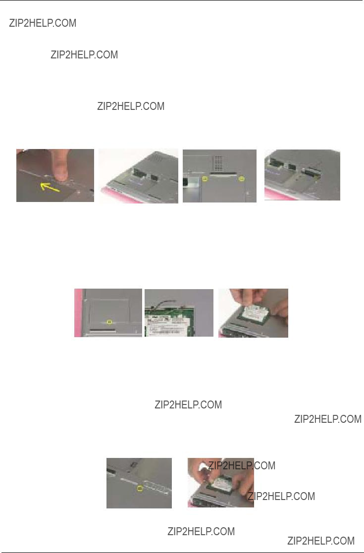
Disassemble the Battery and HDD
1.Release the battery lock and slide the battery latch.
2.Then remove the battery pack.
3.Remove the two screws to release the hard drive door.Then take it away.
Disassemble the Wireless
1.Remove the one screw to release the mini door, and take it away.
2.Disconnect the two wireless cables.
3.Then take the wireless board from the base.
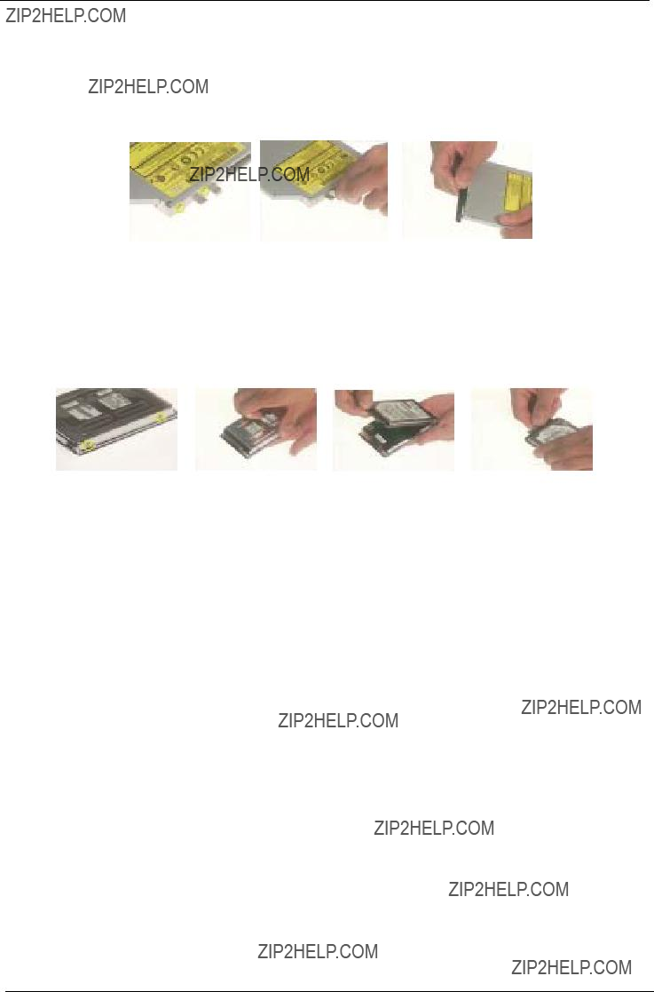
Disassemble the RAM and ODD
1.Remove the one screw to release the RAM door and remove it.
2.Press down the both side latches to release the RAM board.
3.Remove the one screw to release the ODD module.
4.Then push the inner position to remove the ODD from the base.
5.Pull the entire ODD moudle from the system.
Disassemble the Middle Cover Board
1.Remove the one screw.
2.Detach the middle cover from the unit with the flat screw driver.
3.Disconnect the system cable from the middle cover board.
4.Remove the two screws to release the middle cover board.
5.Then detach the middle cover board from cover.
Disassemble the Keyboard
1.Remove the screws on each side.
2.Pull up both sides of the latches to disconnect the FFC from the mainboard.
3.Remove the screws on each side to release the keyboard bracket.
4.Then take the keyboard supporter bracket from the system.

Disassemble the LCD
1.Remove the one screw from the LVDS board.
2.Pull the LCD coaxial board and the cable from the system.
3.Remove the two screws from the hinge on each side to release the LCD panel.
4.Pull the entire LCD module from the system.
Disassemble the MDC and RAM
1.Remove the two screws to release the MDC board.
2.Disconnect the MDC cable before you take the MDC board.
3.Press down the both sides latches to release the RAM.
4.Disconnect the right and left speaker cables from the mainboard.
5.Disconnect the touchpad FPC connector and CPU fan cable.
Disassemble the Upper Case
1.Remove the thirteen screws located on the base case.
2.Remove the two screws on the other side to located on the rear panel.
3.Remove the three screws to release the upper case.
4.Detach the upper case from the system.

Disassemble the Main Unit ( Touchpad, Bluetooth and LCM Board)
1.Remove the seven screws to release the touchpad supporter bracket.
2.Disconnect the touchpad FPC connector.
3.Disconnect the cable as highlights.
4.Then detach the touchpad bracket from the position.
5.Detach the touchpad PC from the module.
6.Disconnect the bluetooth board FFC connector.
7.Remove the two screws to release the bluetooth board.
8.Take the bluetooth board from the system.
9.Remove the one screw to release the LCM board.
10.Detach the LCM board from the system.

Disassemble the Main Unit ( Speakers, Fan, Thermal and CPU)
1.Remove the one screw to release the up hinge saddle.
2.Remove the three screws to release the bottom hinge saddle.
3.Detach the right hinge saddle from the case.
4.Remove the two screws to release the right hinge saddle.
5.Take the right speaker from the opsition.
6.Remove the one screw to release the CPU fan from the hinge saddle.
7.Take the CPU fan from the hinge saddle.
8.Remove the three screws to release the left hinge saddle.
9.Detach the left hinge saddle from the system.
10.Remove the one screw to release the left speaker from the base cover.
11.Then detach the left speaker.
12.Remove the four screws to release the thermal module.
13.Detach the thermal module from the system.
14.Remove the one screw to release the CPU.
15.Detach the CPU fan from the socket.

Disassemble the Main Unit ( VGA, Card Reader,
1.Remove the one screw to release the VGA bracket.
2.Detach the VGA module from the mainboard.
3.Separate the VGA bracket and the VGA board.
4.Remove the ground screw to release the card reader.
5.Disconnect the card reader cables on each side.
6.Disconnect the
7.Remove the screws on each side to release the
8.Detach the
9.Detach the card reader board from the case.
10.Remove the one screw to release the mainboard.
11.Press the PCMCIA button and hold the position to release the mainboard from the case.

Disassemble the LCD Module
1.Remove the screws on each side.
2.Detach the bezel from the LCD panel.
3.Remove the screws located on the different side.
4.Detach the LCD panel from the cover.
5.Take the antenna away from the position to release the inverter board.
6.Disconnect the LCD coaxial cables.
7.Remove the four screws to release the left LCD bracket.
8.Take the left LCD bracket from the panel.
9.Remove the four screws to release the right LCD bracket.
10.Take the right LCD bracket from the panel.
Disassemble the ODD Module
1.Remove the two screws to separate the ODD drive.
2.Detach the ODD bracket.
3.Detach the ODD door.
Disassemble the HDD Module
1.Remove the two screws on each side.
2.Separate the hard disk top cover and take the hard drive from the carrier.
3.Remove the hard disk connector from the rear position.

Chapter 4
Troubleshooting
Use the following procedure as a guide for computer problems.
1.Obtain the failed symptoms in as much detail as possible.
2.Verify the symptoms by attempting to
3.If any problem occurs, you can perform visual inspection before you fellow this chapter???s instructions. You can check the following:
power cords are properly connected and secured; there are no obvious shorts or opens;
there are no obviously burned or heated components; all components appear normal.
4.After you perform visual inspection you can also verify the following:
ask the user if a password is registered and, if it is, ask him or her to enter the password.
verify with the customer that Wndows XP is installed on the hard disk. Operating systems that were not preinstalled by Acer can cause malfunction.
make sure all optional equipment is removed from the computer. make sure the floppy disk is empty.
5.Use the following table with the verified symptom to determine which page to go to.

System Check Procedures
External Diskette Drive Check
Do the following steps to isolate the problem to a controller, driver, or diskette. A
NOTE: Make sure that the diskette does not have more than one label attached to it. Multiple labels can cause damage to the drive or cause the drive to fail.
Do the following to select the test device.
1.The FDD heads can become dirty over time, affecting their performance. Use an FDD cleaning kit to clean the heads. If the FDD still does not function properly after cleaning, go to next step.
2.Boot from diagnostic program.
3.If an error occurs with the internal diskette drive, reconnect the diskette connector on the main board.
If the error still remains:
1.Reconnect the external diskette drive module.
2.Replace the external diskette drive module.
3.Replace the main board.
External
Do the following to isolate the problem to a controller, drive, or
Do the following to select the test device:
1.Insert an audio CD into the CD/DVD drive. If the CD/DVD drive can read the data from the audio CD. The drive does not have problem, then go to next step. If the CD/DVD LED on the front panel does not emit light as it read the data from the audio CD, then go to next step. However, if the CD/DVD drive can not read data from the audio CD, you may need to clean the CD/DVD drive with a CD/DVD drive cleaning disk.
2.Make sure that the appropriate driver has been installed on the computer for the CD/DVD drive.
3.Boot from the diagnostics diskette and start the diagnostics program
4.See if
5.Follow the instructions in the message window.
If an error occurs, reconnect the connector on the main board. If the error still remains:
1.Reconnect the
2.Replace the
3.Replace the main board.

Keyboard or Auxiliary Input Device Check
Remove the external keyboard if the internal keyboard is to be tested.
If the internal keyboard does not work or an unexpected character appears, make sure that the flexible cable extending from the keyboard is correctly seated in the connector on the main board.
If the keyboard cable connection is correct, run the Keyboard Test.
If the tests detect a keyboard problem, do the following one at a time to correct the problem. Do not replace a
1.Reconnect the keyboard cables.
2.Replace the keyboard.
3.Replace the main board.
The following auxiliary input devices are supported by this computer:
!Embedded Numeric Keypad
!External keyboard
If any of these devices do not work, reconnect the cable connector and repeat the failing operation.
Memory Check
Memory errors might stop system operations, show error messages on the screen, or hang the system. Currently, we do not provide memory test program. However, if you need to check memory but have no testing program or diagonositc utility at hand, please go to http://www.passmark.com to download the shareware ???BurnIn Test V.3.0???. You may test the memory with this program under Window XP environment.
NOTE: Make sure that the DIMM is fully installed into the connector. A loose connection can cause an error.
Power System Check
To verify the symptom of the problem, power on the computer using each of the following power sources:
1.Remove the battery pack.
2.Connect the power adapter and check that power is supplied.
3.Disconnect the power adapter and install the charged battery pack; then check that power is supplied by the battery pack.
If you suspect a power problem, see the appropriate power supply check in the following list:
!???Check the Power Adapter???
!???Check the Battery Pack???
Check the Power Adapter
Unplug the power adapter cable from the computer and measure the output voltage at the plug of the power adapter cable. See the following figure
Pin 1: 19V
Pin 2: 0V, Ground
1.If the voltage is not correct, replace the power adapter.
2.If the voltage is within the range, do the following:
!Replace the main board.
!If the problem is not corrected, see ???Undetermined Problems???.
!If the voltage is not correct, go to the next step.
NOTE: An audible noise from the power adapter does not always indicate a defect.
3.If the
4.If the operational charge does not work, see ???Check the Power Adapter??? .

Check the Battery Pack
To check the battery pack, do the following:
From Software:
1.Check out the Power Options in control Panel
2.In Power Meter, confirm that if the parameters shown in the screen for Current Power Source and Total Battery Power Remaining are correct.
3.Repeat the steps 1 and 2, for both battery and adapter.
4.This helps you identify first the problem is on recharging or discharging.
From Hardware:
1.Power off the computer.
2.Remove the battery pack and measure the voltage between battery terminals 1(+) and 6(ground).
3.If the voltage is still less than 7.5 Vdc after recharging, replace the battery.
4.If the voltage is within the normal range, run the diagnostic program.
To check the battery charge operation, use a discharged battery pack or a battery pack that has less than 50% of the total power remaining when installed in the computer.
If the battery status indicator does not light up, remove the battery pack and let it return to room temperature.
If the charge indicator still does not emit, replace the battery pack. If the charge indicator still does not light up, replace the DC/DC charger board.
Touchpad Check
If the touchpad doesn???t work, do the following actions one at a time to correct the problem. Do not replace a
1.After rebooting, run Touch pad/PS2 Mode Driver.
2.Run utility with the PS/2 mouse function and check if the mouse is working.
3.If the PS/2 mouse does not work, then check if the main board to switch board FPC is connected well.
4.If the main board to switch board FPC is connected well, then check if the touch pad FPC connects to the main board properly.
5.If there is still an error after you have connected the touch pad FPC to the main board properly, then replace the touch pad or touch pad FPC. The touch pad or touch pad FPC may be damaged.
6.Replace switch board.
7.If the touch pad still does not work, then replace the FPC on Track Pad PCB.
After you use the touchpad, the pointer drifts on the screen for a short time. This
Display Check
1.Connect an external display to the computer???s external monitor port, the boot the computer. The computer can automatically detect the external display. Press Fn+ p to switch to the external display.
2.If the external display works fine, the internal LCD may be damaged. Then perform the following steps:
Make sure the DDRRAM module is seated properly. Then run the diplay test again. If the problem still exists, go to next step.
Replace the inverter board, then run the display test program again. If the problem still occurs, go on next step.
Replace the LCD module with a new one then run the display test again. If the probelm still happens, continue next step.
Replace LCD/FL cable with a new one then execute the display diagnostic again. If the problem

still occurs, continue next step.
Replace the CPU with another of the same specifications. If the problems still occurs, go to next step.
The main board may be damaged. Replace main board.
3.If the external monitor has the same problem as the internal monitor, the main board may be damaged. Please insert the diagnostic disk and run the display test program and go through the
Sound Check
To determine if the computer???s
1.Try different audio sources. For example, employ audio CD and ditital music file to determine whether the fault is in the speaker system or not. If not all sources have sound problem, the problem is in the source devices. If all have the same problem, continue next step.
2.Connect a set of earphone or external speakers. If these devices work fine, go to next step. If not, then the main board may be defective or damaged. Replace the main board.
3.Follow the disassembling steps in Chapter 3. Esure the speaker cable is firmly connected to the main board. If the speaker is still a malfunction, go on next step.
4.If the speakers do not sound properly, the speakers may be defective or damaged. Replace the speakers. If the problem still occurs, then replace the main board.

Insyde MobilePro BIOS POST Beep Code and POST Messages
The POST error message index lists the error message and their possible causes. The most likely cause is listed first.
NOTE: Perform the FRU replacement or actions in the sequence shown in FRU/Action column, if the FRU replacement does not solve the problem, put the original part back in the computer. Do not replace a
This index can also help you determine the next possible FRU to be replaced when servicing a computer. If the symptom is not listed, see ???Undetermined Problems??? on page 73.
The following lists the error messages that the BIOS displays on the screen and the error symptoms classified by function.
NOTE: Most of the error messages occur during POST. Some of them display information about a hardware device, e.g., the amount of memory installed. Others may indicate a problem with a device, such as the way it has been configured.
NOTE: If the system fails after you make changes in the BIOS Setup Utility menus, reset the computer, enter Setup and install Setup defaults or correct the error.


Index of


Power


Intermittent Problems
Intermittent system hang problems can be caused by a variety of reasons that have nothing to do with a hardware defect, such as: cosmic radiation, electrostatic discharge, or software errors. FRU replacement should be considered only when a recurring problem exists.
When analyzing an intermittent problem, do the following:
1.Run the diagnostic test for several times to isolate the problem.
2.If no error is detected, do not replace any FRU.
3.If any error is detected, replace the FRU. Rerun the test to verify that there are no more errors.
Undetermined Problems
The diagnostic problems does not identify which adapter or device failed, which installed devices are incorrect, whether a short circuit is suspected, or whether the system is inoperative.
Follow these procedures to isolate the failing FRU (do not isolate
1.
2.Visually check them for damage. If any problems are found, replace the FRU.
3.Remove or disconnect all of the following devices:
!
!Printer, mouse, and other external devices
!Battery pack
!Hard disk drive
!DIMM
!
!PC Cards
4.
5.Determine if the problem has changed.
6.If the problem does not recur, reconnect the removed devices one at a time until you find the failing FRU.
7.If the problem remains, replace the following FRU one at a time. Do not replace a
!Main board
!LCD assembly

Chapter 5
Jumper and Connector Locations
Top View


Bottom View

Chapter 6
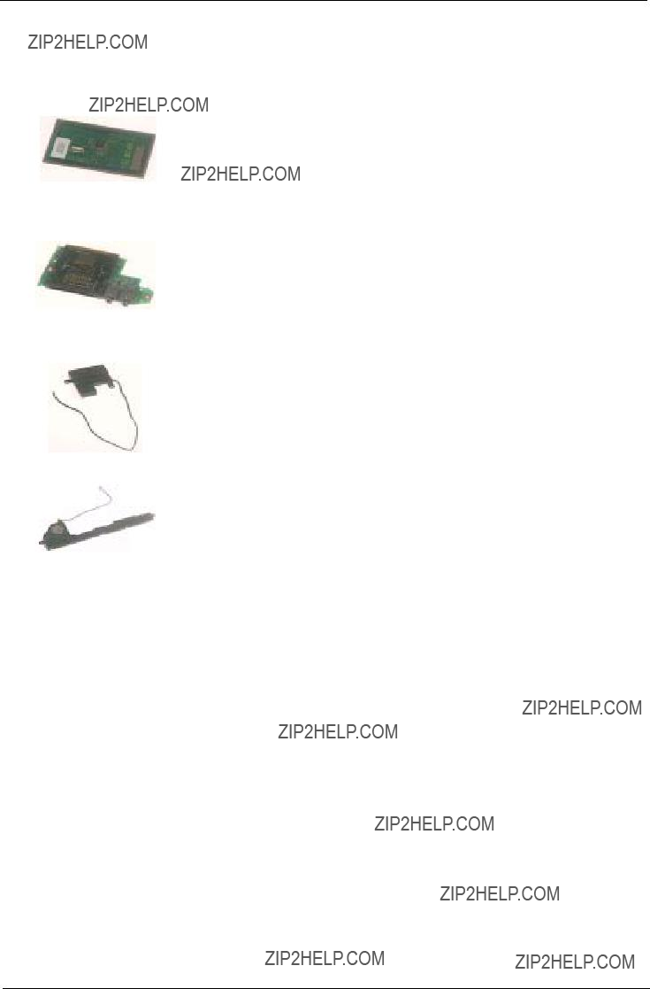
FRU (Field Replaceable Unit) List
This chapter gives you the FRU (Field Replaceable Unit) listing in global configurations of Aspire 2000. Refer to this chapter whenever ordering for parts to repair or for RMA (Return Merchandise Authorization). Please also note that there are some common parts for Aspire 2000, yet the LCD modules are different
in two model.
Please note that WHEN ORDERING FRU PARTS, you should check the most
NOTE: To scrap or to return the defective parts, you should follow the local government ordinance or regulations on how to dispose it properly, or follow the rules set by your regional Acer office on how to return it.
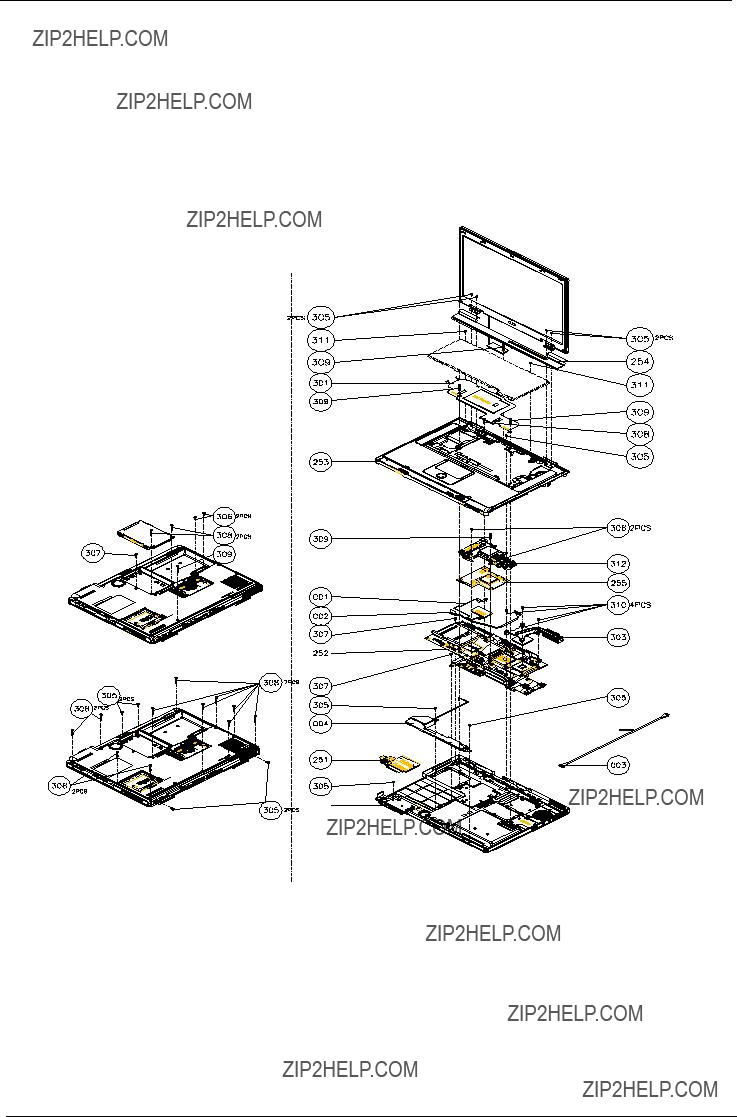
Exploded Diagram


LCD


Appendix A
Model Definition and Configuration
Aspire 2000 series

Appendix B
Test Compatible Components
This computer???s compatibility is tested and verified by Acer???s internal testing department. All of its system functions are tested under Windows XP Home environment.
Refer to the following lists for components, adapter cards, and peripherals which have passed these tests. Regarding configuration, combination and test procedures, please refer to the Aspire 2000 Compatibility Test. Report released by the Acer Mobile System Testing Department.

Microsoft Windows XP (Home) Environment Test


Appendix C
Online Support Information
This section describes online technical support services available to help you repair your Acer Systems. If you are a distributor, dealer, ASP or TPM, please refer your technical queries to your local Acer branch
office. Acer Branch Offices and Regional Business Units may access our website. However some information sources will require a user i.d. and password. These can be obtained directly from Acer CSD Taiwan.
Acer's Website offers you convenient and valuable support resources whenever you need them.
In the Technical Information section you can download information on all of Acer's Notebook, Desktop and Server models including:
!Service guides for all models
!User's manuals
!Training materials
!Bios updates
!Software utilities
!Spare parts lists
!TABs (Technical Announcement Bulletin)
For these purposes, we have included an Acrobat File to facilitate the
Also contained on this website are:
!Detailed information on Acer's International Traveler's Warranty (ITW)
!An overview of all the support services we offer, accompanied by a list of telephone, fax and email contacts for all your technical queries.
We are always looking for ways to optimize and improve our services, so if you have any suggestions or comments, please do not hesitate to communicate these to us.