AT&T
Issue 4
October 1992
AUDIX??
Networking
AT&T
Issue 4
October 1992
AUDIX??
Networking
Copyright ?? 1992 AT&T
All Rights Reserved
Printed in U.S.A.
Notice
While reasonable efforts were made to ensure that the information in this document was complete and accurate at the time of printing, AT&T can assume no responsibility for any errors. Changes and corrections to the information contained in this document may be incorporated into future reissues.
Your Responsibility for Your System's Security
You are responsible for the security of your system. AT&T does not warrant that this product is immune from or will prevent unauthorized use of
Federal Communications Commission Statement Part 15: Class A Statement. This equipment has been tested and found to comply with the limits for a Class A digital device, pursuant to Part 15 of the FCC Rules. These limits are designed to provide reasonable protection against harmful interference when the equipment is operated in a commercial environment. This equipment generates, uses, and can radiate
Part 68: Network Registration Number. This equipment is registered with the FCC in accordance with Part 68 of the FCC Rules. It is identified by FCC registration number
Trademarks
DEFINITY?? is a registered trademark of AT&T.
AUDIX?? is a registered trademark of AT&T.
Refer to the Trademarks and Service Marks section near the front of this manual for additional trademarks.
Ordering Information
The ordering number for this document is
Customer Information Center at
Systems Publications Catalog
Comments
To comment on this document, return the comment card at the front of the document.
Acknowledgment
This document was prepared by the BCSystems Product Documentation Development Department in Denver, CO.
Contents
________________________________________________________________________
iii
iv Contents
________________________________________________________________________________________________
________________________________________________________________________________________________
Contents v
_______________________________________________________________________________________
_______________________________________________________________________________________
5. DCP Mode 2 Networks ??? Modem Pooling . . . . .
CONSIDERATIONS . . . . . . . . . . . . . . .
GENERAL INFORMATION . . . . . . . . . . . .
AUDIX SYSTEM REQUIREMENTS FOR DCP MODE 2 . . .
SWITCH (OR CUSTOMER) REQUIREMENTS FOR DCP MODE 2 . . . . . . . . . . . . . . . . . . . . .
Basic Switch Needs . . . . . . . . . . . . .
DCP Interface for the AUDIX Network Channels . . . .
DCP Interface for the Digital Side of the Modem Pool . .
Analog (Tip and Ring) Interface to the Interlocation Facilities Analog Interface for the Analog Side of the Modem Pool .
Modems and Data Modules . . . . . . . . . . .
Cabling . . . . . . . . . . . . . . . . . .
DATA RATES FOR DCP MODE 2 . . . . . . . . . .
DCP MODE 2 FOR A 5ESS SWITCH . . . . . . . . .
CONSIDERATIONS . . . . . . . . . . . . . . .
GENERAL INFORMATION . . . . . . . . . . . .
AUDIX SYSTEM REQUIREMENTS FOR DCP MODE 3 . . .
SWITCH (OR CUSTOMER) REQUIREMENTS FOR DCP MODE 3 . . . . . . . . . . . . . . . . . . . . .
Colocated Requirements . . . . . . . . . . . .
Interlocation Requirements . . . . . . . . . . .
vi Contents
________________________________________________________________________________________________
________________________________________________________________________________________________
Contents vii
_______________________________________________________________________________________
_______________________________________________________________________________________
viii Contents
________________________________________________________________________________________________
________________________________________________________________________________________________
Contents ix
_______________________________________________________________________________________
_______________________________________________________________________________________
Abbreviations . . . . . . . . . . . . . . . . . . . . . . .
Glossary . . . . . . . . . . . . . . . . . . . . . . . . .
x Contents
________________________________________________________________________________________________
________________________________________________________________________________________________
Contents xi
_______________________________________________________________________________________
_______________________________________________________________________________________
xii Contents
________________________________________________________________________________________________
________________________________________________________________________________________________
Contents xiii
_______________________________________________________________________________________
_______________________________________________________________________________________
xiv Contents
________________________________________________________________________________________________
________________________________________________________________________________________________
Contents xv
_______________________________________________________________________________________
_______________________________________________________________________________________
xvi Contents
________________________________________________________________________________________________
________________________________________________________________________________________________
About This Document
_______________________________________________________________________________________
_______________________________________________________________________________________
This document describes most major aspects of networking AUDIX?? Voice Messaging Systems. Its purpose is to assist any group or person involved with the implementation of an AUDIX network. If it does not contain the information you desire, please ???ll out the feedback form with your comments and send it to the originating organization.
INTENDED AUDIENCE
This document is intended for account teams, the Business Communications Systems Design Center (BCSDC), the Technical Service Center (TSC), the Sales and Technical Response Center (STRC), ???eld technicians, and hotline personnel.
PREREQUISITE SKILLS OR KNOWLEDGE
No prerequisite skills or knowledge are presumed. However, it is recommended that someone with networking experience be available to assist anyone that is new to this type of implementation.
HOW THIS DOCUMENT IS ORGANIZED
Information in this document is organized as follows.
???Chapter 1, Introduction, describes the network interfaces, an overview of how a network is implemented, and the AUDIX system requirements that pertain to any type of AUDIX network.
???Chapter 2, Dedicated EIA
???Chapter 3, Switched EIA
???Chapter 4, DCP Mode 1 Networks ??? 56 Kbps, provides examples and requirements when using AT&T???s DCP Mode 1 for interlocation data transmission.
???Chapter 5, DCP Mode 2 Networks ??? Modem Pooling, provides examples and requirements when using AT&T???s DCP Mode 2 for interlocation data transmission.
???Chapter 6, DCP Mode 3 Networks ??? 64 Kbps, provides examples and requirements when using AT&T???s DCP Mode 3 for colocated or interlocation data transmission.
xvii
xviii About This Document
________________________________________________________________________________________________
________________________________________________________________________________________________
???Chapter 7, Mixtures of
???Chapter 8, EIA
???Chapter 9, DCP Cabling and Administration, explains how to install and administer the DCP interface on the switch for the AUDIX system.
???Chapter 10, DCP Mode 1 Installation and Administration, brie???y describes the requirements of a switch that uses DCP Mode 1 (56 Kbps) communication between adjuncts.
???Chapter 11, DCP Mode 2 Installation and Administration, explains how to install and administer modem pooling for a switch that uses DCP Mode 2 communication between adjuncts. Both
???Chapter 12, DCP Mode 3 Installation and Administration, brie???y explains how to install and administer a DCP Mode 3 (64 Kbps) interface at the switch.
???Chapter 13, AUDIX System Administration, contains procedures for administering the AUDIX systems for networking. It also contains an administrator???s worksheet to help keep track of network parameters.
???Chapter 14, AUDIX Network Testing, contains procedures for testing the network links, for testing transmission between AUDIX systems, and for testing the Remote Updates feature of the AUDIX system.
???Appendix A, Network Considerations, is written for the BCSDC. Every AUDIX network order must pass through the engineering center for design and approval. Information pertains to AUDIX system requirements, trunking between the switches if the network is a remote network, and administrative requirements that must be passed on to the SIM.
???Appendix B, Sales Engineering Notes, is designed to help the branch of???ce implement an AUDIX network.
???Appendix C, AMIS Analog Networking, contains a brief description of the AMIS Analog Networking feature which is an alternative to digital networking.
This document also includes an abbreviations section, glossary, and index.
CHANGES FROM THE PREVIOUS ISSUE
The entire document has been updated to re???ect AUDIX R1V7 enhancements. Speci???c changes include:
???Network
???The automatic network connection turnaround capability and the option to send messages to non- administered recipients has been added (this is administered on the system : translation : machine : audix/amis/call delivery form).
This document has also been updated to re???ect AUDIX setups with DEFINITY Communications System Generic 3 where appropriate.

_______________________________________________________________________________________
_______________________________________________________________________________________
NOTE
In this document, the terms Generic 3i and Generic 3s refer to versions of software based on DEFINITY Generic 1 features. The term Generic 3r refers to the version of software based on DEFINITY Generic 2 features. The term Generic 3 refers to all versions of Generic 3 software (Generic 3i, Generic 3r, and Generic 3s).
CONVENTIONS USED IN THIS DOCUMENT
The following typographic conventions are used in this document:
???Information that appears on your terminal screen ??? including displays, ???eld names, prompts, and error messages ??? is shown in
In the machine name ???eld, type audix.
???Terminal keys that you press are shown in
Press ENTER .
???Two or three keys that you are to press at the same time (that is, you are to hold down the ???rst key while pressing the second key and, if appropriate, the third key as well) are enclosed together, separated
by hyphens, in a
Press
???Variables for which you or the system substitute a word speci???c to your own application are shown in italic type. For example, an error message that appears on the screen with the name of your own speci???c ???lename might appear generically in this document as:
Your ???le <???lename> is formatted incorrectly.
TRADEMARKS AND SERVICE MARKS
The following trademarked products are mentioned in this document:
???5ESS?? Switch is a registered trademark of AT&T
???AUDIX?? System is a registered trademark of AT&T
???DATAPHONE?? is a registered trademark and service mark of AT&T
???DEFINITY?? Communications System is a registered trademark of AT&T
???DIMENSION?? PBX is a registered trademark of AT&T
xx About This Document
________________________________________________________________________________________________
________________________________________________________________________________________________
???ESS??? Switch is a trademark of AT&T
???Hayes?? is a registered trademark of Hayes Microcomputer Products, Inc.
???Manager??? II, Manager??? III, and Manager??? IV are trademarks of AT&T
???MERLIN?? II Communications System is a registered trademark of AT&T
???RICOH??? is a trademark of RICOH Corporation
???Telebit?? is a registered trademark of Telebit Corporation
???TELETYPE?? is a registered trademark of AT&T
RELATED RESOURCES
The following documents may be helpful when planning, ordering, installing, maintaining, and using the AUDIX network.
???AUDIX System Description
???Switch Administration Guide for AUDIX Voice Messaging
???AUDIX Administration
???AUDIX Release 1 Version 7 Forms Reference
???AUDIX Data Acquisition Package
???AUDIX Maintenance for Tier I
HOW TO MAKE COMMENTS ABOUT THIS DOCUMENT
The reader comment card is at the back of this document. While we have tried to make this document ???t your needs, we are interested in your suggestions for improving it and urge you to complete and return a reader comment card.
If the reader comment card has been removed from this document, please send your comments to:
AT&T Technical Publications Department
Room
11900 North Pecos Street
Denver, Colorado 80234
1. Introduction
_______________________________________________________________________________________
_______________________________________________________________________________________
AUDIX Networking enables an organization to transmit messages between two or more AUDIX systems, making the group of systems appear as one large system.
When considering adding more than one system to a single switch, keep in mind that although several systems can be networked at a single location, the systems may or may not be able to be installed as fully integrated AUDIX systems (that is, with a data link installed between the AUDIX system and the switch). The number of directly connected AUDIX adjuncts depends on the switch:
???System 75 and DEFINITY Communications System Generic 1, Generic 3i, and Generic 3s support one directly connected AUDIX system.
???System 85 R2V2 and R2V3 support up to four AUDIX adjuncts.
???System 85 R2V4 and DEFINITY Generic 2 and Generic 3r support up to eight AUDIX adjuncts.
Any additional AUDIX systems must be installed as
THE NETWORK INTERFACE
An AUDIX system provides three types of network connections, using either the Electronic Industries Association (EIA)
???Dedicated
???Switched
Special Application: The

________________________________________________________________________________________________
________________________________________________________________________________________________
NOTE
Although a total of six network channels are available on an AUDIX system, the AUDIX R1V3, R1V4, and R1V5 software limit the number of simultaneously active channels to four. To use all six channels simultaneously, an AUDIX system must have R1V6 or later software and a vintage 7 TN539 or a TN539B ACCE.
???Switched DCP: AUDIX systems communicate through
NOTE
If the customer???s switch does not support the DCP interface, an AT&T DCP switch can be used to provide this interface. For local networking, this is usually done with a MERLIN?? II Communications System. (Remote networking with MERLIN II is not supported.)
The TN539 or TN539B ACCE circuit pack provides two
LOCAL NETWORKING
In a local network setup, one or more AUDIX systems work with a single switch. The local system can be networked with up to 100 other remote AUDIX adjuncts. In this setup, the local system is the one to which the administration terminal the system administrator is using is connected; all other systems are considered remote. All AUDIX subscribers can be assigned the same (or no) pre???xes and separate extension numbers, or different pre???xes to distinguish among local systems.
A
Introduction
_______________________________________________________________________________________
_______________________________________________________________________________________
REMOTE NETWORKING
In a remote network, AUDIX systems are integrated with more than one switch. The local system can be networked with up to 100 other remote AUDIX adjuncts. The local system is the one to which the administration terminal the system administrator is using is connected; all other systems are considered remote. These remote systems may be geographically distant, have different dial plans, and use different connections such as:
???Digital Service (DS1) facilities between switches
???
Any remote network can be mixed with a local network. Switches can use any public or private switched networking facility, or be a part of a Digital Communications System (DCS) network.
NETWORK PLANNING
Planning is an essential ???rst step in setting up an AUDIX network. Network administration should not be started until the local AUDIX system is running smoothly. Network planning should begin as soon as the customer decides to network their AUDIX systems.
One person (perhaps someone also serving as the administrator of one of the AUDIX machines in the network) must serve as coordinator of the network. The network coordinator must establish and maintain a good line of communication with each of the remote system administrators in order to facilitate necessary cooperation and ???ow of information. Because every AUDIX machine within the network must be administered with information about any other AUDIX machine with which it will be exchanging messages, the network coordinator must be prepared to supply each local AUDIX system administrator with the information.
AUDIX NETWORK IMPLEMENTATION
Each AUDIX system in the network requires the following. Each item is explained in some detail on the following pages:
???Speci???c releases of software.
???AUDIX Communications Controller (ACC) or AUDIX Communications Controller Enhanced (ACCE) circuit pack.
???Speci???c issues of supporting circuit packs.
???Rear connector panel and backplane modi???cations.
???New network cabling used with most types of networks. When unique cabling and equipment are required, they will be pointed out in chapters 2 through 7.
???AUDIX system translations must be added.

________________________________________________________________________________________________
________________________________________________________________________________________________
AUDIX Software
An AUDIX network can consist of a mixture of R1V3, R1V4, R1V5, R1V6, and R1V7 systems. If desired, you may upgrade your
NOTE
If the network contains R1V3 or R1V4 systems, the Sending Restrictions feature cannot be used.
ACC/ACCE
The AUDIX Communications Controller (ACC) or AUDIX Communications Controller Enhanced (ACCE) is the circuit pack that provides the interconnections for AUDIX networking. It must be installed in slot 03 of a one- or
This section describes the ACC or ACCE circuit packs currently in existence. All new AUDIX systems ordered with networking are shipped with the latest circuit pack available, currently the TN539B AUDIX Communications Controller Enhanced (ACCE). However, a new AUDIX system can be added to an existing network where the earlier TN366, TN366B, or TN539 circuit packs are used.
TN366 ACC
This circuit pack provides four DCP channels. It must be a TN366 vintage 5 or later. This circuit pack is no longer orderable, but if the customer has an older vintage and wishes to upgrade, this circuit pack is available through QPPCN 330DR (comcode 103279840). It will work with R1V3 and later software.
TN366B ACC
This circuit pack provides four DCP channels. It will work with R1V3 or later software. This circuit pack is no longer orderable (comcode 106186588).
The TN366B is a TN366 that has been enhanced for the following reasons:
???The TN366B will work with modem pools that use 7400A DSUs; the original TN366 will not.
???The TN366B will work with the MERLIN II Communications System which is used as a DCP interface for
???When a Generic 2 universal module serves as the host switch, the TN366B allows access to all four DCP channels; the TN366 does not.

Introduction
_______________________________________________________________________________________
_______________________________________________________________________________________
TN539 ACCE
This circuit pack provides four DCP channels and two
???
???DCP Mode 1 (56 Kbps) interface
???
NOTE
Customers who implemented 56 Kbps networking using TN539 ACCE boards may wish to upgrade to the TN539B ACCE in order to take advantage of the performance improvements and
TN539B ACCE
This pack replaces the TN366, TN366B, or TN539 circuit pack (comcode 106757768). It provides all the functionality of the previous networking boards as well as 56 and 64 Kbps loopback testing capabilities.
All new systems ship with a TN539B ACCE. In addition, you may wish to upgrade an earlier board to a TN539B ACCE for the following reasons:
???You have a TN366 or TN366B ACC and you wish to use the two
???You have a TN366 or TN366B ACC and you wish to obtain the additional activity status information available on the maintenance : network form in R1V7 (for example, if you are using the R1V7 network turnaround feature).
???You have a TN366 or TN366B ACC or a TN539 ACCE and you wish to upgrade to a TN539B ACCE for performance reasons. A TN539B is required at both the sending and receiving machine in order to achieve increased performance.
???You have a TN539 ACCE running DCP Mode 1 (56 Kbps) connections and you wish to replace it with the TN539B in order to take advantage of the AUDIX R1V7
All TN539B ACCE orders (new or upgrade) include two
________________________________________________________________________________________________
________________________________________________________________________________________________
Other AUDIX Circuit Pack Requirements
Certain circuit packs must be present and certain other packs must be of a speci???c vintage or issue.
In slot 01 of the base cabinet the AUDIX system must have the following:
??? TN506B circuit pack (comcode 105222301).
In slot 04 of the base cabinet the AUDIX system must have the following:
???TN472C vintage 2 (white wire
In slot 06 of the base cabinet the AUDIX system must have the following:
???UN160B vintage 2 or later circuit pack (comcode 105319818). This is the Data Base Processor Interface (DBPI).
AUDIX Large System
In slot 01 of the DBP carrier (J58888K) the AUDIX system must have the following:
??? TN506B circuit pack (comcode 105222301).
In slots
??? TN508 (vintage 4 or higher); up to seven packs.
In slot 08 of the DBP carrier the AUDIX system must have the following:
??? TN509C circuit pack (comcode 105319286). This circuit pack is available through QPPCN 444DR.
In slot 10 of the control carrier (J58888H) the AUDIX system must have the following:
??? UN160B circuit pack (comcode 105319818).
In slot 08 of the power carrier (J58888L) the AUDIX system must have the following:
??? 495JB power converter (comcode 104016746).
Rear Connector Panel and Backplane
The network cabling requires a connector on the back of the AUDIX system cabinet. This connector must be attached to the backplane. Certain versions of the backplane require wire modi???cation.

Introduction
_______________________________________________________________________________________
_______________________________________________________________________________________
For new orders, an ACC/ACCE port will be installed at the back of the AUDIX system base cabinet and wired to the backplane.
For upgrades to existing systems, check the base cabinet for an ACC D05 connector. This is a
Rear Connector Panel and Backplane (Large)
Check the control cabinet for an ACC D06 connector. This is a
???If the connector is missing, order the AUDIX Large Networking Upgrade kits D181757 (comcode 105308696) and D182422 (comcode 845798131).
???If the port is installed, check the label on the cable that goes from the connector to the backplane. It will probably be an
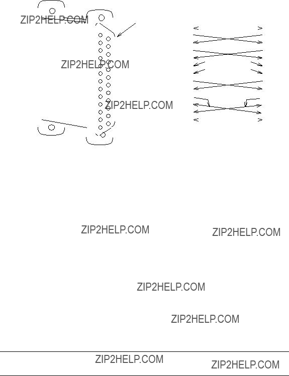
Network Cabling Common to Most Con???gurations
New AUDIX systems ordered with networking will be shipped two
Systems that already have networking installed may have the
The special
The
NOTE
________________________________________________________________________________________________
________________________________________________________________________________________________
Figure
All new AUDIX networking systems are shipped with one
The female Amphenol connector provides access to the four DCP channels (AUDIX networking channels 1, 2, 3, and 4). The
Introduction
_______________________________________________________________________________________
_______________________________________________________________________________________
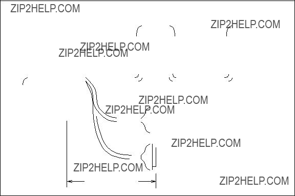
B
MALE CONNECTORS
5.0 FT (1.524 M)
Figure
The
The
The

________________________________________________________________________________________________
________________________________________________________________________________________________
451A ADAPTERS,
F/F (COMES WITH THE
CABLE)
PATCH TO DCP
3.0 FT
INTERFACE AT
(0.914 M)
THE CROSS-
CONNECT FIELD
MODULAR
103A ADAPTERS,
AMPHENOL
MALE CONNECTORS
MALE CONNECTOR
A
CONNECT TO DEDICATED
OR SWITCHED
ENDPOINTS
 B
B
MALE CONNECTORS
5.0 FT (1.524 M)
Figure
Introduction
_______________________________________________________________________________________
_______________________________________________________________________________________
AUDIX System Administration
In order for the AUDIX system to recognize messages addressed to subscribers at other AUDIX systems, it must be administered with remote machine and remote subscriber pro???les. Dial strings, transmission intervals, connection types, and so forth must also be assigned. Each AUDIX system in the network requires this administration of each of the other systems. See Chapter 13, AUDIX System Administration.
NETWORKING ENHANCEMENTS
The AUDIX Networking feature was enhanced for R1V5, R1V6, and R1V7.
R1V5 Release
Major changes brought about by AUDIX R1V5 software and the TN539 ACCE circuit pack:
???
???DCP Mode 1 access to a switched 56 network (that is, 56 Kbps digital transmission) is supported. The AUDIX system must be running R1V5 or later software (56 Kbps
???
???The TN539 ACCE circuit pack can be used with R1V3 and R1V4 AUDIX software, but the
???The TN366 or TN366B circuit pack can be used with R1V5 or later software, but the
???A network can consist of a mixture of R1V3, R1V4, R1V5, R1V6, and R1V7 AUDIX systems. However, the Sending Restrictions feature cannot be used anywhere in a network with R1V3 or R1V4 AUDIX systems.
???Network address ranges ??? up to 16 AUDIX systems can have the same range speci???ed. The old limit (R1V3 and R1V4) is eight.

________________________________________________________________________________________________
________________________________________________________________________________________________
R1V6 Release
Major changes brought about by AUDIX R1V6 software and the vintage 7 TN539:
???With the R1V3, R1V4, and R1V5 software releases, only four channels could be simultaneously active. AUDIX systems with R1V6 software and a vintage 7 TN539 or TN539B ACCE can use all six networking ports simultaneously (however, System 75, Generic 1, Generic 3, and MERLIN II can still only access two of the four DCP channels).
NOTE
If a customer is upgrading to R1V5 or R1V6 from an existing network, and the
R1V7 Release
Major changes brought about by AUDIX R1V7 software and the TN539B board:
???The new TN539B ACCE board can provide faster throughput than previous networking boards for networks with heavy traf???c.
???The R1V7 software and the TN539B ACCE board permit 56 or 64 Kbps loopback testing; the serving of???ce can send data to an AUDIX port and, if the connection is up, the AUDIX system will echo the data back to the serving of???ce. See Chapter 14, AUDIX Network Testing for details.
???On R1V7 systems, the network turnaround feature can be administered. This option is activated using
the system : translation : machine : audix/amis/call delivery form; it can
be administered on a
???If network connection turnaround is implemented, the local machine will call a remote machine and do the following: notify the remote system of its updated subscriber information, request updated subscriber information from the remote system, and send voice mail and updated message status information to the remote system. Then network connection will then be turned around and the remaining events will occur: the remote system will request updated subscriber information from the local system, notify the local system of its updated subscriber information, and send voice mail and updated message status information to the local system.
???If the network turnaround feature is not implemented, the local machine will call a remote machine and do the following: notify the remote system of its updated subscriber information, request updated subscriber information from the remote system, and send voice mail and updated message status information to the remote system. The call will then be disconnected.
The network turnaround feature reduces system overhead time and

2. Dedicated EIA
_______________________________________________________________________________________
_______________________________________________________________________________________
AUDIX networking can be implemented using a dedicated Electronic Industries Association (EIA)
Mixtures of
If your customer develops their own method, contact the Business Communications Systems Design Center (BCSDC) to make sure the method is feasible. Each of the con???gurations presented here is accompanied by the equipment required for the AUDIX systems.
NOTE
System 75, DEFINITY Generic 1, Generic 3, and MERLIN II can access only two of the four DCP channels. This is a limitation regardless of the AUDIX software used and the networking circuit pack provided. When mixing the two DCP channels with the two
AUDIX R1V3, R1V4, and R1V5 software limit the number of simultaneously active channels to four. To use all six channels simultaneously, an AUDIX system must have R1V6 or later software and a TN539 vintage 7 or TN539B ACCE.
CONSIDERATIONS
If a customer is considering using dedicated
???Only local networking con???gurations are supported.
???A maximum of three AUDIX systems can be networked via this method.
???AUDIX software must be R1V5 or later.
???The customer needs a TN539 or TN539B networking board.
???This type of network can operate at speeds up to 64 Kbps (depending on distance).
GENERAL INFORMATION
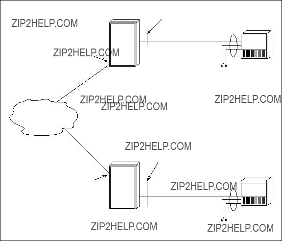
Figure

________________________________________________________________________________________________
________________________________________________________________________________________________
to the channel will retry automatically.
Normally both
If another system must be added to Figure
NOTE
Text Services and/or Call Detail Recording can be added using the DCP channels. See Chapter 4, DCP Mode 1 Networks ??? 56 Kbps, and Chapter 7, Mixtures of
When there are more systems and/or PCs than channels, contention for the channels may occur. This situation can usually be avoided, however, by scheduling the transfer of data at different times of the day. See Chapter 13, AUDIX System Administration for details on how to set up transmission schedules. Even when contention does occur, an AUDIX system will try to establish a connection two more times. If still unable to make the connection, the AUDIX system will try again at the next scheduled interval or when the transmission queue becomes full.
Figure

_______________________________________________________________________________________
_______________________________________________________________________________________
Figure
GROUP 1 (TWO SHOWN)
GROUP 1
Figure

________________________________________________________________________________________________
________________________________________________________________________________________________
Figure
AUDIX REQUIREMENTS FOR DEDICATED
Each AUDIX system must be running R1V5 or later software. Each AUDIX must be equipped with a TN539 or TN539B ACCE circuit pack. The AUDIX Networking Breakout cable
Standard
NOTE

_______________________________________________________________________________________
_______________________________________________________________________________________
SWITCH (OR CUSTOMER) REQUIREMENTS FOR DEDICATED
If the distance between systems is greater than 10 feet (3.05 meters), an M25A
If the distance between AUDIX systems is greater than 50 feet, you can do one of two things:
???In addition to the
Check the document(s) shipped with the data sets for the maximum distances allowed.
???The dedicated connection can be recabled as a switched connection. See Chapter 3, Switched EIA
DATA RATES FOR DEDICATED
Data rate limitations are imposed on the
???At 20 feet (6.1 meters) or less, the data rate can be as high as 64 Kbps.
???At 20 to 50 feet (6.1 to 15.25 meters), the maximum data rate is 19.2 Kbps unless
???At more than 50 feet (15.25 meters),
Con???gurations with
NOTE

________________________________________________________________________________________________
________________________________________________________________________________________________
Figure

3. Switched EIA
_______________________________________________________________________________________
_______________________________________________________________________________________
AUDIX networks can be implemented using a switched Electronic Industries Association (EIA)
If your customer develops their own method, contact the Business Communications Systems Design Center (BCSDC) to make sure the method is feasible. Each of the examples presented here is accompanied by the equipment required for the AUDIX systems and for the switches the AUDIX systems serve.
CONSIDERATIONS
If a customer is considering using switched
???Local or remote networking con???gurations are supported.
???Two or more AUDIX systems can be networked via this method.
???AUDIX software must be R1V5 or later.
???The customer needs a TN539 or TN539B networking board.
???In this type of network speeds can be up to 19.2 Kbps; speeds are limited by the modems or data modules the customer chooses to use.
???The customer will need data modules or
NOTE
System 75, DEFINITY Generic 1 and Generic 3, and MERLIN II can only access two of the four AUDIX DCP channels. This is a limitation regardless of the AUDIX software used and the networking circuit pack provided. Thus, conversion of the
For a System 85 or Generic 2, AUDIX R1V3, R1V4, and R1V5 software limit the number of simultaneously active channels to four. To use all six channels simultaneously with a System 85 or Generic 2, an AUDIX system must have R1V6 or later software and a TN539 vintage 7 or TN539B ACCE.
________________________________________________________________________________________________
________________________________________________________________________________________________
SWITCHED
When a dedicated
Figure
If the network requires switched access to all
Switched
Figure
If Call Detail Recording is required, a PC can be included in a switched
_______________________________________________________________________________________
_______________________________________________________________________________________
GROUP 2
SWITCH
GROUP 2
MODEM

 GROUP 1
GROUP 2
AUDIX
MODEM
Figure

________________________________________________________________________________________________
________________________________________________________________________________________________
AUDIX System Requirements For Switched
Each AUDIX system must be running R1V5 or later software. Each AUDIX system must be equipped with a TN539 or TN539B ACCE circuit pack. The AUDIX Networking Breakout cable
T/R
GROUP 2
AUDIX
MODEM
T/R
GROUP 2
AUDIX
MODEM
Figure
Switch (or Customer) Requirements For Switched
Modems
Each switched
???AT&T 2296A
???AT&T Paradyne 3820
???AT&T Paradyne DM424
???MICROCOM QX 3296/C (not orderable through AT&T)

_______________________________________________________________________________________
_______________________________________________________________________________________
NOTE
Equivalent modems such as the AT&T Paradyne DL424 instead of the DM424 modem could be used.
The modem requires a connection through one of the switch???s analog ports or can connect directly to a CO line. Switch analog port circuit packs are:
???System 75, Generic 1, and Generic 3: TN742 or TN746B analog line circuit
???System 85 and Generic 2 traditional module: SN222, SN228, or SN228B analog line circuit
???System 85 and Generic 2 universal module: TN742 or TN746B analog line circuit
ALL CONNECTIONS
GROUP 2
SWITCH
TO ANALOG PORTS
GROUP 1
T/R
GROUP 2
AUDIX
MODEM
T/R
Figure
If the modems must be located greater than 5.0 feet (1.524 meters) from the AUDIX system, an M25A RS- 232 extender cable is required for each. The modem must be within 50 feet (15.24 meters) of the AUDIX system. The tip/ring circuit should be engineered by a switch representative.

________________________________________________________________________________________________
________________________________________________________________________________________________
Data Rates for Switched
When connected through the switch, data rates are limited to speeds up to and including 19.2 Kbps. The speeds may be reduced by the limit of the modems and the public/private facilities involved.
Figure

_______________________________________________________________________________________
_______________________________________________________________________________________
SWITCHED
By using a data module instead of a modem, the
???To convert to DCP mode 1 (56 Kbps) or DCP mode 3 (64 Kbps), use a Modular Processor Data Module, Model M1* (MPDM/M1*). In either of these cases, the channels can only be used for incoming calls; they cannot be used for outgoing calls. All outgoing calls must use the DCP ports.
???To convert to DCP mode 2, use a 7400A or 7400B Data Service Unit (DSU). In this case, the channels can be used for incoming or outgoing calls.
Converting
Mixtures of
Sys 75,
G1, or
G3
Public/Private
Interlocation
Facilities
NOTE: The 7400A and 7400B data modules are
the MPDM/M1* is for incoming calls only.
Figure
________________________________________________________________________________________________
________________________________________________________________________________________________
AUDIX System Requirements for Switched
Each AUDIX system must be running R1V5 or later software and must be equipped with a TN539 or TN539B ACCE circuit pack and the AUDIX Networking Breakout cable
Switch (or Customer) Requirements for Switched
Each AUDIX
???One of the following data modules:
???For DCP mode 1 (56 Kbps, synchronous) or DCP mode 3 (64 Kbps, synchronous) use an MPDM/M1*. The MPDM/M1* operates in synchronous mode. An older MPDM can be upgraded to support 56 Kbps with
???For DCP mode 2, use a 7400A or 7400B DSU. The 7400A and 7400B operate in only asynchronous mode. These channels can be used for incoming or outgoing calls.
???One
???Switch DCP interface:
???System 75, Generic 1, and Generic 3: TN754 Digital Line Circuit
???System 85 and Generic 2 traditional module: SN270B General Purpose Port
???System 85 and Generic 2 universal module: TN754
If the converted channels are to be used for DCP Mode 2 operation, two modem pool pairs are also required. See Chapter 5, DCP Mode 2 Networks ??? Modem Pooling. Access to two additional channels on the interlocation facilities might also be required.
Data Rates for Switched
Data rates are limited to the capabilities of the data modules. MPDM/M1* data modules operate at 56 or 64 Kbps (synchronous), but they do not support dialing out at these speeds, so the converted channels would be limited to receiving calls only. In some cases this limitation would not create a problem. In cases where it would, the 7400A data module, which supports incoming and outgoing calls, can be used. However, with the 7400A, communication is performed at low speeds (up to and including 19.2 Kbps, asynchronous).

4. DCP Mode 1 Networks ??? 56 Kbps
_______________________________________________________________________________________
_______________________________________________________________________________________
AUDIX networks can be implemented using AT&T???s Digital Communications Protocol (DCP) Mode 1. This type of network is only used when the AUDIX systems to be networked are not colocated and, therefore, they require some type of interlocation facility to pass data. (For local networking, see Chapter 6, DCP Mode 3 Networks ??? 64 Kbps.) This chapter presents supported 56 Kbps con???gurations; all other 56 Kbps con???gurations must be designed by Custom Development.
The examples show an AUDIX system using DCP at both ends. See Chapter 7, Mixtures of
NOTE
Customers who implemented 56 Kbps networking using TN539 ACCE boards may wish to upgrade to AUDIX R1V7 software and a TN539B ACCE in order to take advantage of the performance improvements and
CONSIDERATIONS
If a customer is considering using DCP Mode 1 connections in their AUDIX network, keep the following in mind:
???Only remote networking con???gurations are supported.
???Two or more AUDIX systems can be networked via this method.
???AUDIX software must be R1V5 or later. However, R1V7 software is recommended because of the networking feature enhancements and 56 Kbps loopback testing capabilities included in that load when a TN539B ACCE board is used.
???AUDIX systems running R1V5 or R1V6 software require an MPDM/M1* for loopback testing. AUDIX R1V7 systems only require an MPDM/M1* if the two
???The customer needs a TN539 or TN539B ACCE networking board; the TN539B is recommended because of the 56 Kbps loopback testing capabilities included in that load when AUDIX R1V7 software is used.
???Transmission in this type of network is
???The customer will need access to 56 Kbps
???The customer will also need a DCP interface on the switch to connect with the AUDIX and a DS1 interface on the switch to connect with the 56 Kbps network.

________________________________________________________________________________________________
________________________________________________________________________________________________
NOTE
MERLIN II, System 75, and DEFINITY Generic 1 and Generic 3 can only access two of the four DCP channels. This is a limitation regardless of the AUDIX software and networking circuit pack used. See Chapter 3, Switched EIA
GENERAL INFORMATION
To use DCP Mode 1 as the transmission protocol, the switch must be set up to access a switched network at 56 Kbps via
Figure
NOTE
If the customer does not subscribe to switched 56 service, check with the DCP Mode 2, DCP Mode 3, and

_______________________________________________________________________________________
_______________________________________________________________________________________
PRESENCE
SWITCH
SWITCHED 56
SERVICE
PRESENCE
SWITCH
FIELD
SWITCH 
AUDIX
DCP
(NOT EQUIPPED)
FIELD
GROUP 2
SWITCH
DCP
AUDIX
(NOT EQUIPPED)
Figure

________________________________________________________________________________________________
________________________________________________________________________________________________
Static Access
Static SDDN
The central of???ce must provide one of the following:
???SDN, T1.5, or DDS and Switched Digital Service (SDS), or compatible service offered by another vendor
???A 4ESS supporting 56 Kbps service
A customer with T1.5 access to a central of???ce tariffed for SDN and T1.5 that does not home to a 4ESS with SDS cannot use this option.
Dynamic Access
Dynamic SDDN
The T1.5 is dedicated to SDN and is therefore not exclusively 56 Kbps. The central of???ce must route to a 4ESS that supports 56 Kbps via digital connectivity. This access may only be offered on circuits without echo cancellation.
The dynamic arrangement is not possible from locations using DDS access. DDS lines must terminate in a central of???ce that has been tariffed for SDN, DDS, and SDS.
System 85 R2V3 and R2V4 do not support dynamic access. System 75 R1V3 and and DEFINITY Generic 1, Generic 2, and Generic 3 do support dynamic access. However, if a customer wants to use a Generic 2 for Switched 56 Kbps networking, contact the BCSDC for help.
NOTE
Dynamic trunk group arrangements cannot be used by modem pooling. If a customer has both 56 Kbps and modem pooling, two trunk groups are required.
_______________________________________________________________________________________
_______________________________________________________________________________________
AUDIX SYSTEM REQUIREMENTS FOR DCP MODE 1
Each AUDIX system requiring access to a switched 56 network must be running R1V5 or later software. Each AUDIX system must also be equipped with a TN539 or TN539B ACCE circuit pack, the AUDIX Networking Breakout cable
AUDIX
ACCESS
Figure

________________________________________________________________________________________________
________________________________________________________________________________________________
SWITCH (OR CUSTOMER) REQUIREMENTS FOR DCP MODE 1
To implement AUDIX networking over static or dynamic switched 56 Kbps facilities, the customer???s switch must have a DCP interface to connect with the AUDIX system and a DS1 interface to connect with the 56 Kbps switched network.
Whether a customer is using static or dynamic 56 Kbps, the
Contact the Business Communications Systems Design Center (BCSDC) to design ISDN.
NOTE
The following equipment is typical for 56 Kbps facility access:
???Digital Line Circuits for the AUDIX network
???DS1 Interface
???For R1V5 or R1V6, a Modular Processor Data Module, Model M1* (MPDM/M1*) ACCUNET data module with V.35 interface card (for loopback testing)
NOTE
See the DEFINITY?? Communications System & System 75/85
Static Access Switch Requirements
The requirements for networking AUDIX systems via static 56 Kbps facilities depend on the customer???s premise switch:
???System 75
???The switch must be R1V3 2.1 or later.
???All tone detectors must be TN748C (V4 or later).
???DEFINITY Generic 1 and Generic 3
???Any release will support static 56 Kbps access.
???All tone detectors must be TN748C (V4 or later).

_______________________________________________________________________________________
_______________________________________________________________________________________
???System 85
???The switch must be R2V3 or R2V4
???All tone detectors must be at least an SN255.
???DEFINITY Generic 2
???Any release will support static 56 Kbps access.
???For universal modules, the detector must be a TN748C (V4 or later). For traditional modules, the detector is a SN255.
Dynamic Access Switch Requirements
The requirements for networking AUDIX systems via dynamic 56 Kbps facilities depend on the customer premise switch:
???System 75
???The switch must be R1V3 2.1 or later.
???All tone detectors must be TN748C (V4 or later).
???DEFINITY Generic 1 and Generic 3
???Any release will support dynamic 56 Kbps access.
???All tone detectors must be TN748C (V4 or later).
???System 85
???Does not support dynamic access.
???DEFINITY Generic 2
???Any release will support dynamic 56 Kbps access.
???For universal modules, the detector must be a TN748C (V4 or later). For traditional modules, the detector is a SN255.
For help in designing dynamic switched 56 Kbps networking with a Generic 2, contact the BCSDC.
NOTE
The MERLIN II does not support this arrangement. If your customer has a
DATA RATES FOR DCP MODE 1
All of the con???gurations shown in this chapter operate at 56 Kbps.
________________________________________________________________________________________________
________________________________________________________________________________________________

5. DCP Mode 2 Networks ??? Modem Pooling
_______________________________________________________________________________________
_______________________________________________________________________________________
AUDIX networks can be implemented using AT&T???s Digital Communications Protocol (DCP) Mode 2. This type of network is only used when the AUDIX systems to be networked are not colocated and, therefore, require some type of interlocation facility to pass data. This arrangement makes use of the switch???s modem pool or can be implemented using
Mixtures of
If a customer develops their own method, contact the Business Communications Systems Design Center (BCSDC) to make sure it is feasible. Each of the examples presented here is accompanied by the equipment required for the AUDIX systems and for the switches that the AUDIX systems serve.
CONSIDERATIONS
If a customer is considering using DCP Mode 2 connections in their AUDIX network, keep the following in mind:
???Only remote networking con???gurations are supported.
???Two or more AUDIX systems can be networked via this method.
???AUDIX software must be R1V3 or later.
???The customer needs a TN366, TN366B, TN539, or TN539B networking board.
???Transmission in this type of network is
???The customer will need
NOTE
System 75 and DEFINITY Generic 1 and Generic 3 can be set up to access only two of the four DCP channels. This is a limitation regardless of the AUDIX software used and the networking circuit pack provided. See Chapter 3, Switched EIA

________________________________________________________________________________________________
________________________________________________________________________________________________
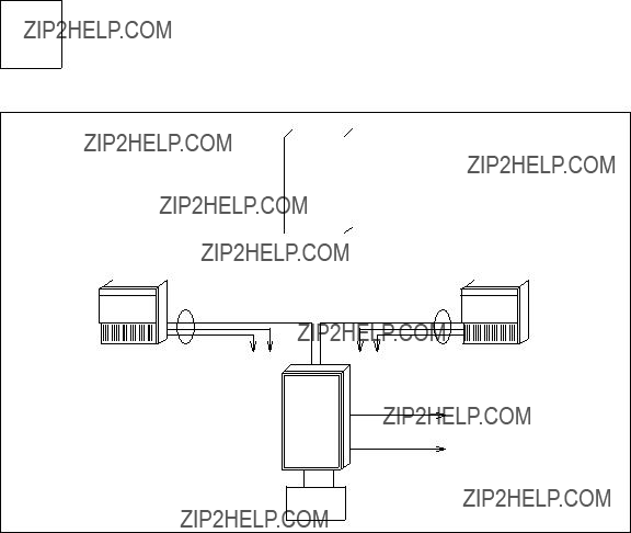
GENERAL INFORMATION
DCP Mode 2 networking uses the DCP interface between the AUDIX system and the switch. Analog or
Figure
105A MOUNTING
WITH 8 MODEMS
77A MOUNTING
WITH 8 DATA SETS
105A MOUNTING
WITH 8 MODEMS
77A MOUNTING
WITH 8 DATA SETS
NOTE: Use 46A2 mounting if MTDMs are used instead of 7400As.
Figure

_______________________________________________________________________________________
_______________________________________________________________________________________
TO THE CROSS-
CONNECT FIELD
Figure
In Figure
Figure

Figure

_______________________________________________________________________________________
_______________________________________________________________________________________
AUDIX SYSTEM REQUIREMENTS FOR DCP MODE 2
Each AUDIX system must be running R1V3 or later software and must be equipped with one of the following:
???TN366 AUDIX Communications Controller (ACC) circuit pack
???TN366B ACC circuit pack
???TN539 ACC Enhanced (ACCE) circuit pack
???TN539B ACCE circuit pack
The AUDIX Networking Breakout cable
SWITCH (OR CUSTOMER) REQUIREMENTS FOR DCP MODE 2
The switch must have a DCP interface and some type of modem pool to provide access to the analog or
???
???
NOTE
It is strongly recommended that all modems in a modem pool be of the same make and model.

________________________________________________________________________________________________
________________________________________________________________________________________________
Basic Switch Needs
The switch must have the following circuit packs to support modem pooling:
???System 75, Generic 1, Generic 2 (universal module), or Generic 3:
???TN748C Tone Detector (System 75 requires a vintage 1 or vintage 3 board; Generic 1 and Generic 3 require vintage 3) ??? required in all carriers of a System 75, but not all carriers of a Generic 1 or Generic 3. (Do not use the TN748B, TN748D vintage 1, or the TN756.) For System 75, Generic 1, and Generic 3, this board does not require assignment, but for Generic 2, it does (use channels 4 and 8).
NOTE
The TN748D vintage 1 board does not currently work for this application. Also, any existing TN748B tone detectors must be upgraded to TN748Cs.
???TN727 Network Controller (System 75) or TN777 Network Controller (Generic 1 and Generic 3) is required.
???MT 771B Maintenance Test Circuit (Generic 2 universal module; equivalent to the SN261).
???System 85 or Generic 2 (traditional module):
???SN253 Auxiliary Tone Plant (one in each module used)
???SN255B or SN255C Tone Detector
???SN261B or SN261C Analog/Digital Facility Test Circuit
DCP Interface for the AUDIX Network Channels
The following digital lines are required to terminate the AUDIX network channels at the switch:
???System 75, Generic 1, or Generic 3:
Two TN754 Digital Line ports are required for the AUDIX DCP channels. Two more ports are required if the AUDIX
???Generic 2 (universal module):
Two TN754 Digital Line ports are required for the AUDIX DCP channels. Two more ports are required if the AUDIX
???System 85 or Generic 2 (traditional module):
Two SN270B General Purpose Port (GPP) ports are required for the AUDIX DCP channels. Two more ports are required if the
_______________________________________________________________________________________
_______________________________________________________________________________________
DCP Interface for the Digital Side of the Modem Pool
The following digital lines are required to terminate the digital side of a modem pool:
???System 75, Generic 1, or Generic 3:
One TN754 or TN754B Digital Line port is required for each modem pool pair. The ports used for the modem pool must appear on a circuit pack(s) separate from the pack(s) used for the AUDIX channels.
???Generic 2 (universal module):
One TN754 or TN754B Digital Line port is required for each modem pool pair.
???System 85 and Generic 2 (traditional module):
One SN270B General Purpose Port is required for each modem pool pair.
Analog (Tip and Ring) Interface to the Interlocation Facilities
One of the following analog trunk circuits is required for terminating interlocation analog facilities at the switch:
???System 75, Generic 1, Generic 2 (universal module), or Generic 3:
???TN747B Central Of???ce (CO) Trunk (1200 to 9600 bps)
???TN753 Direct Inward Dialing (DID) Trunk (1200 to 9600 bps)
???TN760B Tie Trunk (1200 to 9600 bps)
???System 85 or Generic 2 (traditional module):
???SN230B CO Trunk (1200 to 9600 bps)
???SN232B DID Trunk (1200 to 9600 bps)
???SN233C Tie Trunk (1200 to 9600 bps)
Analog Interface for the Analog Side of the Modem Pool
The following analog lines are required to terminate the analog side of the modem pool:
???System 75, Generic 1, Generic 2 (universal module), or Generic 3:
One TN742 or TN746B Analog Line port is required for each modem pool pair.
???System 85 and Generic 2 (traditional module):
One SN243B Analog Data Port is required for each modem pool pair.

________________________________________________________________________________________________
________________________________________________________________________________________________
Modems and Data Modules
The following modems can be used in a modem pool for AUDIX networking. One modem is required for each modem pool pair.
???AT&T 2296A
NOTE
The 2296A must have a 140C1, (V1.1 or V1.2; supported but no longer purchasable) or a 140F1 Memory Module (V1.1) installed in the
???MICROCOM QX 3296/C
???AT&T Paradyne 3820
???AT&T Paradyne DM424
NOTE
Equivalent modems such as the AT&T Paradyne DL424 instead of the DM424 modem could be used.
The following data modules can be used in a modem pool used by AUDIX systems. One data module is required for each modem pool pair.
??? 7400A Data Service Unit
NOTE
The 7400A DSU is con???gured for Data Terminal Equipment (DTE) modem pool operation with
??? MTDM
NOTE
Make certain the MTDM is set up in one of two ways: 1) processor PID ABCED and EPROM PID ABGHB are used, or 2) processor PID ABGHC, no EPROM installed, and IC3 is numbered 8052. In either case, make sure that TRIC 4 chips are used (coded 229EJ). If the MTDM requires an upgrade, order the MTDM
In selecting modems or data modules for modem pooling, it is important to note that once a speci???c model is chosen for use on one end of the remote network, only certain models will work on the other end of the remote connection. Combinations that have been tested are listed in the following tables. Combinations that work are marked as ??????OK,?????? and those that do not work are marked ??????FAIL.??????

_______________________________________________________________________________________
_______________________________________________________________________________________
NOTE 1 ??? ???ow control problem. Both the MTDM and the 7400A expect XON/XOFF ???ow control when running 19.2 Kbps.
NOTE 2 ??? works but not cost effective (RS232 modems should be running 19200 also).
NOTE 3 ??? not tested and not cost effective (modems should be running 19.2). Voice messages can emulate XON/XOFF. This results in lost data and dropped connections.
NOTE 4 ??? not tested because not cost effective (424 not off the shelf compatible with 7400A in a rack mount).
NOTE 5 ??? not recommended since MTDM is being manufacture discontinued.

________________________________________________________________________________________________
________________________________________________________________________________________________
NOTE 1 ??? MTDM is being manufacture discontinued.
NOTE 2 ??? ???ow control problem. Both the MTDM and the 7400A expect XON/XOFF ???ow control when running 19.2 Kbps. Voice messages can emulate XON/XOFF. This results in lost data and dropped connections.
NOTE 3 ??? not tested.
NOTE 4 ??? not tested; expected to fail.
NOTE 5 ??? not tested; expected to work.
NOTE 6 ??? 7400A expects a result code that is not given by the modem. 3296 sends a 32 and the 7400A expects a 12. 3296 sends a 37; 424 sends a 17 for 19200 and the 7400A expects a 14.
_______________________________________________________________________________________
_______________________________________________________________________________________
The following equipment is required when
???
???The 2296A requires a 105A mounting
???One of the following
???The MTDM requires a 46A2 mounting
???The 7400A requires a 77A mounting
Cabling
Cabling for
Cabling for
DATA RATES FOR DCP MODE 2
This arrangement operates at speeds up to and including 9.6 Kbps (the limit for modem pooling).
DCP MODE 2 FOR A 5ESS SWITCH
The System 75, System 85, DEFINITY Generic 1, Generic 2, Generic 3, and DIMENSION PBX systems support the DCP interface. If the customer has an AUDIX system serving another switch and would like to network the AUDIX system with another location, they could use an AT&T digital PBX for its DCP and modem pooling capabilities. A picture of the DCP Mode 2 arrangement is shown along with a DCP Mode 3 arrangement in Chapter 6, DCP Mode 3 Networks ??? 64 Kbps.
________________________________________________________________________________________________
________________________________________________________________________________________________

6. DCP Mode 3 Networks ??? 64 Kbps
_______________________________________________________________________________________
_______________________________________________________________________________________
AUDIX networks can be implemented using AT&T???s Digital Communications Protocol (DCP) Mode 3. This arrangement can be used when the AUDIX systems are colocated (serving the same switch) or when they are at separate customer sites. This chapter presents supported local and remote networking con???gurations. The examples show the AUDIX system using DCP at both ends. See Chapter 7, Mixtures of
If your customer develops their own method, contact the Business Communications Systems Design Center (BCSDC) to make certain it is feasible. Each of the examples presented here is accompanied by the equipment required for the AUDIX systems and for the switches that the AUDIX systems serve.
CONSIDERATIONS
If a customer is considering using DCP Mode 3 connections in their AUDIX network, keep the following in mind:
???Local or remote networking con???gurations are supported.
???Two or more AUDIX systems can be networked via this method.
???AUDIX software must be R1V3 or later. For remote con???gurations, R1V7 software is recommended because of the 64 Kbps loopback testing capabilities included in that load.
???The customer needs a TN366, TN366B, TN539, or TN539B networking board. For remote con???gurations, the TN539B is recommended because of the 64 Kbps loopback testing capabilities included in that board.
???Transmission in this type of network is
???For remote con???gurations, the customer will need access to 64 Kbps public or private telephone network facilities; these should normally be a T1 carrier with DS1 services.
NOTE
System 75, DEFINITY Generic 1 and Generic 3, and MERLIN II can be set up to access only two of the four DCP channels. This is a limitation regardless of the AUDIX software used and the networking circuit pack provided. See Chapter 3, Switched EIA
________________________________________________________________________________________________
________________________________________________________________________________________________
GENERAL INFORMATION
DCP Mode 3 networks use the DCP interface on the AUDIX system and on the switch. Since the AUDIX connections are switched, the AUDIX channels can be shared with the CDR application. For colocated AUDIX systems, communication between AUDIX systems is directly from one switch DCP port to another. Figure
When the AUDIX systems are at different customer locations serving separate switches, interlocation facilities are usually T1 Carrier with a Digital Service 1 (DS1) interface at the switches providing the termination.
AUDIX SYSTEM REQUIREMENTS FOR DCP MODE 3
Each AUDIX system must be running R1V3 or later software and must be equipped with one of the following:
???TN366 AUDIX Communications Controller (ACC) circuit pack
???TN366B ACC circuit pack
???TN539 ACC Enhanced (ACCE) circuit pack
???TN539B ACCE circuit pack
If the AUDIX system is linked to a Generic 2 universal module, the TN366B or TN539 or TN539B must be used if the customer requires all four DCP channels. If a TN366 is used, only channels 1 and 3 can be used. If the AUDIX system is linked to a MERLIN II, the TN366B, TN539, or TN539B must be used.
In addition, for MERLIN II, the following is required:
???MERLIN II control unit (power/processor/base)
???Feature Module II
???Feature Module III
???008D digital station module
???356A adapter (one per AUDIX system), comcode 104158829
???
The AUDIX Networking Breakout cable

_______________________________________________________________________________________
_______________________________________________________________________________________
FIELD
DCP
AUDIX
ACCESS
FIELD
GROUP 2
ACCESS
Figure

________________________________________________________________________________________________
________________________________________________________________________________________________
Figure
SWITCH (OR CUSTOMER) REQUIREMENTS FOR DCP MODE 3
Switch requirements depend on whether the systems are serving the same switch or are serving different switches.
Colocated Requirements
One of the following switches must be used and equipped with a DCP interface for termination of the AUDIX DCP channels:
???System 75, Generic 1, Generic 2 (universal module), or Generic 3:
Two TN754 Digital Line ports are required per AUDIX system. Although not required, it is recommended that the circuits be on separate packs so all four network channels will not be lost in the event a single pack goes bad.
NOTE
All ports on a TN754 should be assigned as either lines (pdm) or trunks (tdm). Trunk ports will have problems when assigned on circuit packs that have other ringing stations (that is, line circuits). Make sure no ports on the pack is assigned as a trunk (TDM) or assigned to a modem pool.
_______________________________________________________________________________________
_______________________________________________________________________________________
???System 85 or Generic 2 (traditional module):
Two SN270B General Purpose Ports are required per AUDIX system. Although not required, it is recommended that the ports be on separate packs. Then not all four network channels will be lost in the event a single pack goes bad.
???MERLIN II (for colocated systems only)
Two ports on an 008D Digital Line card; the MERLIN II must be equipped as speci???ed earlier in this chapter in AUDIX System Requirements for DCP Mode 3.
When the AUDIX
Interlocation Requirements
In addition to the requirements listed in the previous paragraphs, a T1 Carrier (DS1 Interface set for Alternate Voice/Data) or the
The BCSDC will design networks using ISDN.
NOTE
The switch must have the following circuit packs:
???System 75, Generic 1, Generic 2 (universal module), or Generic 3:
???TN748C Tone Detector (System 75 requires a vintage 1 or vintage 3 board; Generic 1 and Generic 3 require vintage 3) ??? required in all carriers of a System 75, but not all carriers of a Generic 1 or Generic 3. (Do not use the TN748B, TN748D vintage 1, or the TN756.) For System 75, Generic 1, and Generic 3, this board does not require assignment, but for Generic 2, it does (use channels 4 and 8).
NOTE
The TN748D vintage 1 board does not currently work for this application. Also, any existing TN748B tone detectors must be upgraded to TN748Cs.
???TN727 Network Controller (System 75) or TN777 Network Controller (Generic 1 and Generic 3) is required.
???MT 771B Maintenance Test Circuit (Generic 2 universal module; equivalent to the SN261).
???System 85 or Generic 2 (traditional module):
???SN253 Auxiliary Tone Plant (one in each module used)
???SN255B or SN255C Tone Detector
???SN261B or SN261C Analog/Digital Facility Test Circuit
________________________________________________________________________________________________
________________________________________________________________________________________________
AUDIX systems could use up to six channels at any one time. Figure
DATA RATES FOR DCP MODE 3
This arrangement operates at speeds of 64 Kbps.
Figure
_______________________________________________________________________________________
_______________________________________________________________________________________
DCP MODE 3 FOR A 5ESS SWITCH
Figure
???Provides a 64 Kbps digital network path between the two AUDIX systems shown.
???Provides a 64 Kbps digital network path to an AUDIX system located outside the 5ESS environment.
???Generic 2 software (R2V5) provides the ability to designate the digital path as the
NOTE
Any network of this nature is considered experimental and should be developed on an individual basis by the BCSDC.
MODEM
POOL
Figure
________________________________________________________________________________________________
________________________________________________________________________________________________

7. Mixtures of
_______________________________________________________________________________________
_______________________________________________________________________________________
This chapter presents supported con???gurations using
CONSIDERATIONS
An AUDIX network can be implemented using both
NOTE
System 75, DEFINITY Generic 1 and Generic 3, and MERLIN II can be set up to access only two of the four DCP channels. This is a limitation regardless of the AUDIX software used and the networking circuit pack provided. See Chapter 3, Switched EIA
Figure
Figure

________________________________________________________________________________________________
________________________________________________________________________________________________
Figure
Figure

_______________________________________________________________________________________
_______________________________________________________________________________________
Public/Private
Interlocation
Facilities
NOTE: The 7400A and 7400B data modules are
the MPDM/MI* is for incoming calls only.
Figure

Figure

Figure
________________________________________________________________________________________________
________________________________________________________________________________________________
8. EIA
_______________________________________________________________________________________
_______________________________________________________________________________________
This chapter shows how to cable the AUDIX
DEDICATED
Figure
Within 50 feet (15.25 meters), the data rate may be up to and including 19.2 Kbps. Within 20 feet (6.1 meters), the data rate may be up to and including 64 Kbps. When data sets are used, check the documentation provided with the data sets for supported data rates.

Figure

Figure

________________________________________________________________________________________________
________________________________________________________________________________________________
CONNECTOR
GREATER THAN 50 FT (15.25 M)
Figure
SWITCHED
Figure

Figure
Figure

________________________________________________________________________________________________
________________________________________________________________________________________________
The modems used for switched
???For an AT&T 2296A, enter the following:
???ATI0 RETURN
ID:961
???ATI1 RETURN
version:243
???ATI2 RETURN
checksum:OK
All 2296A modems must have at least a 140C memory module.
???For an AT&T Paradyne 3820, enter the following:
???ATI0 RETURN
ID:144
???ATI1 RETURN
version:212
???ATI2 RETURN
checksum:OK
???For an AT&T Paradyne DM424, enter the following:
???ATI0 RETURN
ID:960
???ATI1 RETURN
version:0626/0403
???ATI2 RETURN
checksum:0454
???For a MICROCOM QX 3296/C, enter the following:
???ATI0 RETURN
ID:960
???ATI1 RETURN
version:010f1
???ATI2 RETURN
checksum:OK

_______________________________________________________________________________________
_______________________________________________________________________________________
DIP Switch Settings
There are no required DIP switch settings for the 7400A or 7400B data sets. The AT&T Paradyne 3820 has no dip switches.
For other modems supported by AT&T, the dip switches should be set as follows:
???For the AT&T Paradyne DM424 (or DL424), the dip switches in the rear of the modem should all be UP.
???For the AT&T 2296A, the dip switches under the front panel should be set so 6 is UP; 1, 5, 7, and 8 are DOWN.
???For the MICROCOM QX 3296/C, set the switches in one of the following ways:
???For MNP 19.2 Kbps mode, set the switches in the front of the modem so 1, 4, 5, 6, 7, and 9 are UP; 2, 3, and 8 are DOWN. Set the switches in the rear of the modem so 4, 5, and 6 are UP; 1, 2, 3, 7, and 8 are DOWN.
???For
Mixing Modem Types and Modes
The AT&T 2296A modem is not in the following table because the other modems are better alternatives. If you do wish to a 2296A, set it up for
FS ??? modem is in ???xed speed mode. Tested speeds are 19.2K, 9600, and 4800 bps.
MNP ??? tested MNP speeds are 19.2K, 9600, and 4800 bps.
Yes1 ??? all tested cases passed except 3296 (FS @ 4800) to a 424 (FS @ 9600) fails. Calls from the 424 to the 3296 passed.
Yes2 ??? all tested cases passed except 3296 (FS @ 4800) to a 424 (MNP @ 19.2K) fails. Calls from the 424 to the 3296 passed.

________________________________________________________________________________________________
________________________________________________________________________________________________
This type of connection is shown for a DCP switch in Figure
???To convert an
An initialization string for the 7400A or 7400B will have to be entered on the AUDIX system : translation : network port form.
???If a 7400A is used, make sure it is optioned for Data Communications Equipment (DCE). Lift off the cover and check the vertical card at the front. If it reads DCE, the 7400A is okay. If not, remove the card, turn it around, and reinstall it. If a 7400B is used, it does not require this step. It is always optioned for DCE.
To set up the 7400A, go to the front panel and press the next/no button until the set interface options comes up. Then press the yes button and choose INT=AT COMM.
???For a 7400B, set switch 1 to ON if there is no telephone connected to the data module. To get to switch 1, lift the cover off the modem.
???To convert an
NOTE
If you are using an older version of the MPDM, it must be upgraded to an MPDM/M1*. Use
_______________________________________________________________________________________
_______________________________________________________________________________________
Table
SWITCH ADMINISTRATION
The only administration required at the switch is the translation of the new analog or DCP ports for communication with the appropriate endpoints. For analog port translations, see the appropriate switch documentation. For DCP port translations, see Chapter 9, DCP Cabling and Administration.
NOTE
Remember, if you are using MPDM/M1* data modules to convert
________________________________________________________________________________________________
________________________________________________________________________________________________
9. DCP Cabling and Administration
_______________________________________________________________________________________
_______________________________________________________________________________________
This chapter provides explanations and illustrations for the cabling, translation, and use of the AUDIX networking channels for supported host switches. If you are setting up a connection requiring interlocation facilities, use this chapter to set up the Digital Communications Protocol (DCP) channels from the AUDIX system to the switch, then go to Chapter 10, DCP Mode 1 Installation and Administration, Chapter 11,
DCP Mode 2 Installation and Administration, or Chapter 12, DCP Mode 3 Installation and Administration to set up the interlocation facilities.
ACC(E) WIRING TO THE SWITCH
For a System 75, System 85, DEFINITY Generic 1, Generic 2, or Generic 3, the DCP circuits at the switch are normally wired to the
NOTE
MERLIN II is supported for local networking only. Remote networking/modem pooling with MERLIN II is not supported.
System 75, System 85, and DEFINITY Communications Systems
For the System 75, System 85, and DEFINITY Generic 1, Generic 2, or Generic 3, the AUDIX DCP ports must be wired to the switch through the
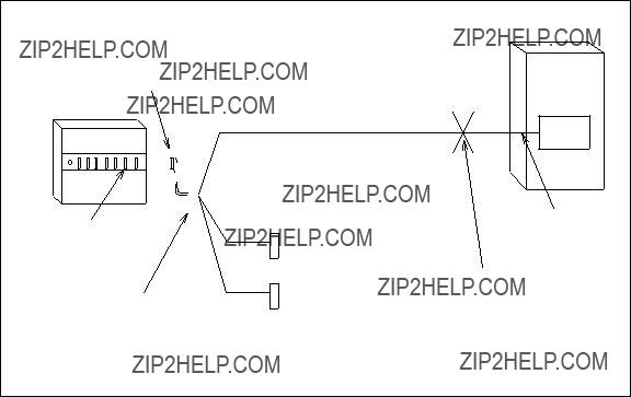
Figure
The AUDIX DCP channels are connected directly to the MERLIN II using
1.Assemble the system modules as shown in Figure
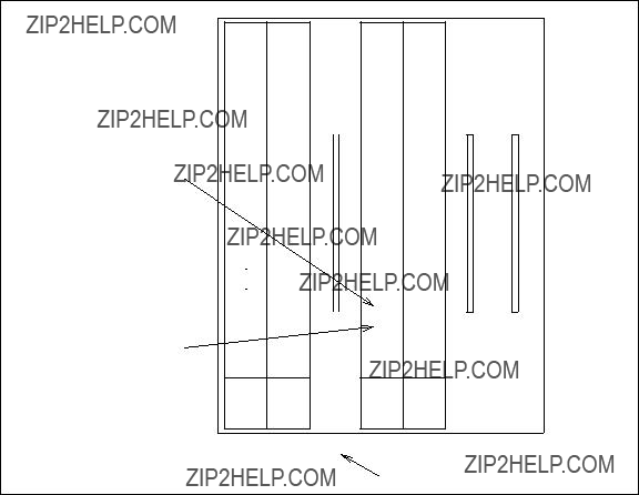
_______________________________________________________________________________________
_______________________________________________________________________________________
Figure
2.At the rear of the AUDIX cabinet is a
3.Plug one end of a
Repeat this step with the second
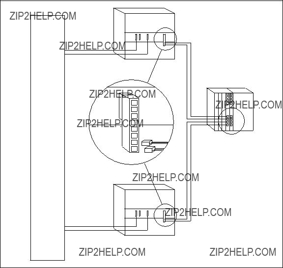
Figure
4.Run the other ends of the
Any digital module (008D) jack position will work. The jack position determines the number assigned to the AUDIX DCP data port.
5.Repeat steps 1 through 4 for each

_______________________________________________________________________________________
_______________________________________________________________________________________
SWITCH ADMINISTRATION
The BCSDC will design hunt groups for AUDIX networking so the customer does not need to do so. Always use the extension numbers and hunt sequences provided by the BCSDC for AUDIX networking administration.
The AUDIX networking port administration covered in this section is used in all AUDIX networking setups. The following switch administration is required:
???At the System 75, Generic 1, and Generic 3, you will be assigning two channels. These switches use only
???System 85 and Generic 2 use both
???The MERLIN II does not require administration for AUDIX DCP channels. The jacks used on the 008D module have ???xed dialing codes. At the AUDIX system, the MERLIN II connections appear only as Channels 2 and 4 (only
NOTE
If the
If you are using MPDM/M1* data modules to convert
System 75, Generic 1, and Generic 3 Administration
Use the following procedure to assign the AUDIX DCP channels (terminated at two DCP circuits).
1.Use ??????add
2.Set Type to pdm.
3.Set Port to the location of the TN754 circuit that is wired to the AUDIX DCP port (cable
4.Press ENTER .
5.Repeat steps 1 through 4 for each DCP port used.
6.Use ??????add
________________________________________________________________________________________________
________________________________________________________________________________________________
Use the hunt groups the BCSDC has designed for AUDIX networking.
NOTE
7.Set Group Extension to another unused extension. Use a DID extension if the AUDIX system is to be accessed from a remote AUDIX system.
8.Set Group Type to ucd.
9.Set Message Center to none.
10.Set ACD to n.
11.Press ENTER .
12.Go to Page 2 and assign the DCP extensions to this hunt group. If you are converting the AUDIX
NOTE
Assign extensions in the order determined by the BCSDC. For example, the hunt sequence may start with port 5.
System 85 Administration
System 85 can use both
1.Assign a class of service (cos) for the AUDIX networking ports that has
* Fields 2 through 10 may be assigned for toll fraud protection.
$ For remote networking con???gurations, if the AUDIX networking extension is dialing AAR or ARS to reach a remote AUDIX system, make sure an appropriate FRL is assigned to the AUDIX networking extensions??? cos (Proc 010, Word 3, Field 23).

_______________________________________________________________________________________
_______________________________________________________________________________________
2.The bearer capability of the AUDIX networking ports should be assigned to their class of service using Proc 010, Word 4.
* Value of this ???eld differs depending on networking con???guration.
3.Assign an extension number for each networking port, four extension numbers for the
The extension numbers shown are only examples; use the extensions from the BCSDC.
4.Assign the extensions to hunt to each other (use Proc 000, Word 2). You will administer hunting for four extensions if only the DCP ports are used, or six extensions if the
This sequence is only an example; use the hunt sequence from the BCSDC.
5.For each GPP equipment location, assign the following characteristics (use Proc 051, Word 1). Unless speci???ed, leave the ???eld dashed or blank.
a.Terminal Type ??? select one of the following:
???For DCP ports, administer terminal type as AP32 (Field 6 = 10)
???If converting
b.Originating Preference = Prime Appearance (Field 10 = 2)
c.Terminating Preference = None (Field 11 = 0)
d.Keyboard Dialing = active (Field 13 = 1)
_______________________________________________________________________________________
________________________________________________________________________________________________
________________________________________________________________________________________________
*This ???eld may be 10 for DCP ports or 4 for converted
6.For each GPP equipment location, assign two appearances with the following characteristics (Proc 052, Word 1):
a.Device Type = Basic Set (Field 6 = 0)
b.Member = 0 (???rst appearance), then 1 (second appearance) (Field 7 = 0 or 1)
c.Extension Number = extensions assigned above (Field 8)
d.Call Appearance Number on this Set = 1 (Field 9 = 1)
e.Line Type = Prime Line (Field 10 = 1)
f.Alert Type = alert (Field 11 = 1)
g.Home Terminal = home terminal (Field 12 = 1)
h.Originating Call Appearance Only = not originating only (Field 13 = 0)
i.SAC Group = not a SAC member (Field 14 = 0 on R2V4 or later systems)
7.Auxiliary tone pack: A System 85 must have at least one SN253C auxiliary tone pack in every module; this pack is administered using Proc 252, Word 2.
8.Tone detector pack (remote networking con???gurations): A System 85 requires an SN255 tone detector pack or an SN255B pack in applications requiring modems that use 2100 Hz answer tone (such as the AT&T 2296, 2248, or 2224). Four tone detectors should be assigned on each SN255 board; the
_______________________________________________________________________________________
_______________________________________________________________________________________
Generic 2 Administration
Generic 2 can use both
Some general notes on Generic 2 requirements include:
???Auxiliary tone pack: A Generic 2 with traditional modules must have at least one SN253C auxiliary tone pack in every traditional module; this pack is administered using Proc 252, Word 2. No administration is required for the TN748C tone pack in a Generic 2 universal module.
???Tone detector pack (remote networking con???gurations): A Generic 2 with traditional modules requires an SN255 tone detector pack, or an SN255B pack in applications requiring modems that use 2100 Hz answer tone (such as the AT&T 2296, 2248, or 2224). Four tone detectors should be assigned on each SN255 board; the
The TN748C board in a Generic 2 universal module can use channels 4 and 8 for tone detection; up to two
???Universal modules: If the switch is a Generic 2 with universal modules, make sure the AUDIX system has a TN366B, TN539, or TN539B ACC(E) board. Otherwise, you can only assign two of the four available DCP channels.
Manager III and Manager IV Administration
DEFINITY Manager III and Manager IV are covered in their own documentation sets. Refer to the appropriate manual for more information on administering systems using Manager III or Manager IV:
???DEFINITY?? Manager III Operations
???DEFINITY?? Manager IV Facilities Management Operations
???DEFINITY?? Manager IV Terminal Change Management Operations
???DEFINITY?? Manager IV System Administration
________________________________________________________________________________________________
________________________________________________________________________________________________
Manager II Administration
Manager II assignments for Generic 2 are as follows:
1.Assign all four extension numbers (or six if you are converting
Use a
ENHANCED MODE - PROCEDURE: 000, WORD: 1
SINGLE TERMINAL TRANSLATION
1.Extension or VDN: 32330
TERMINAL EQUIPMENT LOCATION
2.Module:
3.Cabinet: -
4.Carrier: -
5.Slot:
6.Circuit:
7.Class of Service: 10
8.Port Type: - Extension administered in Procedure 052 Word 1
9.Disable Signaling: -
DISPLAY ONLY
10.Recent Disconnect: 0 Extension is not in recent disconnect
11.Use the Procedure(s) Shown: 052
Figure
_______________________________________________________________________________________
_______________________________________________________________________________________
2.Assign all four extensions (or six if you are converting
NOTE
The default BCCOS 0 through 8 should not be modi???ed to support AUDIX networking. If a custom BCCOS is required, create a new BCCOS using the default values shown in PROC 014, Words 1 and 2. Refer to the DEFINITY Generic 2 Administration Procedures manual
The BCCOS 6 default parameters are also shown in Figure
5.Bearer Capability Class of Service: 6
6.Universal Code Calling ID:
Figure

________________________________________________________________________________________________
________________________________________________________________________________________________
ENHANCED MODE - PROCEDURE: 014, WORD: 1
CALL TYPES AND ACTION TAKEN
4.Voice: 0 Circuit switch the call
5.Voice Grade Data: 1 Insert a mode
6.Mode 0: 0 Circuit switch the call
7.Mode 1: 0 Circuit switch the call
8.Mode 2: 0 Circuit switch the call
9.Mode 3: 0 Circuit switch the call
10.Unknown Digital: 0 Circuit switch the call
11.Unknown Analog: 1 Insert a mode
12.Mode 3/2: 0 Circuit switch the call
13.X.25: 0 Circuit switch the call
Figure
3.The DCP extensions default to BCCOS 1. Change this to BCCOS 6 as shown in these examples. This allows the DCP port to communicate with either a digital or analog outside facility.
A call to/from this port will be circuit switched unless it is
_______________________________________________________________________________________
_______________________________________________________________________________________
ENHANCED MODE - PROCEDURE: 014, WORD: 2
BEARER CAPABILITY CLASS OF SERVICE - DATA OPTIONS
1. Bearer Capability COS: 6
DATA RATE
2.64000 bps: 1 Supported
3.56000 bps: 1 Supported
4.19200 bps: 1 Supported
5.9600 bps: 1 Supported
6.4800 bps: 1 Supported
7.2400 bps: 1 Supported
8.1200 bps: 1 Supported
9.300 bps: 1 Supported
10.Low Speed: 0 Not supported
11.Synchronous: 1 Synchronous
12.Duplex: 0 Full duplex
13.Clock: 0 Internal
14.Default Data Rate: 9 64000 bps
Figure

________________________________________________________________________________________________
________________________________________________________________________________________________
4.Assign the DCP equipment location as Dual Port Data (Proc 051, Word 1). Make the entries as shown in Figure
5.Repeat step 4 for the second DCP equipment location.
7.Option: 0 data only
PHYSICAL TYPE
8.Data: 1
9.Display: _
Figure

_______________________________________________________________________________________
_______________________________________________________________________________________
6.Assign line appearances to the DCP equipment location. Make the entries as shown in Figure
Manager II Administration for DCP Ports (Proc 052, Word 1). The extension shown in Field 8 is only an example.
7.The ???rst extension is assigned to Device Type 0 (Field 6) Member 0 (Field 7). Repeat step 6, only use Device Type 0 Member 1 and assign a different extension to it.
8.Repeat steps 6 and 7 for the second DCP equipment location. Assign two other extension numbers to Device Type 0 (Field 6) Members 0 and 1 (Field 7) for this equipment location.
If desired, you may display the extensions using Proc 052, Word 2.
ENHANCED MODE - PROCEDURE: 052, WORD: 1
10.Line Type: 1 Prime line
11.Ringing Type: 1 Ringing
12.Home Terminal: 1 Yes
13.Originating Only: 0 No
14.SAC Group: 0 No
Figure
9.After the extensions are assigned here, their BCCOS may be reset to 1. Go back to Procedure 000, Word 3 and check if the BCCOS is still 6. If not, reset it to 6 if necessary. Check each of the AUDIX networking extensions.
________________________________________________________________________________________________
________________________________________________________________________________________________
10. DCP Mode 1 Installation and Administration
_______________________________________________________________________________________
_______________________________________________________________________________________
In most cases where the customer wishes to use this type of network, it will be because the network connections are already in place. T1 facilities connect the Private Branch Exchange (PBX) to a network
SWITCH COMPONENT INSTALLATION
See the appropriate switch and/or feature documentation for installing circuit packs and wiring trunks on the switch.
SWITCH ADMINISTRATION
Check to make certain the customer???s switch and the central of???ce switch are compatible. For DCP Mode 1 networking, the trunk group used to transport the AUDIX calls must be DS1 and the DS1 pipe must employ
4ESS Administration
If not already done, the 4ESS must be translated for 56 Kbps operation as follows:
???The 4ESS facilities must be translated for
???If the 4ESS is using AMI, the System 75, System 85, or DEFINITY Communications System must be translated for ZCS (not B8ZS).
???The trunk types on the 4ESS and switch must match (for example, both may be translated as wink/wink type trunks).

________________________________________________________________________________________________
________________________________________________________________________________________________
System 75, Generic 1, and Generic 3 Administration
Administration depends on whether the customer is using static
NOTE
Any Generic 1 switches in a 56 Kbps network that includes a Generic 2 must be running at least Issue 7.2 software.
???Static Access: For static
???Using the add
???Using the change
???Using the change ds1 circuit pack form, set the signaling mode ???eld to
???Dynamic Access: For dynamic (voice and
???Using the add
???Using the change
???Using the change ds1 circuit pack form, set the signaling mode ???eld to

_______________________________________________________________________________________
_______________________________________________________________________________________
System 85 Administration
The following translations need to be completed for a System 85 for static switched 56 Kbps (dynamic access is not supported for System 85 R2V3 or R2V4; System 85 R2V2 does not support 56 Kbps networking). System 85 is administered as follows using the MAAP.
1.Using Procedure 010, Word 4, assign mode 1 data to the class of service associated with the AUDIX networking ports (Field 3 = 1).
2.Using Procedure 100, Word 1, translate the trunk group (tgroup) as follows:
a.Assign a dial access code (DAC) in Fields 2 through 5. The dial string used by the AUDIX networking ports must be routed via a dedicated (static) trunk group using this DAC.
b.Assign a DMI trunk type (Field 6 = 109). The DS1 facility used to transport the 56 Kbps call must employ
3.Using Procedure 101, set the following values:
a.Set Touch Tone In and Touch Tone Out to 1 (Fields 6 and 7 = 1).
b.Set the AVD bit for the trunk group to 0 (Field 17 = 0).

________________________________________________________________________________________________
________________________________________________________________________________________________
Generic 2 Administration
The following Manager II translations need to be completed for a Generic 2 for static switched 56 Kbps networking. For Generic 2 translations using dynamic 56 Kbps networking, contact the BCSDC.
NOTE
DEFINITY Manager III and Manager IV are covered in their own documentation sets. Refer to the list of documents in Chapter 9 to ???nd the appropriate manual for administering systems using Manager III or Manager IV.
1.Using Procedure 100, Word 1, make the assignments shown in Fields 1 through 9. The trunk group (76) and the dial access code/trunk ID code shown are only examples; enter the appropriate values supplied by the BCSDC.
To administer members of the trunk group, use Procedure 116.
NOTE
If you need to change the signaling type, use Procedure 100, Word 3.
ENHANCED MODE - PROCEDURE: 100, WORD: 1
TRUNK GROUP TRANSLATION
1. Trunk Group: 76
DIAL ACCESS CODE/TRUNK ID CODE
2.Digit 1: 7
3.Digit 2: 5
4.Digit 3: 1
5.Digit 4: -
6.Trunk Type: 41
7.Dial Access Restriction: 0 Access is allowed using DAC
8.Personal CO Line Appearance: 0 Not used for CO line appearance
9.Public Network Access/Egress: 1 Enabled
Figure
_______________________________________________________________________________________
_______________________________________________________________________________________
2.Using Procedure 100, Word 2, assign BCCOS 7 to the trunk group (trunk group 76 is only an example).
NOTE
BCCOS 7 is the default and should not be modi???ed. However, if BCCOS 7 has been modi???ed at your site, use a custom BCCOS that has the default values of BCCOS 7 (one that uses
ENHANCED MODE - PROCEDURE: 100, WORD: 2
TRUNK GROUPS - MODEM POOLING AND BCCOS
MODEM POOLING
3.Originate Mode: _
4.Answer Mode: _
5.Modem Type: _
6.First Choice: _
7.Test Type: _
Figure

________________________________________________________________________________________________
________________________________________________________________________________________________
3.Using Procedure 101, Word 1, make the assignments shown below:
ENHANCED MODE - PROCEDURE: 101, WORD: 1
TRUNK GROUP CHARACTERISTICS
1.Trunk Group: 76
2.Balance: 0 Disabled
TIMED RECALL
10.Time: 0
11.Level: 0 Recall occurs when recall time expires
12.CDR Variable Timer:
13.Pad Group: 0 Determined by trunk type in Procedure 100 Word 1
14.Tie Toll: 0 Not toll restircted
15.APLT Features Allowed: 0 Disabled (CCSA trunk)
16.Disconnect Supervision: 0 Disabled
Figure

_______________________________________________________________________________________
_______________________________________________________________________________________
LOOPBACK TESTING
AT&T Network Systems requires loopback capabilities in order to test and support AUDIX networking over switched digital services (SDS). With R1V7 software and a TN539B ACCE, this test can be enabled via the maintenance : network form. On R1V5 and R1V6 systems, an MPDM/M1* is required for loopback testing.
Loopback Testing for R1V7
On AUDIX R1V7 systems, you can test the connection between the local AUDIX system and the 56 Kbps serving of???ce (SO), as shown in Figure
While a channel is in loopback mode, it will be unavailable to send information to remote systems or receive information from remote systems. Incoming calls will be answered, but the calling system will be unable to establish a connection; eventually it will drop the call and attempt to call back at its next scheduled transmission time.
Also, if you put a channel in loopback mode, any active calls will be dropped. It is therefore recommended that before you perform this test you check the status of the channel. It is also not a good idea to perform this test during peak traf???c times.
1. Go to the maintenance : network form. Set select test to 7 to test a 56 Kbps network
NOTE
If you have an MPDM/M1* between the AUDIX system and the PBX, you may also test channels 5 or 6 (the
2.Have the serving of???ce place a call to the telephone number assigned to the channel you speci???ed on the maintenance : network form. If the test is successful, any data the serving of???ce sends over the AUDIX channel will be echoed back.
3.Go to the maintenance : network form. Set select test to 9 to take the channel out of

________________________________________________________________________________________________
________________________________________________________________________________________________
SYSTEM 85
DCP
POINT-
OF-
PRESENCE
SWITCH
. . . . . . . . . . . . . . . . . . . . . . . . .
MAINTENANCE: NETWORK FORM:
NETWORK LOOPAROUND START 56/64 Kbps
Figure
Loopback Testing for R1V5 and R1V6
For R1V5 and R1V6, loopback capabilities are provided by an MPDM/M1*.
Setting Up the MPDM/M1*
NOTE
The MPDM/M1* used for loopback testing is not the same one used for the
To install the MPDM/M1*, complete the following steps:
1.If the customer did not order an MPDM/M1*, modify the MPDM to support 56 Kbps by completing the following steps.

_______________________________________________________________________________________
_______________________________________________________________________________________
NOTE
If the faceplate of the MPDM reads ACCUNET, then the
a.Install the 56 Kbps
b.Install the V.35 DTR card in the MPDM. The V.35 card allows a call to be answered without an attached DTE device.
To see if the V.35 card has already been installed, power up the MTDM without having a DTE attached. The Terminal Ready LED on the MPDM will be on if the V.35 DTR interface has previously been installed.
c.Solder two loops or build and connect a male loopback plug to make the connections shown in Figure
V.35 MALE CONNECTOR
P (Tx1)
R (Rx1)
S (Tx2)
T (Rx2)
Figure
2.Install the MPDM/M1* by following the instructions that come with the data module.
3.Set all MPDM option switches to OFF (left) except the following:
???Set OFF/56K to 56K
???Set ASYNCH/SYNC to SYNC
???Set EXT/INT to INT
???Set OFF/ANET to ANET
???Set OFF/AANS to AANS

________________________________________________________________________________________________
________________________________________________________________________________________________
Performing Loopback Test
AT&T Network Systems requires loopback capabilities in order to test and support AUDIX networking over switched digital services (SDS).
NOTE
The AUDIX networking ports will be unavailable for the duration of the loopback test. Therefore, the test should not be conducted during
In order to conduct a loopback test, you must have installed the loopback MPDM/M1*. One MPDM/M1* is required per customer location, not per AUDIX system. (The MPDM/M1* must have the V.35 interface described earlier in this chapter.) You will also need to disconnect the AUDIX Networking Breakout Cable
When a loopback test is to be conducted, complete the following steps:
1.Busy out the AUDIX networking ports as follows:
a.If the
b.Use the maintenance : network form to busy out all of the AUDIX networking ports.
2.Connect the loopback MPDM/M1* (with the V.35 interface card) as follows:
???If you are using the
???If a 356A adapter is available (see Figure
???If a 356A adapter is not available, patch a 103A adapter to the DCP interface for the ???rst physical port (ELL) at the
???If you are using the
3.Put the loopback MPDM/M1* (with the V.35 interface) into normal mode.
4.Have Network Systems conduct the loopback test on the port connected to the loopback MPDM/M1*. Once the MPDM/M1* answers the call, put it into remote loopback mode.
5.When the test is completed, have Network Systems disconnect the call or press the ORIGINATE/DISCONNECT switch on the loopback MPDM.
6.Connect the network breakout cable

_______________________________________________________________________________________
_______________________________________________________________________________________
7.If the
8.Use the maintenance : network form to unbusy the AUDIX ports.
Figure
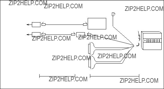
Figure

11. DCP Mode 2 Installation and Administration
_______________________________________________________________________________________
_______________________________________________________________________________________
This chapter explains how to install and translate
INSTALLING A 2296A AND MTDM IN A MODEM POOL
The following shows how to install and administer 2296A modems and MTDM data modules in their
Do not apply power to the cabinet or any related equipment until all components are installed and ready for service.
WARNING
Install the Modem Pool Cabinet
The modem pool cabinet requires a 57 to 63 Hz, 105 to 129 VAC circuit. Expect to draw a maximum of 1200 watts. (This circuit should come from the same AC Distribution panel that powers the AUDIX, and power should not be controlled by the switch. The circuit should not share power with room lighting or other electrical devices that could cause electrical interference.)
A power strip should be installed at the back of the cabinet along the bottom
Install the Multiple Mountings
Each mounting plugs into the cabinet power strip and will draw 52 watts of power. The mountings operate in an ambient temperature range of 40 to 120 degrees F (4.44 to 48.8 degrees C) and a relative humidity range of 5 to 95 percent, noncondensing. The altitude limit is 10,000 feet above sea level.
Figure
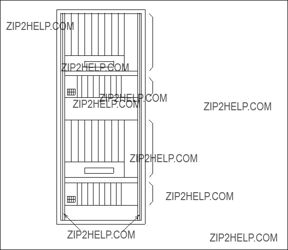
________________________________________________________________________________________________
________________________________________________________________________________________________
SIDE RAILS
105A MOUNTING
WITH 8 MODEMS
77A MOUNTING
WITH 8 DATA SETS
105A MOUNTING
WITH 8 MODEMS
77A MOUNTING
WITH 8 DATA SETS
NOTE: Use 46A2 mounting if MTDMs are used instead of 7400As.
Figure
Install the Modems and Data Sets
Each modem and data set plugs into the mounting and will draw 30 watts of power. The modems and data sets also operate in an ambient temperature range of 40 to 120 degrees F (4.44 to 48.8 degrees C) and a relative humidity range of 5 to 95 percent, noncondensing. The altitude limit is 10,000 feet above sea level.
_______________________________________________________________________________________
_______________________________________________________________________________________
Figure
Figure

________________________________________________________________________________________________
________________________________________________________________________________________________
Use the following steps to install the modems and data sets.
1.Before installing a 2296A modem, check the feature package module located in the
CAUTION
Do not pull the feature package or other module from the 2296A when power is applied. Turn the power switch at the back of the 2296A OFF and unplug the 2296A power cord from the mounting.
The Automatic Calling Unit (ACU) and AUTOCALL modules are not required and should be removed if present. The Microcom Networking Protocol (MNP) module is only required if the data rate is 19.2 Kbps. In most AUDIX
2.Install the 2296A modems in 105A slots. Start at the left. The modems must contact their backplane connector. Set the following options located at the top of the 2296A faceplate under the sliding panel:
The LCD display will be used to set internal options once power is applied.
3.Before installing the MTDMs, verify that they contain the new processor and TRIC 4 chips (see Figure
4.Set the following options on the MTDM circuit card:
5.Install the MTDM data sets in 46A2 slots. Start at the left. Each MTDM is paired with a modem. The MTDMs must make contact with the backplane connector.
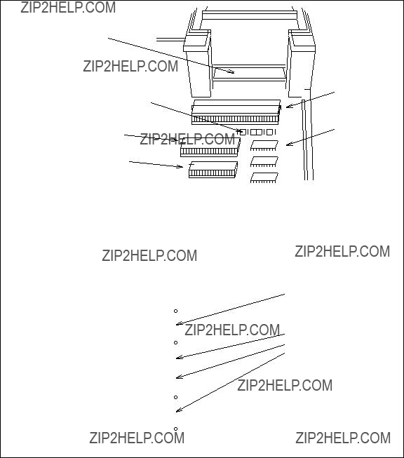
_______________________________________________________________________________________
_______________________________________________________________________________________
VERIFY THAT THE DAUGHTER
BOARD USES TRIC 4 CHIPS (CODED 229EJ)
JUMPER NO. 9 PLACED IN NEW
POSITION AS SHOWN (SEE 

 IC3
IC3
EXPLODED VIEW BELOW)
IC4 FROM
D181470
Figure
6.Set the following options on the face of the MTDM. The arrows (< for left, > for right) indicate which direction the rockers should be set. The speed shown is 9600 bps.
_________________________________________

________________________________________________________________________________________________
________________________________________________________________________________________________
???
???
???
???
???
???
???
???
???
???
???
???
???
???
???
???
???
???
???
???
Install the
Figure
1.Connect the D Lead Control cable
2.Connect one end of a
3.Connect the other end of this cable to the switch
Record the telephone number of each modem on the space above the display panel.
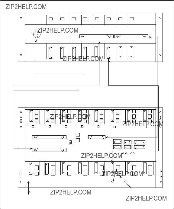
_______________________________________________________________________________________
_______________________________________________________________________________________
ONE OF 8
NOTE: This ???gure shows the MTDM rack on top.
Figure

________________________________________________________________________________________________
________________________________________________________________________________________________
4.The switch to the right of the RJ21X PERMISSIVE connector must be in the down position.
5.Set the eight Make Busy/Enable switches to the enable position (DOWN).
6.Connect one end of a
7.Connect the other end of this cable to the switch
8.Connect a ground strap from the signal ground (SG) to the frame ground (FG) on the 105A.
9.Make sure the cabinet is not connected to power, then connect the mounting power cords to the cabinet power strip.

_______________________________________________________________________________________
_______________________________________________________________________________________
Install the MTDM and 2296A Cables
1.Connect a Data Terminal Equipment (DTE)
2.At the back of the modem, make sure the power switch is OFF (0 position).
3.At the back of the mounting, connect one of the eight power cords to the AC power jack on the back of the modem.
2296A Option Settings
1.First make sure that the power switch for each MTDM and each 2296A is OFF.
2.Plug the cabinet power cord into the circuit provided. The LCD display on the front of the 105A should light up.
3.Turn the power switch at the back of the modem ON (1).
4.Press the select button on the front of the mounting below the modem to be optioned. The button should light up and the display will show the information for this modem.
5. Press MENU SEL until OPt is displayed.
6. Press . (dot) once.
15.Set option 99 to 2 to relock this modem???s options.

Figure
_______________________________________________________________________________________
_______________________________________________________________________________________
INSTALLING A 7400A IN A MODEM POOL
The 7400A Data Service Unit (DSU) can replace the MTDM in modem pooling applications on a System 75, System 85, DEFINITY Generic 1, Generic 2, or Generic 3. Instructions for installing a 7400A DSU in the
1.Disconnect the power cord, the line cord, and the
2.Open the top door of the 7400A by inserting the tip of a
3.Rotate the 7400A so that you are viewing it from the front. Look straight down at the inside and locate the large silver arrow pointing toward the back of the set. The arrow points to the EIA connector board. The board is perpendicular to the plane of the arrow. You can see it at the point of the arrow.
4.Look at the EIA board from the front of the set. You should see DTE printed on the left hand corner of the board. If you see DCE, pull the board up until it is completely free. Rotate it until you can read DTE from the front of the 7400A and plug the board in again.
5.Close the door by hooking the hinges under the front housing and then snapping the rear tabs into place.
6.Check the position of the slide switch located near the front of the access door opening. It should be positioned to the left as viewed from the front of the unit (position B). This is the normal position for operation in a modem pool. There are some 9600 bps modems which will not operate properly with the switch in this position, particularly those modems employing data compression and error correction (such as the Hayes SMARTMODEM 9600). For these modems, position the switch to the right (position A).
7.Plug one end of the
8.Plug the power supply cord into the receptacle labeled POWER on the 7400A.
9.Plug one end of the
10.Make sure that your PBX is administered to support the 7400A in a modem pool arrangement. See the 7400A Modem Pool Installation Guide
11.Plug the power supply into an AC power outlet.
12.Use the front panel to set the 7400A options according to the following table. See the 7400A Data Module User???s Manual

________________________________________________________________________________________________
________________________________________________________________________________________________
* To enable stepdown (slower data transmission speed), set 4800 speed to ON. On the modem, set Options 50, 56, and 73 to y.
Continue the installation according to the following steps. The 7400A is con???gured for DTE modem pool operation with
13.Connect the
AUDIX Networking (Modem Pooling) With 7400A DSUs]. Then plug each numbered connector
14.Connect the
15.Connect the
16.Put the cover on the bridging adapter.
17.Connect the other end of the
Figure
18.From the back of the rack, connect the appropriate M25B cable to its
19.Drape each interface cable through its plastic twist lock and twist the top ends of the lock to secure each cable. Make sure each modem is interconnected through the
20.To test the remote connection and the administration of the system, run the

________________________________________________________________________________________________
________________________________________________________________________________________________
INSTALLING
System 75/85, System 75 XE, Generic 1, Generic 2, and Generic 3
If the AUDIX is equipped with the TN366B, TN539, or TN539B
???AT&T Paradyne 3820 modem
???AT&T Paradyne DM424 modem
???AT&T 2296A modem
NOTE
Equivalent modems such as the AT&T Paradyne DL424 instead of the DM424 modem could be used.
Figure
104A
MODEM
 M25B
M25B
Figure
_______________________________________________________________________________________
_______________________________________________________________________________________
2296A Modem AUTOCALL Dialer Module, Type 2A4
The 2296A requires a dialer module when in a
1.Disassembling the Modem:
a.Make sure power is turned OFF.
b.Disconnect all cords from the modem.
c.Turn the modem upside down and remove the six recessed screws along the edges of the modem.
d.Hold the top and bottom halves of the housing together as you turn the modem
e.Gently remove the top half of the housing.
f.Disconnect the ribbon cable that connects the front panel to the right side of the circuit pack (when facing the front of the modem).
g.Remove the front panel by lifting it straight up.
h.Lift the front of the circuit pack about 1 inch, pull the circuit pack forward about 1 inch, and set it down.
2.Inserting the Dialer:
a.At the side of the modem???s circuit pack labeled EXPANSION SLOT A, tilt the circuit pack up from the housing until the slot is visible (1 or 2 inches up).
b.Orient the dialer module with the metal tab toward the rear of the modem circuit pack. Insert the dialer module in EXPANSION SLOT A.
When fully inserted, the hole in the metal tab should be positioned over a threaded hole in the modem???s circuit pack.
c.Move the modem???s circuit pack back to its original position with the connectors at the rear extending through the back of the housing. Make sure the notches cut into the sides of the circuit pack align with the supports in the housing.
d.Fasten the dialer module in place with the screw shipped with the module.
e.Keep a record of which dialer module is installed (AUTOCALL DIALER).
3.Assembling the Modem:
a.Place the front panel back in the housing. Insert the bottom (hinged side) of the panel ???rst, then rotate the front panel back into place.
b.Reconnect the ribbon cable to the connector on the right side of the modem???s circuit pack. Make sure the cable does not get in the way when replacing the top half of the housing and installing the screws.
c.Replace the top half of the housing. Check the front and rear panels to be sure that the housing is positioned correctly.
d.Hold the top and bottom halves of the housing while turning the modem over.
e.Install the six screws and tighten.

________________________________________________________________________________________________
________________________________________________________________________________________________
2296A Modem Option Settings
All 2296A modems now are shipped with a memory module. In earlier versions, a 140C1 Memory Module V1.1 or V1.2 had to be installed in the
Two groups of switches are located at the top of the 2296A modem faceplate. Set the switches according to the following table:
For instructions on how to set the 2296A option settings from the front panel, see 2296A Option Settings
???Set Option 99 to 1 (allows options to be changed).
???Set all options to their default.
???Set Option 50 (async/sync) to y.
???Set Option 56 (Early DSR) to y.
???Set the speed to 9600 (same as the MTDM).
???Set Option 99 back to 2 (two).
To set the options from a terminal, use the follow initialization string:
at&f x1 v0 m0 e0 &c1 &d2 &s1 s0=2 &w RETURN
If successful, the response will be 0. A response of anything other than 0 indicates a fail.

_______________________________________________________________________________________
_______________________________________________________________________________________
DM424 Modem Option Settings
Only switch 6 should be in the ON (DOWN) position. There is also a DIP switch at the back of the modem. All DIP switches should be in the OFF (UP) position. If you change any setting, make sure power is cycled. This will activate the new setting(s).
The modem initialization string must be entered manually from the keyboard of a 9600 bps terminal interface. If possible, use a terminal that does not require Data Set Ready (DSR) to be active; however, most terminals (including the 513 BCT and TELETYPE 5420) require that DSR be active at the modem in order for them to send characters to it. The DM424 modem has DSR active from the factory, but once the following initialization string is sent, DSR becomes inactive. [The ??????&b2?????? required for
If you are using a terminal that requires DSR to be active and you need to resend the initialization string for any reason, or if you want to receive a response as to whether the initialization was successful, you need to ???rst insert an
The initialization string required for the DM424 follows. Spaces have been inserted to improve readability; they are ignored by the command interpreter.
at&f *s0 *e0 &b2 x1 v0 m0 e0 &w RETURN
The terminal screen will show whether the initialization was successful (if you are using a terminal that requires DSR to be active, you need to have inserted an
Paradyne 3820 Modem Option Settings
The modem initialization string must be entered manually from the keyboard of a 9600 bps terminal interface. If possible, use a terminal that does not require Data Set Ready (DSR) to be active; however, most terminals (including the 513 BCT and TELETYPE 5420) require that DSR be active at the modem in order for them to send characters to it. The Paradyne 3820 modem has DSR active from the factory, but once the following initialization string is sent, DSR becomes inactive. [The ??????&s1?????? required for stand- alone modem pool operation deactivates DSR, even though the Modem Ready (MR) lamp would indicate otherwise.]
If you are using a terminal that requires DSR to be active and you need to resend the initialization string for any reason, or if you want to receive a response as to whether the initialization was successful, you need to ???rst insert an
The initialization string required for the Paradyne 3820 follows. Spaces have been inserted to improve readability; they are ignored by the command interpreter.
at&f0 &d2 &s1 \d3 \n0 e0 v0 x1 s41=3 s43=1 s76=1 s78=1 &w0 RETURN
The terminal screen will show whether the initialization was successful (if you are using a terminal that requires DSR to be active, you need to have inserted an

________________________________________________________________________________________________
________________________________________________________________________________________________
If you are using a terminal that requires DSR to be active (for example, a 513 BCT or TELETYPE 5420), you must install an
To install the
1.Insert the breakout box in the
2.Using the switches on the breakout box, open Pin 6 (DSR).
3.Jumper Pin 6 on the terminal side to +v on the breakout box. This will provide DSR active to the terminal.
6.
7.Remove the breakout box and reconnect the modem to the modem pool.
To install cabling, do the following:
1.Connect an M25B
2.Connect the modular cord that comes with the modem to the back of the modem and to one side of a 104A connecting block.
3.Connect the
4.Wire the connecting block to the ports on the switch. Wire the modem to the analog port and wire the 7400A to the digital port.

_______________________________________________________________________________________
_______________________________________________________________________________________
7400A DSU Option Settings
The 7400A has an internal DCE/DTE card. The DTE side should be facing the front of the set. Set the following options when the 7400A is installed in a

________________________________________________________________________________________________
________________________________________________________________________________________________
ADMINISTERING THE SWITCH FOR MODEM POOLING
This section describes switch administration for a System 75, System 85, or DEFINITY Generic 1, Generic 2, or Generic 3.
If you are adding modem pool members, ???ll in the following before starting. For System 75, System 75 XE, Generic 1, Generic 2 (universal module), and Generic 3, locate the TN circuit packs shown below. For System 85 and Generic 2 (traditional module), locate the SN packs:
???TN754 or SN270B connected to
???TN754 or SN270B connected to
???TN754 or SN270B connected to
???TN754 or SN270B connected to
???TN742/TN746B or SN243B connected to
???TN742/TN746B or SN243B connected to
???TN742/TN746B or SN243B connected to
???TN742/TN746B or SN243B connected to
NOTE
On System 75, Generic 1, or Generic 3, lines (or stations) and trunks can reside on the same board for analog circuits. For digital circuits, lines and trunks should not reside on the same pack or the
On System 85 or Generic 2, only
System 75, Generic 1, and Generic 3 Administration
Use the following steps to administer the switch for modem pooling:
1.Using change
2.Using add
ENTER . The screen will be ???lled in as shown in Figure
Make the entries as shown. Analog and digital assignments correspond to the equipment locations of the TN742 or TN746B and the TN754 circuits, respectively. When all entries are made, press
ENTER .

_______________________________________________________________________________________
_______________________________________________________________________________________
add
Figure
System 85 Administration
Use the following steps to administer a System 85 for modem pooling using a MAAP:
1.Assign a bearer capability of mode 0 data to the class of service for the AUDIX networking extensions (Proc 010, Word 4, Field 3 = 4).
2.Procedure 100, Word 1 (for the digital side):
a.Enter the trunk group number (tgroup1) in Field 1. A dial access code is not required (Fields 2 through 5).
b.Set Trunk Type to 102 (Field 6 = 102).
c.Set Dial Access Restriction to 0 (Field 7 = 0).
d.Set CO Line Appearance to 0 (Field 8 = 0).

________________________________________________________________________________________________
________________________________________________________________________________________________
3.Procedure 100, Word 2 (for the digital side):
a.Enter the trunk group number (tgroup1) in Field 1.
b.Set the data rate for each speed optioned for the data modules in the modem pool in Fields 2 through 10.
NOTE
A data rate of 64 Kbps should always be translated for the modem pool in addition to the data rates optioned on the data module; this will ensure that a modem pool is selected when an incoming data call is directed to an AUDIX DCP port. If 64 Kbps is not translated, the
c.Set Synchronous to 0 for asynchronous operation (Field 11 = 0).
d.Set Duplex to 0 for full duplex (Field 12 = 0).
e.Set Modem Pool Mode - Originate to 1 (Field 13 = 1).
f.Set Modem Pool Mode - Answer to 1 (Field 14 = 1).
g.Set Modem Pool - Modem Type to 1 (Field 15 = 1).
h.Set Modem Pool - Clock to 0 (Field 16 = 0).
i.Set Modem Pool - First Choice to 1 (Field 17 = 1).
j.Set Test Type to 0 (to turn off periodic
k.Set Host Access Clock to 0 (Field 19 = 0).
* = data rate (translate 64 Kbps in addition to optioned rates, usually 9600 bps) $ = test type (see item j above)
4.Procedure 100, Word 1 (for the analog side):
a.Enter the trunk group number (tgroup2) in Field 1. A dial access code is not required (Fields 2 through 5).
b.Set Trunk Type to 101 (Field 6 = 101).
c.Set Dial Access Restriction to 0 (Field 7 = 0).
d.Set CO Line Appearance to 0 (Field 8 = 0).
_______________________________________________________________________________________
_______________________________________________________________________________________
5.Procedure 180, Word 1:
a.Enter the digital trunk group number (tgroup1) in Field 1.
b.Set Digital Equipment Location to one of the digital trunk circuits (Fields 3 through 7).
c.Set Analog Trunk Group to the analog trunk group number (Field 8).
d.Set Analog Equipment Location to the analog trunk circuit (Fields 9 through 13) paired with the digital trunk circuit of Fields 3 through 7.
Modem Pooling Testing
After assigning modem pooling on System 85 or Generic 2, test the
1.Use Procedure 100, Word 2 to enable demand testing:
On System 85: Set Field 18 to 1 (if it is displaying a 0).
On Generic 2: Set Field 7 to 1 (if it is displaying a 0).
2.Use Procedure 646 to test the modem pool:
a. Press NEXT TEST once (Field 1 = 2).
b.In Field 2, enter a ???0???.
c.In Field 3, enter the digital or analog trunk group number.
3.Use Procedure 100, Word 2 to disable demand testing (if you changed Field 7 or 18 to 1 prior to testing):
On System 85: Set Field 18 back to 0 (if it was previously displaying a 0).
On Generic 2: Set Field 7 back to 0 (if it was previously displaying a 0).
4.Use Procedure 620 to test the analog facilities: Run Test 2 on the analog circuits (SN243B).
5.Use Procedure 622 to test the digital facilities:
Run Test 2 on the digital circuits (SN270B or TN754).

________________________________________________________________________________________________
________________________________________________________________________________________________
Generic 2 Administration
The following Manager II translations need to be completed on Generic 2 to implement modem pooling.
NOTE
DEFINITY Manager III and Manager IV are covered in their own documentation sets. Refer to the list of documents in Chapter 9 to ???nd the appropriate manual for administering systems using Manager III or Manager IV.
1.Using Procedure 100, Word 1, make the assignments shown in Fields 1 through 9 for the digital side of the modem pool. Refer to Figure
The trunk group (130) and the dial access code/trunk ID code shown are only examples; enter the appropriate values supplied by the BCSDC.
ENHANCED MODE - PROCEDURE: 100, WORD: 1
TRUNK GROUP TRANSLATION
1. Trunk Group: 130
DIAL ACCESS CODE/TRUNK ID CODE
2.Digit 1: 2
3.Digit 2: 1
4.Digit 3: 5
5.Digit 4: -
6.Trunk Type: 102 Digital data modem pool (18)
7.Dial Access Restriction: 0 Access is allowed using DAC
8.Personal CO Line Appearance: 0 Not used for CO line appearance
9.Public Network Access/Egress: 0 Disabled
Figure
_______________________________________________________________________________________
_______________________________________________________________________________________
2.Using Procedure 100, Word 2, make the assignments shown in Fields 1 through 7. Assign a custom BCCOS to the trunk group (trunk group 130 and a custom BCCOS of 10 are shown only as examples). The custom BCCOS should mirror the default BCCOS 1 as shown in Figure
Manager II Administration for Digital Side of Modem Pooling (Proc 100, Word 2).
NOTE
Refer to the DEFINITY Generic 2 Administration Procedures manual
for the default values of BCCOS 1 if needed.
ENHANCED MODE - PROCEDURE: 100, WORD: 2
TRUNK GROUPS - MODEM POOLING AND BCCOS
MODEM POOLING
3.Originate Mode: 1
4.Answer Mode: 1
5.Modem Type: 1
6.First Choice: 1
7.Test Type: 0
Figure

________________________________________________________________________________________________
________________________________________________________________________________________________
3.Using Procedure 014, assign a custom BCCOS that is translated with all the speeds optioned for the data modules in the modem pool. The custom BCCOS should mirror the default BCCOS 1 except for the data rates chosen (BCCOS 1 automatically defaults to all speeds.)
In Figure
ENHANCED MODE - PROCEDURE: 014, WORD: 1
BEARER CAPABILITY CLASS OF SERVICE - CALL OPTIONS
CALL TYPES AND ACTION TAKEN
4.Voice: 0 Circuit switch the call
5.Voice Grade Data: 1 Insert a mode
6.Mode 0: 0 Circuit switch the call
7.Mode 1: 0 Circuit switch the call
8.Mode 2: 0 Circuit switch the call
9.Mode 3: 0 Circuit switch the call
10.Unknown Digital: 0 Circuit switch the call
11.Unknown Analog: 1 Insert a mode
12.Mode 3/2: 0 Circuit switch the call
13.X.25: 0 Circuit switch the call
Figure

_______________________________________________________________________________________
_______________________________________________________________________________________
4.Using Procedure 014, Word 2, select the data rates that will be used by the data modules in the modem pool. Figure
NOTE
A data rate of 64 Kbps should always be translated for the modem pool in addition to the data rates optioned on the data module; this will ensure that a modem pool is selected when an incoming data call is directed to an AUDIX DCP port. If 64 Kbps is not translated, the
ENHANCED MODE - PROCEDURE: 014, WORD: 2
BEARER CAPABILITY CLASS OF SERVICE - DATA OPTIONS
1. Bearer Capability COS: 10
DATA RATE
2.64000 bps: 1 Supported
3.56000 bps: 0 Not supported
4.19200 bps: 0 Not supported
5.9600 bps: 1 Supported
6.4800 bps: 0 Not supported
7.2400 bps: 0 Not supported
8.1200 bps: 0 Not supported
9.300 bps: 0 Not supported
10.Low Speed: 0 Not supported
11.Synchronous: 0 Asynchronous
12.Duplex: 0 Full duplex
13.Clock: 0 Internal
14.Default Data Rate: 9 64000 bps
Figure

________________________________________________________________________________________________
________________________________________________________________________________________________
5.Using Procedure 100, Word 1, make the assignments shown in Fields 1 through 9 for the analog side of the modem pool. Refer to Figure
The trunk group (131) and the dial access code/trunk ID code shown are only examples; enter the appropriate values supplied by the BCSDC.
ENHANCED MODE - PROCEDURE: 100, WORD: 1
TRUNK GROUP TRANSLATION
1. Trunk Group: 131
DIAL ACCESS CODE/TRUNK ID CODE
2.Digit 1: 2
3.Digit 2: 1
4.Digit 3: 5
5.Digit 4: -
6.Trunk Type: 101 Analog data modem pool (27)
7.Dial Access Restriction: 0 Access is allowed using DAC
8.Personal CO Line Appearance: 0 Not used for CO line appearance
9.Public Network Access/Egress: 0 Disabled
Figure
_______________________________________________________________________________________
_______________________________________________________________________________________
6.Using Procedure 100, Word 2, make the assignments shown in Fields 1 through 7. Assign BCCOS 5 to the trunk group (trunk group 131 is only an example). Refer to Figure
NOTE
BCCOS 5 is the default and should not be modi???ed. However, if BCCOS 5 has been modi???ed at your site, use a custom BCCOS that has the default values of BCCOS 5. Refer to the DEFINITY Generic 2 Administration Procedures manual
ENHANCED MODE - PROCEDURE: 100, WORD: 2
TRUNK GROUPS - MODEM POOLING AND BCCOS
MODEM POOLING
3.Originate Mode: -
4.Answer Mode: -
5.Modem Type: -
6.First Choice: -
7.Test Type: -
Figure

________________________________________________________________________________________________
________________________________________________________________________________________________
7.Use Procedure 180, Word 1 to pair up the digital trunk group with the analog trunk group.
Use appropriate entries for this procedure. The trunk groups shown (130 and 131) are only examples.
ENHANCED MODE - PROCEDURE: 180, WORD: 1
Figure
12. DCP Mode 3 Installation and Administration
_______________________________________________________________________________________
_______________________________________________________________________________________
Digital Communications Protocol (DCP) Mode 3 uses 64 Kbps,
???Local Networking: If you are installing a DCP Mode 3 network for two or more colocated (local) AUDIX systems (the AUDIX systems are connected to the same switch), refer to Chapter 9, DCP Cabling and Administration. There you install and translate each AUDIX system with the extension numbers required for each network channel. There are no requirements except extension numbers for a local AUDIX network.
???Remote Networking: If you are installing a DCP Mode 3 network that requires interlocation facilities, these facilities are typically T1 Carrier employing common (clear) channel signaling or an Integrated Systems Digital Network (ISDN) pipe.
This chapter covers administration and testing for DCP Mode 3 AUDIX networking setups.
SWITCH COMPONENT INSTALLATION
See the appropriate switch and/or feature documentation for installing circuit packs and wiring trunks on the switch.
SWITCH ADMINISTRATION
See the appropriate switch and/or feature documentation for ISDN administration. For DS1 administration of either local or remote AUDIX networking setups, see the following sections.
System 75, Generic 1, and Generic 3 Administration
The DS1 circuit pack uses the Common Channel Signaling mode to provide 23 trunks for data transmission and one channel for signaling. The DS1 trunk group must be assigned for AV/D.
At this time, use standard AV/D DS1 administration. Any speci???c assignments that become necessary for AUDIX networking will be covered in future issues of this document.

________________________________________________________________________________________________
________________________________________________________________________________________________
System 85 Administration
The DS1 circuit pack uses the Common Channel Signaling mode to provide 23 trunks for data transmission and one channel for signaling. The DS1 trunk group must be assigned for AV/D using the following MAAP procedures.
1.For local and remote AUDIX setups: Assign a bearer capability of mode 0 data to the class of service for the AUDIX networking extensions (Proc 010, Word 4, Field 3 = 4).
2.Assign a trunk group and trunk type using Procedure 100, Word 1. Assign members to the trunk group using Procedure 116.
3.For remote AUDIX setups only: The trunk group used to transport the AUDIX networking call must be DS1, and the DS1 pipe must employ 24th channel signaling.
a.Enter the trunk group number (tgroup) in Field 1.
b.Make sure Touch Tone In and Touch Tone Out are set to 1 (Fields 6 and 7 = 1).
c.AVD must be set to 1 (Field 17 = 1).
4.For remote networking con???gurations using AAR or ARS: If the local AUDIX DCP extensions dial AAR or ARS to reach a remote AUDIX system, make sure the FRL assigned to the AUDIX networking extensions??? cos is of a suf???cient value to get over the pattern and preference to allow calls from mode 0 data endpoints (Proc 309, Word 5, Field 10 = 1, or Proc 321, Word 5, Field 9 = 1).
Generic 2 Administration
This section describes the Manager II translations that must be completed on Generic 2 to implement DCP Mode 3 networking on AUDIX systems.
NOTE
DEFINITY Manager III and Manager IV are covered in their own documentation sets. Refer to the list of documents in Chapter 9 to ???nd the appropriate manual for administering systems using Manager III or Manager IV.
1.For local and remote AUDIX setups: You should have already assigned BCCOS 6 to the AUDIX DCP extensions in Chapter 9. Refer to Chapter 9 if necessary and check Figure
2.For remote AUDIX setups only: The trunk group used to transport the AUDIX networking call must be DS1, and the DS1 pipe must employ 24th channel signaling.
_______________________________________________________________________________________
_______________________________________________________________________________________
Using Procedure 100, Word 2, assign BCCOS 3 to the DS1 trunk group to provide 64K
If BCCOS 3 has been modi???ed at your site, use a custom BCCOS that has the default values of BCCOS 3. Refer to the DEFINITY Generic 2 Administration Procedures manual
ENHANCED MODE - PROCEDURE: 100, WORD: 2
TRUNK GROUPS - MODEM POOLING AND BCCOS
MODEM POOLING
3.Originate Mode: _
4.Answer Mode: _
5.Modem Type: _
6.First Choice: _
7.Test Type: _
Figure
3.For remote networking con???gurations using AAR or ARS: If the local AUDIX DCP extension is dialing AAR or ARS to reach a remote AUDIX system, the appropriate pattern and preference must indicate BCCOS 3 (Proc 309, Word 5, Field 6 = 3, or Proc 321, Word 5, Field 5 = 3).
________________________________________________________________________________________________
________________________________________________________________________________________________
LOOPBACK TESTING FOR INTERLOCATED SYSTEMS
If the AUDIX systems to be networked are at different locations (interlocated) and a serving of???ce (SO) will provide 64 Kbps service, you will need to test the connection between the local AUDIX system and the 64 Kbps serving of???ce (SO), as shown in Figure
While a channel is in loopback mode, it will be unavailable to send information to remote systems or receive information from remote systems. Incoming calls will be answered, but the calling system will be unable to establish a connection; eventually it will drop the call and attempt to call back at its next scheduled transmission time.
Also, if you put a channel in loopback mode, any active calls will be dropped. It is therefore recommended before you perform this test you check the status of the channel. It is also not a good idea to perform this test during peak traf???c times.
1. Go to the maintenance : network form. Set select test to 8 to test a 64 Kbps network
NOTE
If you have an MPDM/M1* between the AUDIX system and the PBX, you may also test channels 5 or 6 (the
2.Have the serving of???ce place a call to the telephone number assigned to the channel you speci???ed on the maintenance : network form. If the test is successful, any data the serving of???ce sends over the AUDIX channel will be echoed back.
3.Go to the maintenance : network form. Set select test to 9 to take the channel out of

_______________________________________________________________________________________
_______________________________________________________________________________________
SYSTEM 85
DCP
POINT-
OF-
PRESENCE
SWITCH
. . . . . . . . . . . . . . . . . . . . . . . . .
MAINTENANCE: NETWORK FORM:
NETWORK LOOPAROUND START 56/64 Kbps
Figure
________________________________________________________________________________________________
________________________________________________________________________________________________

13. AUDIX System Administration
_______________________________________________________________________________________
_______________________________________________________________________________________
Before you can administer an AUDIX system for networking, the ACC or ACCE must be installed. If not done already, install the AUDIX Communications Controller (ACC or ACCE) circuit pack and make sure it is administered using the maintenance : network and the system : translation : network port form. form. Then use this chapter to administer the AUDIX system in association with one or more other AUDIX systems for networking.
NOTE
If the network includes R1V5 and/or R1V6 and/or R1V7 systems along with R1V3 and/or R1V4 systems, the Sending Restrictions feature on any R1V5 or later system must be turned off.
REMOTE UPDATES
Each AUDIX system in a network has its own data base with information on both local subscribers and remote subscribers. The system administrator may use the remote updates feature to make certain that every AUDIX data base has the same information for all subscribers across the network. When an AUDIX system sends remote update information for a subscriber to another system, it sends the voiced name, ASCII name, extension, and (for R1V5 and later systems) the community ID.
The remote updates will only be sent for subscribers whose extension numbers fall within the extension ranges administered on the system : translation : machine : audix/amis/call delivery form. For example, AUDIX A may be administered with an address range from 3000 to 3999. If AUDIX B???s remote pro???le for AUDIX A only lists a subset of this range (such as extensions 3000 to 3100), AUDIX B will only request partial or complete updates for extensions 3000 to 3100 from AUDIX A.
Partial Updates
The AUDIX systems in the network can be administered so partial updates happen automatically. If all systems in the network are so administered, any time a subscriber pro???le is added, deleted, or modi???ed from a system in the network, that system will automatically notify all other systems in the network of the change.

________________________________________________________________________________________________
________________________________________________________________________________________________
Complete Updates
The system administrator can also request a complete update from remote systems at any time using the system : translation : remote updates form. An update should be requested, for example, from every remote node in the network when a new network node is added. If the system administrator wants to request a complete update, they should do so outside of
For R1V6 or later systems, remote updates have priority over voice mail and status messages NOTE that are to be sent over the network. For R1V5 and earlier systems, voice mail and status
messages are higher priority than remote updates.
If the updates in ???eld on the system : translation : machine : audix/amis/call delivery form for the local system is set to y, the local system will accept updated data base information from any remote AUDIX systems in the network for which the updates out ???eld is set to y. Then, any time an administrator of a remote system adds, deletes, or modi???es a subscriber pro???le, the remote system will notify the local system of the change. The local system can then update its own data base so the two systems have the same information about all subscribers.
If the updates out ???eld on the system : translation : machine : audix/amis/call delivery form for the local system is set to y, the local system will send updated data base information to remote AUDIX systems in the network for which the updates in ???eld is set to y. Then, any time the administrator of the local system adds, deletes, or modi???es a subscriber pro???le, the local system will notify all remote systems of the change. The remote systems can then update their data bases so they agree with the local system.
Network Turnaround
On R1V7 systems, the system administrator has the option of allowing the network connection to be turned around. This option is activated using the system : translation : machine : audix/amis/call delivery form; it can be administered on a
???If network connection turnaround is implemented, the local machine will call a remote machine and do the following: notify the remote system that it has updated subscriber information, request updated subscriber information from the remote system, and send voice mail and updated message status information to the remote system. Then network connection will then be turned around and the remaining events will occur: the remote system will notify the local system that it has updated subscriber information, request updated subscriber information from the local system, and send voice mail and updated message status information to the local system.
???If the network turnaround feature is not implemented, the local machine will call a remote machine and do the following: notify the remote system of its updated subscriber information, request updated subscriber information from the remote system, and send voice mail and updated message status information to the remote system. The call will then be disconnected.

_______________________________________________________________________________________
_______________________________________________________________________________________
The network turnaround feature reduces system overhead time and
If the system has an ACCE board installed, you can monitor the status of the network turnaround feature using the activity ???eld on the maintenance : network form (see Chapter 14 for an illustration of this form).
SYSTEM PROFILES
To administer a network, the local machine, and each remote machine to which the local machine is connected, must have a pro???le administered on the local system. The system : translation : machine : audix/amis/call delivery form is much like the subscriber : local form, except that it is used to set up pro???les for individual AUDIX systems rather than for individual subscribers. The pro???le for the system to which the administration terminal is connected should already be set up with some default values. These values may have to be changed now that the system will be part of a network. See Setting Up the Local AUDIX System Pro???le in this chapter. Once the local pro???le is set up, a remote pro???le must be set up for each remote system in the network. See Setting Up a Remote AUDIX System Pro???le in this chapter.
NOTE
The local system is always the system to which the terminal is connected. All others are considered remote systems regardless of where they are located.
SETTING UP THE LOCAL AUDIX SYSTEM PROFILE
Enter sys trans ma au on the path line. Press RETURN . The screen should display a blank system : translation : machine : audix/amis/call delivery form. Press ENTER . The form should be ???lled in with the values already assigned to the local system. See Figure
The customer or the Account Team should provide you with a copy of the Administrator???s Worksheet ???lled in with values to be entered on this form. If not, use the copy provided at the end of this chapter and ???ll in the values as you go. The following paragraphs provide guidelines for administering the local AUDIX system.

________________________________________________________________________________________________
________________________________________________________________________________________________
NOTE
Figure
Use TAB to move to the next ???eld. Use
Use RETURN while in a ???eld to move back to the beginning of a ???eld. Overwrite all unwanted characters with the spacebar or with DEL CHAR. Use the
Form Fields
displayed in this ???eld. After you log off and log back on, this name will also be displayed in the upper
If you change the name of the local AUDIX system and it is running R1V5 or later software, reset the ACCE: access the maintenance : network form, enter a 5, and press CHANGE or RUN . If you change the name of the local AUDIX system and it is running R1V3 or R1V4 software, restart the AUDIX system via the startup form.
???local/remote
This

_______________________________________________________________________________________
_______________________________________________________________________________________
???password
Enter 5 to 10 alphanumeric characters. This password does not have to be unique. Record it on paper so that it is not forgotten ??? you will need it when administering the other systems in the network. The password will not be displayed the next time you enter the form.
If you change the password and the AUDIX system is running R1V3 or R1V4 software, run the network data audit. To run the audit, see the maintenance : audits : fp form. If the system is running R1V5 or later software, this step is not necessary.
NOTE
This machine password is not the same password as Initialization and Administration System (INADS). It is used only by remote AUDIX systems to access this local system.
???extension length
This ???eld should already be set to the correct length, the length of the switch extensions used by the local subscribers.
???voice name
This ???eld indicates the presence of a recorded machine name fragment; no assignment is required at this time. Instructions for recording names are given later in this chapter.
???voice ID
This is a
???default community
The default community of AUDIX system subscribers for this machine. A community contains those subscribers who are able to send voice mail messages as permitted on the system : sending restriction form. This value can be overridden for individual subscribers on the subscriber : local form.
Using this ???eld and the system : sending restriction form, you can permit subscribers to send, or prevent them from receiving, digital networking messages on a
???network connection type
This ???eld is only used when this system calls itself for testing purposes.
This is the type of connection the AUDIX system will attempt to set up for the test call.
???Enter dcp if the system has only Digital Communications Protocol (DCP) connections to the switch.
???Enter rs232a if the system has only switched
???If the system has DCP and
???data rate
This ???eld is only used when this system calls itself for testing purposes.
________________________________________________________________________________________________
________________________________________________________________________________________________
This is the data rate the AUDIX system will try to use for the test call. The rate entered depends on the extent of the test (that is, the facilities involved in the loop). The ???rst test will likely be a call to the switch and back to the AUDIX system. Or in the case of a direct
???Enter 56000 or 64000 if the system has only DCP connections to the switch.
???Enter 64000 if the system has only direct connections to other systems.
???Enter 19200 if modems are used for switched
???Enter 9600 if modems are used for modem pooling or for switched
???Enter 19200 (asynchronous) if 7400A or 7400B data modules are used for switched
???channel
This ???eld is only used when this system calls itself for testing purposes.
This ???eld is used to specify an
???dial string
This ???eld is only used when this system calls itself for testing purposes.
On R1V3 and R1V4 systems, zero (0) to 30 characters can be entered. On R1V5 or later systems, zero
(0) to 65 characters can be entered. Permissible characters depend on the type of switch and/or modem through which the AUDIX system is dialing.
The following are a few examples of dial strings:
???6000 ??? where the local system uses a DCP channel to call itself. The 6000 is an extension number assigned to one of the local system network channels
???9+2346000 ??? where the local system uses a DCP channel to call itself by going through the central of???ce switch. The 234 is the of???ce code assigned to the local switch, and 6000 is the same as the previous example. The ??????9?????? is the central of???ce (CO) access code at the local switch. The ??????+?????? is a pause for dial tone.
???8+7896000 ??? where the local system uses a DCP channel to call itself by going through the private network switch. The ??????8?????? is the private network access code at the local switch. The 789 is the private network code for the local switch.
???ATDT 6000 ??? where the local system uses an
???ATDT 9,2346000 ??? where the local system uses an
???*23 ??? where the local system uses a DCP channel to call itself through a MERLIN II that is acting as the DCP interface for a
_______________________________________________________________________________________
_______________________________________________________________________________________
???(blank) ??? where the local system uses a dedicated
The type of channel used for calling out of the AUDIX system is determined by the connection type assigned earlier. The loop used to get the call back to the AUDIX system and the type of channel used once the call gets there is determined by the dial string. See Chapter 14 for details on testing the network.
The following characters, valid only in R1V5 or later systems when a TN539 or TN539B is present, have special meaning within an AUDIX system dial string. They must be enclosed within double quotation marks, for example, "x". These characters are not passed on to the switch, modem, or endpoint in a network call. They are interpreted by the TN539 or TN539B ACCE. Special characters are described below:
???"W" indicates that
???"B" in the dial string will be replaced with a BREAK character by the AUDIX system. This allows the AUDIX system, for example, to send a BREAK to a modem.
???"CR" in a dial string will be replaced by the AUDIX system with a carriage return character.
???"LF" in a dial string will be replaced with a line feed character.
???address ranges/warnings
The pre???x is not used on the pro???le of the local AUDIX system.
The start/ end extension de???nes a block of switch extensions that can be used at the AUDIX system when assigning subscribers. Up to ten different ranges can be speci???ed to pinpoint the exact set of extension blocks used by the local system. The length of the start and end extensions must agree with extension length. Leading zeros may be required to conform to this requirement. The end extension must be equal to or greater than the start extension.
The warnings ???eld will indicate when a duplication or overlap of another range is being assigned. The system : translation : address form shows extension numbers in use.
???Duplicate Range (or full overlap) means that the range de???ned is also de???ned for another machine pro???le. In R1V3 and R1V4, up to eight duplicates may be de???ned. In R1V5 or later software, up to sixteen can be de???ned.
As an example, say that two colocated systems serve a scattering of different extensions between 2000 and 6999. Instead of trying to
???Overlaps means that the range de???ned is a subset of another range or is overlapping another range:
???You would be assigning a subset if you tried to assign
________________________________________________________________________________________________
________________________________________________________________________________________________
???You would be assigning an overlap if you tried to assign
???message transmission schedule
These ???elds are used for remote machine pro???les only.
???updates (y/n)? in _ out _
For now, leave these ???elds set to n since this will simplify testing. After testing is complete, set these ???elds to y if you want to activate the remote updates feature.
On the local AUDIX system, if the updates in ???eld on the system : translation :
machine : audix/amis/call delivery form for the remote system is set to y, the local system will accept updated data base information from that remote AUDIX system.
On the local AUDIX system, if the updates out ???eld on the system : translation :
machine : audix/amis/call delivery form for the remote system is set to y, the local system will send updated data base information to that remote AUDIX system.
The Remote Updates feature of AUDIX Networking must be active (see the system : translation : remote updates form).
If these ???elds are left n after testing, this system will not notify other systems of changes to its data base nor will it accept updated information from other systems in the network (neither partial nor complete updates will be permitted).
???network turnaround (y/n)?
Network turnaround can be administered on a
If the network connection turnaround feature is implemented, the local machine will call a remote machine and the following sequence of events will occur:
1.The local system will notify the remote system that it has updated subscriber information to send.
2.The local system will request updated subscriber information from the remote system (if the remote system previously noti???ed the local system that it had updates to send). The remote system will then send its updated subscriber information to the local system.
3.The local system will send voice mail to the remote system.
4.The local system will send updated message status information to the remote system.
5.The network connection will then be turned around and the remaining events will occur:
6.The remote system will notify the local system that it has updated subscriber information to send.

_______________________________________________________________________________________
_______________________________________________________________________________________
7.The remote system will request updated subscriber information from the local system (if the local system previously noti???ed the remote system that it had updates to send). The local system will then send its updated subscriber information to the remote system.
8.The remote system will send voice mail to the local system.
9.The remote system will send updated message status information to the local system.
Set this ???eld to n if you do not want to implement network turnaround. In this case, only steps 1 through 4 will occur.
NOTE
If systems in the network are not all R1V7 and the network turnaround feature is enabled, calls may be dropped after steps 1 through 4 have been completed.
???send to
The default value is y. If this ???eld is y, when a subscriber addresses a message to a remote extension that does not map to a remote subscriber known by the local AUDIX system, the local AUDIX system will add this potential subscriber to its data base and then send the message to every remote system in the network for which the subscriber address is valid.
The AUDIX system does this in case a new subscriber has been added somewhere in the network and this remote system has not been made aware of it either through administrator communication or through remote updates. If the subscriber is found on a remote AUDIX machine, the local AUDIX system will deliver this message to the valid remote machine(s) and validate this new subscriber. If a valid remote subscriber cannot be found, the subscriber record will be deleted eventually by one of the system audits and the AUDIX system will change the status of the message from ??????undelivered?????? to ??????undeliverable?????? in the message sender???s voice mailbox.
NOTE
Any address should not map to more than one valid subscriber in the network. However, the AUDIX software does not enforce this, so it is possible for a message to be sent to more than one subscriber if an address is duplicated.
If this ???eld is n, when a subscriber addresses a message to a remote extension or name that does not map to a remote subscriber known by the local AUDIX system, the local AUDIX system will not send the message. The subscriber who is attempting to address the message will be noti???ed that the extension is invalid.
If the network administrators keep open lines of communication (or there is just one administrator for the entire network), chances are good that each system will be kept
________________________________________________________________________________________________
________________________________________________________________________________________________
NOTE
Permitting subscribers to send messages to
Saving Local System Data
When you have ???nished entering data in the ???elds, press CHANGE or RUN . If the system is running R1V5 or later software, any changes or additions to this form are put to use immediately. R1V3 and R1V4 require that the network data audit be run. To run the audit, see the maintenance : audits : fp form.
SETTING UP A REMOTE AUDIX SYSTEM PROFILE
Log in to the local AUDIX system using the display terminal and enter sys trans ma au on the path line. Press RETURN . A blank machine pro???le will be displayed. See Figure
Figure

_______________________________________________________________________________________
_______________________________________________________________________________________
Form Fields
??? machine name
Enter the name of the remote system. Press ENTER to make sure this name is not already assigned. At
the bottom of the form you should see ??????doesn???t exist??????.
???local/remote
This is a
???password
Enter 5 to 10 alphanumeric characters. This password does not have to be unique. Record it on paper so that it will not be forgotten. You will need it when administering the other systems in the network. It will not be displayed the next time you enter this form.
NOTE
This is not the INADS login password. This password is used only by the local AUDIX system to access this particular remote AUDIX system.
???extension length
Enter the length of the extensions used for this remote system.
???voice name
This ???eld indicates the presence of a recorded machine name fragment; no assignment is required at this time. Instructions for recording names are given later in this chapter.
???voice ID
This is a
???default community
The default community of AUDIX system subscribers for this machine. A community contains those subscribers who are able to send voice mail messages as permitted on the system : sending restriction form. This value can be overridden for individual subscribers on the subscriber : remote form.
Using this ???eld and the system : sending restriction form, you can permit subscribers to send, or prevent them from receiving, digital networking messages on a
________________________________________________________________________________________________
________________________________________________________________________________________________
???network connection type
This ???eld is used when the local AUDIX system attempts to call this remote AUDIX system for the purpose of transmitting messages and updates.
This is the type of connection the AUDIX system will attempt to set up for the connection to the remote AUDIX system.
???Enter dcp if this remote system is accessed using normal DCP channels (that is, AUDIX channels
???Enter rs232a if this remote system is accessed using the
???Enter rs232s if this remote system is accessed using direct
???data rate
This ???eld is used when the local AUDIX system attempts to call this remote AUDIX system for the purpose of transmitting messages and updates.
This is the data rate the AUDIX system will try to use for the call. The rate depends on the facilities involved in the call:
???Enter 64000 if the remote system is colocated at the same switch as the local system.
???Enter 64000 if the switch???s Data Service 1 (DS1) interface to a T1 Carrier is used to call the remote system.
???Enter 56000 if a 56 Kbps network is used.
???Enter 64000 if direct
???Enter 19200 if modems (MNP mode) are used for switched
???Enter 9600 if modems (???xed rate) are used for switched
???Enter 19200 (asynchronous) if 7400A or 7400B data modules are used for
???Enter 9600 if modems are used for DCP mode 2 (modem pooling).
???channel
This ???eld identi???es which
If one of the
???dial string
This ???eld is used when the local AUDIX system attempts to call this remote AUDIX system for the purpose of transmitting messages and updates. It will also be used whenever a connection test to this remote system is performed from the local system.
On R1V3 and R1V4 systems, zero (0) to 30 characters can be entered. On R1V5 or later systems, zero
(0) to 65 characters can be entered. Permissible characters depend on the type of switch and/or modem through which the AUDIX system is dialing.
The following are examples:
_______________________________________________________________________________________
_______________________________________________________________________________________
???6000 ??? where the local system uses a DCP channel to call itself. The 6000 is an extension number assigned to one of the remote system network channels
???9+2346000 ??? where the local system uses a DCP channel to call a remote system located at a remote switch, but in the same local dialing area. The 234 is the of???ce code assigned to the remote switch, and 6000 is the same as the previous example. The ??????9?????? is the central of???ce (CO) access code at the local switch. The ??????+?????? is a pause for dial tone.
???8+7896000 ??? where the local system uses a DCP channel to call a remote system located at a different network node. The ??????8?????? is the network access code at the local switch. The 789 is the network access code for the remote switch.
???<number>,,,,, ??? where the ???ve commas following the number the local system dials to reach the remote system are used to cause the system to pause (each comma causes a
???ATDT 6000 ??? where the local system uses an
???ATDT 9,2346000 ??? where the local system uses an
???*23 ??? where the local system uses a DCP channel to call a MERLIN II acting as the DCP interface for a
???(blank) ??? where the local system uses a dedicated
The type of channel used for calling out of the AUDIX system is determined by the connection type assigned earlier. The loop used to get the call back to the AUDIX system and the type of channel used once the call gets there is determined by the dial string. See Chapter 14 for details on testing the network.
The following characters, valid only on R1V5 or later systems when a TN539 or TN539B is present, have special meaning within an AUDIX system dial string. They must be enclosed within double quotation marks, for example, "x". These characters are not passed on to the switch, modem, or endpoint in a network call. They are interpreted by the TN539 or TN539B ACCE. Special characters are described below:
???"W" indicates that
???"B" in the dial string will be replaced with a BREAK character by the AUDIX system. This allows the AUDIX system, for example, to send a BREAK to a modem.
???"CR" in a dial string will be replaced by the AUDIX system with a carriage return character.
???"LF" in a dial string will be replaced with a line feed character.

________________________________________________________________________________________________
________________________________________________________________________________________________
When ???nished entering the dial string, press ADD . This will create and save the remote
NOTE machine pro???le. Continue administering the following ???elds.
???address ranges/warnings
See the previous section (Setting Up the Local AUDIX System Pro???le) and the following for appropriate entries:
???Assign a different range for each method that will be used to address messages to subscribers. Back in Figure
???The ???rst range does not use a pre???x. The pre???x is only required when one or more of the remote subscribers share the same extension numbers as the local subscribers. The AUDIX system uses the pre???x to distinguish between local and remote subscribers in this case.
???The second range uses the public network access code as the pre???x. When addressing a message to a remote subscriber, the local subscriber enters the remote subscriber???s number as if they were placing a call to that subscriber. This may be the easiest method in some instances.
???The third range uses a location code as the pre???x. This method simpli???es addressing messages by requiring only an alphanumeric code in front of the extension number. Location codes, besides being shorter in length, are often more friendly to the user.
???The pre???x is used only by the AUDIX system to identify subscribers. It is not used for dialing out, so it does not need to match an area/of???ce code. It consists of 0 to 27 alphanumeric characters. Added with the extension, up to 32 characters can be assigned to a range.
???message transmission schedule
These ???elds are used to specify when the local AUDIX system will call this remote AUDIX system. Three cycles can be de???ned in each remote AUDIX system pro???le. Enter in military time (hh:mm), a start time, an end time, and an interval. Cycles may be assigned to minimize toll charges that might be incurred in transmitting messages to this remote system.
The interval speci???es the frequency of connections during the cycle. The total time of the cycles cannot exceed 24 hours. Cycles cannot overlap. A cycle can span across midnight. The default is one cycle from 00:00 to 23:59 at 1 hour (01:00) intervals. One hour intervals are ???ne during the installation of the network. After the network is completely set up, reset the interval to the interval furnished on the Engineering Worksheet (typically 5 minutes).
If the transmission queue reaches a threshold of 150 messages, the local system will attempt a call to this remote system every minute (regardless of the administered interval) during the administered transmission times.
???updates in/updates out
For now, leave these ???elds set to n since this will simplify testing. After testing is complete, set these ???elds to y if you want to activate the remote updates feature.

_______________________________________________________________________________________
_______________________________________________________________________________________
On the remote AUDIX system, if the updates in ???eld on the system : translation :
machine : audix/amis/call delivery form is set to y, it will accept updated data base information from the local AUDIX system (provided the local system???s updates out ???eld is set to y).
On the remote AUDIX system, if the updates out ???eld on the system : translation :
machine : audix/amis/call delivery form is set to y, it will send updated data base information to the local AUDIX system (provided the local system???s updates in ???eld is set to y).
The Remote Updates feature of AUDIX Networking must be active (see the system : translation : remote updates form).
If these ???elds are left n after testing, this remote system will not notify this local system of changes to its data base nor will this local system send update information to this particular remote system. (neither partial nor complete updates will be permitted).
NOTE
If the customer wants to use remote updates, make sure that on the system : appearance form the prime time ???eld is not set for 24 hours. If
???network turnaround (y/n)?
Set this ???eld to y to implement network turnaround. (This ???eld must also be set to y on the local machine pro???le for network connection turnaround to work).
If network connection turnaround is implemented, the local machine will call this remote machine and the following sequence of events will occur:
1.The local system will notify this remote system that it has updated subscriber information to send.
2.The local system will request updated subscriber information from this remote system (if this remote system previously noti???ed the local system that it had updates to send). This remote system will then send its updated subscriber information to the local system.
3.The local system will send voice mail to this remote system.
4.The local system will send updated message status information to this remote system.
5.The network connection will then be turned around and the remaining events will occur:
6.The remote system will notify the local system that it has updated subscriber information to send.
7.The remote system will request updated subscriber information from the local system (if the local system previously noti???ed the remote system that it had updates to send). The local system will then send its updated subscriber information to the remote system.
8.This remote system will send voice mail to the local system.
9.This remote system will send updated message status information to the local system.
Set this ???eld to n if you do not want to implement network connection turnaround for this speci???c remote machine. In this case, only steps 1 through 4 will occur.

________________________________________________________________________________________________
________________________________________________________________________________________________
NOTE
If systems in the network are not all R1V7 and the network turnaround feature is enabled, calls may be dropped after steps 1 through 4 have been completed.
???send to
The default value is y. If this ???eld is y, when a subscriber addresses a message to a remote extension that does not map to a remote subscriber known by the local AUDIX system, the local AUDIX system will add this potential subscriber to its data base and then send the message to every remote system in the network for which the subscriber address is valid.
The AUDIX system does this in case a new subscriber has been added somewhere in the network and this remote system has not been made aware of it either through administrator communication or through remote updates. If the subscriber is found on a remote AUDIX machine, the local AUDIX system will deliver this message to the valid remote machine(s) and validate this new subscriber. If a valid remote subscriber cannot be found, the subscriber record will be deleted eventually by one of the system audits and the AUDIX system will change the status of the message from ??????undelivered?????? to ??????undeliverable?????? in the message sender???s voice mailbox.
NOTE
Any address should not map to more than one valid subscriber in the network. However, the AUDIX software does not enforce this, so it is possible for a message to be sent to more than one subscriber if an address is duplicated.
If this ???eld is n, when a subscriber addresses a message to a remote extension or name that does not map to a remote subscriber known by the local AUDIX system, the local AUDIX system will not send the message. The subscriber who is attempting to address the message will be noti???ed that the extension is invalid.
If the network administrators keep open lines of communication (or there is just one administrator for the entire network), chances are good that each system will be kept
NOTE
Permitting subscribers to send messages to
Saving Remote System Data
When you are ???nished entering the data, press CHANGE or RUN . Any changes or additions to this form are put to use immediately unless the system is running R1V3 or R1V4 software; in this case, run a network data audit (see the maintenance : audits : fp form).
Exit the form and
_______________________________________________________________________________________
_______________________________________________________________________________________
RECORDING AUDIX MACHINE NAMES
A name should be recorded for each AUDIX system in the network. Only the AUDIX administrator can perform this function (the subscriber assigned with announcement control). The AUDIX administration or maintenance terminal is required. Complete the following steps:
1.At the administration or maintenance terminal, go to the list : machine form, and press ENTER . Note the voice ID number for the current system. Make a list of /ID numbers for all
systems for which you are recording a name. The voice ID shown for a given system must be entered during the assignment of that system???s voiced name.
2.From a voice terminal, dial the AUDIX system extension. The AUDIX system will respond with:
Welcome to AUDIX. Please enter your extension and pound sign.
6.Press 6 . The AUDIX system will respond with:
Enter machine voice ID and pound sign.
7.The local AUDIX system???s ID is always 0. For a remote AUDIX system, get the ID from the list
created in step 1. Enter the ID and press # . The AUDIX system will respond with:
After recording, press 1. Record at the tone.
8. Speak the machine name and press 1 . You are then given a chance to replay, delete, and rerecord
the name. You might want to record the system???s dialing pre???x along with the name. This will give subscribers additional feedback.
When ???nished recording press * and # . The AUDIX system will respond with:
To record another machine name, enter machine voice ID.......
Repeat the sequence until a name has been recorded for each machine.
9.If you want to verify that the name has been recorded successfully, go to the system : translation : machine : audix/amis/call delivery form and display the pro???le for each system. The voice name ???eld should now be set to y. If you want to remove the machine name, set this ???eld to n.

________________________________________________________________________________________________
________________________________________________________________________________________________
ADMINISTERING PORTS
The system : translation: network port form only affects the local system. It is used to administer the
Log in to an AUDIX administration or maintenance terminal and type sys tra net on the path line. Press RETURN . A system : translation : network port form will be displayed showing the factory default settings. The port type ???eld shows that channel 5 and channel 6 of the TN539 or TN539B are the
modem initialization strings:
channel 5: __________________________________________________________________
channel 6: __________________________________________________________________
DCP ports ??? data rate for incoming Mode 2 calls or 0 if channel is not used channel 1: _____ channel 2: _____ channel 3: _____ channel 4: _____
Figure
_______________________________________________________________________________________
_______________________________________________________________________________________
Form Fields
???equipped
For each
???synch/asynch
This ???eld indicates the operating mode for the channel.
???If channel 5 is cabled through a modem or data set to the switch, enter an a. If it accesses a synchronous modem pool once inside the switch, however, you should enter an s.
???If channel 5 is cabled directly to another system, enter an s.
Set the ???elds appropriately for channel 6. Assignments may be different than channel 5.
???data rates
Assign data rates for each
that AT&T supports, the default value for both data rate (2): and data rate (3): is null (blank).
???If the
???If channel 5 is connected through the switch, set data rate 1 to 19200. Leave data rate 2 and data rate 3 blank.
???If channel 5 is connected directly to another system, set data rate 1 to 64000. Set data rate 2 to 56000. Set data rate 3 to 19200.
???If the
???Set data rate 1 to 56000 (synchronous) if a Modular Processor Data Module (MPDM), Model M1*, is used on channel 5 for switched
???Set data rate 1 to 64000 (synchronous) if a Modular Processor Data Module (MPDM), Model M1*, is used on channel 5 for switched
???Set data rate 1 to any value between 1200 and 19200 (asynchronous) if a 7400A or 7400B data module is used on channel 5 for switched
Set the ???elds appropriately for channel 6.
???switched/dedicated
???Enter s when the channel is connected to the switch through a modem or a 7400A or 7400B data module.
???Enter d when the channel is connected directly to another system or if the channel is converted to DCP mode 1 or DCP mode 3 via a MPDM/M1*, data module.
________________________________________________________________________________________________
________________________________________________________________________________________________
???modem initialization string
The modem initialization string is the character string that the TN539 or TN539B sends to initialize the modem connected to the corresponding
???If the
???If the
???If the
at &c1 &r1 &d2 &s0 s0=1 &w
???If the
???for MNP 19.2 Kbps mode, enter:
at&f *f3 *e3 s0=1 s2=128 m0 &w
???for
???If AT&T 2296A modems are used, enter one of the following:
???for MNP 19.2 Kbps, enter:
at&f &d2 &c1 s0=1 m0 \n3 \j0 \q2 \g1 \a2 \v1 \t2 &w
Do not use MNP with a 2296 unless it is calling another 2296.
???for
???If a MICROCOM QX 3296/C modem is used, enter one of the following. The same string should be used for the modem at the called system. Enter the string exactly as shown. It already approaches the maximum number of characters allowed by this modem (40 characters; spaces shown are not included in the 40 characters):
???for MNP 19.2 Kbps mode, enter:
at&f&d2&c1s0=1m0s2=128 \n3 \j0 \q2 \g0 \a2 %l0&w
(The character after the ??????%?????? is the letter ??????l??????.
???for
at&f &s0 &d2 &c1 s0=2 m0 %l0 \x1 \j0 s2=128 &w
The character after the ??????%?????? is the letter ??????l??????.

_______________________________________________________________________________________
_______________________________________________________________________________________
???For an AT&T Paradyne model 3820 modem connected to the
at&f0 &d2 m0 \n1 \q3 s0=1 s2=128 s76=1 s78=1 s41=3 &w0
???A Telebit T1000
at &fm0 &d2 &c1 &k3 s0=1 s2=128 &w0 &y0
For T1000 modems only, the System 75, Generic 1, or Generic 3 analog stations form must have the distinctive audible alert ???eld set to n.
NOTE
Telebit modems can only make or receive calls from another Telebit modem (such as another T1000). This modem is only certi???ed to work on
???modem initialization status
This
???DCP ports ??? data rate for incoming mode 2 calls or 0 if channel not used
This ???eld does not apply for systems with the TN366 or TN366B. For systems with the TN539 or TN539B, this ???eld indicates the data rate that the TN539 or TN539B will specify in response to a "data options query" from the switch for an incoming DCP Mode 2 call (a call that uses modem pooling to access this remote system). Permissible values are 0, 1200, 2400, 4800, 9600, and 19200. If the DCP channels are not to be used, enter 0 in each ???eld. For System 75, Generic 1, or Generic 3, enter 0 for channel 2 and channel 4.
If the AUDIX system is using a 7400A or 7400B to talk with another AUDIX system that also uses a 7400A/B, the incoming DCP mode 2 data speed should match the speed set on the 7400A/B.
If the AUDIX system is receiving mode 2 calls from other AUDIX systems as well, and these systems use speeds different from the 7400A/B, multiple speeds can be entered on the form. Contact the BCSDC for information on using multiple speeds.
Saving Data
After you have completed this form, press CHANGE or RUN to save any changes or additions.
If initialization strings were entered, the AUDIX system will now send these strings to the modems to initialize them. The modem initialization status ???elds show ??????pending??????. After a few seconds, press
ENTER to display the status of this new initialization attempt. If ??????pending?????? is still displayed, repeat the
________________________________________________________________________________________________
________________________________________________________________________________________________
ADMINISTERING SYSTEM LIMITS
Access the traffic : feature : day form by typing tr f d on the path line. Press RETURN .
Record the number displayed in the subscribers : local ???eld. You might add to this number the number of local subscribers the customer expects to add over the next 12 months; record the total. Also record the expected total of remote subscribers in the network (subscribers that reside somewhere in the network other than on the local system).
Next, access the system : limits form by typing sy li on the path line. Press RETURN . Administer the following ???elds.
Form Fields
???subscribers, local
Set this ???eld to the number (or expected number) of local subscribers, up to a maximum of 4000 (see Figure
???administered remote
Enter the number of administered and nonadministered remote subscribers that are expected to be included in the entire network, up to a maximum of 28,000. Do not put in a larger number than necessary.
NOTE
If the send to
translation : machine : audix/amis/call delivery form is set to y, setting the administered remote ???eld to 28,000 will not leave room for non- administered (unknown) subscribers to be added.
This ???eld is used for two purposes:
???To calculate the system data (sdat) ???lesystem size requirements for all remote subscribers (both administered and nonadministered)
???To calculate recommended ???lesystem size requirements for the other ???lesystems on the form for only the administered remote subscribers
Because of this dual purpose, the system : limits form should be used in two steps, as described in the next section.
Calculating Filesystem Sizes
To calculate ???lesystem space requirements for all remote AUDIX subscribers (both administered and nonadministered), use the following procedure:
1.Move the cursor to the subscribers, local ???eld and type the total number of administered local subscribers (for example, 2000).

_______________________________________________________________________________________
_______________________________________________________________________________________
2. Move the cursor to the subscribers, administered remote ???eld and type the total number of administered and nonadministered remote subscribers (for example, 6000). Press F1 (CHANGE or RUN).
NOTE
AUDIX digital networks typically have a larger number of administered remote subscribers because the remote updates feature adds remote subscribers automatically. However, AMIS analog networks typically have a larger number of nonadministered remote subscribers because subscribers are less likely to be manually administered at each AMIS analog networking site.
3.Record the value displayed for the system data ???lesystem. This recommended ???lesystem size should accommodate all remote subscribers in the network (both administered and nonadministered).
4.Return to the subscribers, administered remote ???eld and type the number of
administered remote subscribers (for example, 4000). Press F1 (CHANGE or RUN).
5.The ???elds at the bottom of the screen indicate the recommended ???lesystem sizes for this system based on the limits you just entered. Record the recommended values for all the ???lesystems except the system data ???lesystem (which you calculated previously).
NOTE
If you have an AUDIX digital networking setup that shares
messages, total in all mailboxes: ______ awaiting delivery: ______
RECOMMENDED FILESYSTEM SIZES (IN BLOCKS), BASED ON LIMITS
Figure

________________________________________________________________________________________________
________________________________________________________________________________________________
Comparing the Recommended File Sizes to Actual Sizes
Compare the ???lesystem sizes recorded in the previous section with the actual sizes. The ???lesystem sizes can be displayed using the filesystem : list form. The recommended values project
Increasing the Size of a Filesystem
If a ???lesystem needs to be increased, the AUDIX system must be shut down. Go to the shutdown form and do a
To increase the size of a ???lesystem, go to the filesystem : detail form. Set ???lesystem to the name of the ???lesystem to be increased (for example, disk00.ss). Press TAB . Set type to the type of the ???lesystem. Press ENTER .
Tab to size and overwrite the current size with the new recommended size. Press CHANGE or RUN .
If there is not enough free space on the disk to allow the change, look on another hard disk (disk00 to disk06) for available space. If there is available space on another disk, do a physical copy of the ???lesystem from the original disk to the new disk (filesystem : copy form). Delete the original ???lesystem from the original disk and increase the size of the new ???lesystem to its recommended value.
If you cannot ???nd available space on any of the other hard disks, call the Technical Service Center (TSC) and ask them to determine if any ???lesystems can be decreased in size (some ???lesystems may be largely free space). Once this is done, you should be able to increase the size of the original ???lesystem.
If the ???lesystem is redundant, there must be space on both the primary and backup disk.
NOTE

_______________________________________________________________________________________
_______________________________________________________________________________________
MOVING A SUBSCRIBER BETWEEN AUDIX SYSTEMS IN A
NETWORK
At some time, you may need to move a subscriber (or a group of subscribers) from one AUDIX system to another in an AUDIX network. The recommended way to move a subscriber(s) from AUDIX system 1 to system 2 is shown below.
Make sure the remote update ???elds on the system : translation : machine :
audix/amis/call delivery and system : translation : remote updates forms are set to y for the entire network.
1. Remove the subscriber(s) from system 1 using the subscriber : local form and the DELETE key.
2.Run the mailing lists audit using the maintenance : audits : fp form on the local and remote systems. These audits will delete references to the removed subscriber(s) from any mailing lists on system 1. Then run the subscriber data audit. This audit will prevent errors or redundancy in the subscriber data. This reduces the chances of introducing problems into the network.
3.Do one of the following:
???Run a connection test using the maintenance : network form. One at a time, connect to all systems in the network. This test will notify the other systems of an update pending.
Now at each of the other systems, run a connect test to system 1. The subscribers removed from system 1 should now be deleted as remote subscribers at the other systems.
???If the network is not heavily loaded with voice mail between systems and the transmission intervals of the systems are set to 5 or 10 minutes, you can just wait for 30 minutes or so to make sure each system has had a chance to call all other systems.
4.Log in to system 2. Check the subscriber : remote form to verify that the removed subscriber(s) do not exist on this system. If the subscriber(s) still exist, remove them manually with
the DELETE key. If you are moving a range of subscribers, you will want to remove their range of extension numbers from system 1???s pro???le. Do this at system 1 (local machine pro???le) and at system 2 (remote machine pro???le).
NOTE
You will also want to remove the range from the other systems, but do not remove the range until you verify that the other systems no longer reference the removed subscribers.
If any of the moved subscribers were included on mailing lists, they will need to be re- administered on those mailing lists.
Now you are ready to add the subscriber(s) to system 2.
1.Check the pro???le for system 2 (local machine pro???le). If the subscriber extension(s) is not part of one of the de???ned ranges, alter one of the ranges or add a new one. Be careful not to create an overlap of another range.
2.Repeat step 1 at all other systems on system 2???s pro???le (a remote pro???le for the other systems). This includes system 1.
________________________________________________________________________________________________
________________________________________________________________________________________________
3.Log back on to system 2 using an administration or maintenance terminal and add the subscriber(s) using the subscriber : local form.
4.From a voice terminal, log in to system 2 using the administrator???s login. Go to voicing in the name and record the subscriber???s name.
If the
5.Run a connection test from system 2 to all other systems and from all other systems to system 2. (Or wait for the transmission intervals.)
6.Log in to system 1 using an administration or maintenance terminal. Look at the subscriber : remote form to see that the subscriber(s) is now listed as a remote subscriber(s). If the subscriber(s) is not listed, check the system : log form for ??????a full update has been requested??????. If this is the case, you must do a full update from system 1 to system 2 using the system : translation : remote updates form.
7.Repeat step 6 for the other systems remote to system 2.
_______________________________________________________________________________________
_______________________________________________________________________________________
ADMINISTRATOR???S WORKSHEET
On this page and the following page are worksheets that will help the AUDIX Network Administrator keep track of the network. The ???rst table is a sample. Make copies of the second table and keep it as a master.
Table
________________________________________________________________________________________________
________________________________________________________________________________________________
Table
14. AUDIX Network Testing
_______________________________________________________________________________________
_______________________________________________________________________________________
If you have just installed a network, go to the section of this chapter entitled Testing the Network Connections. If you are troubleshooting a network, go to Checking Administration Log Entries and
Troubleshooting the Network. Figures
???There are six types of tests:
???Channel Internal
???Modem
???Network
???Remote Connection Test ??? This test checks the transmission path from one system to another (Test 1; machine name = a remote system machine name; dialing string is ???xed). The dial string is set on the system : translation : machine : audix/amis/call delivery. Modem initialization strings are set on the system : translation : network port form.
???Near End Connection Test ??? This is a
???Local Connection Test ??? This is a
???The tests and, more speci???cally, the troubleshooting procedures, involve checking modem or data module settings, cabling, switch translations, and AUDIX system translations.
???AUDIX R1V3, R1V4, and R1V5 software limit the number of simultaneously active channels to four. To use all six channels simultaneously, an AUDIX system must have R1V6 or later software and a TN539 vintage 7 or TN539B ACCE.
???System 75, Generic 1, and Generic 3 only use channels 1 and 3 regardless of the AUDIX software used. The MERLIN II only uses channels 2 and 4. Do not try to use these channels for any tests.
This chapter also provides procedures for testing the Remote Updates feature and for testing voice mail between systems.

________________________________________________________________________________________________
________________________________________________________________________________________________
1.connection test (machine name)
2.channel internal looparound test (channel)
3.channel busyout (channel)
4.channel enable (channel)
5.board reset
Figure
1.connection test (machine name required)
2.channel internal looparound test (channel number required)
3.channel busyout (channel number required)
4.channel enable (channel number required)
5.board reset
6.modem looparound (channel number required)
Figure

_______________________________________________________________________________________
_______________________________________________________________________________________
1.connection test (machine name required)
2.channel internal looparound test (channel number required)
3.channel busyout (channel number required)
4.channel enable (channel number required)
5.board reset
6.modem looparound (channel number required)
Figure
1.connection test (machine name required)
2.channel internal looparound test (channel number required)
3.channel busyout (channel number required)
4.channel enable (channel number required)
5.board reset
6.modem looparound (channel number required)
7.network looparound start, 56 Kbps (channel number required)
8.network looparound start, 64 Kbps (channel number required)
9.network looparound stop (channel number required)
Figure

________________________________________________________________________________________________
________________________________________________________________________________________________
TESTING THE NETWORK CONNECTIONS
Once the network cabling and translations have been established between the local AUDIX system and one of the remote AUDIX systems, you are ready for the following:
1.Perform a connection test from the local system to the remote system (remote connection test). Remember that a remote system is any system in the network other than the system being tested. Even though a colocated system is not normally thought of as a remote system, to the local system it is.
2.If the remote connection test fails, perform the appropriate
3.If the remote connection test and the
If at any time you get a ??????failed?????? response to a test, check the system : log form for possible reasons for the failure.
Step 1: Performing Remote Connection Tests
If you want to perform a test of the transmission path from the local system to a remote AUDIX system, select the appropriate remote connection test:
???Remote DCP connection test
???Remote switched
???Remote switched
???Remote dedicated
Step 1A: Testing Remote DCP Connections
This test involves a path similar to Figure
NOTE
Connection and modem
1.Log in to the local system using the AUDIX system administration or maintenance terminal.
2.Go to maintenance : network form.

_______________________________________________________________________________________
_______________________________________________________________________________________
3.Set select test to 1.
4.Set machine name to the name of the remote system.
5. Press CHANGE or RUN . Wait for the result. If the test is not successful, check the reason printed on the screen and/or system : log and/or go to Flowcharts For Troubleshooting the Network.
SYSTEM : TRANSLATION :
MACHINE : AUDIX FORM:
MACHINE NAME AUDIX2
DIAL STRING 9+9867000
MAINTENANCE : NETWORK FORM:
CONNECT TO AUDIX2
NOTE:
Dotted facilities imply that they are not used for this particular call
Figure
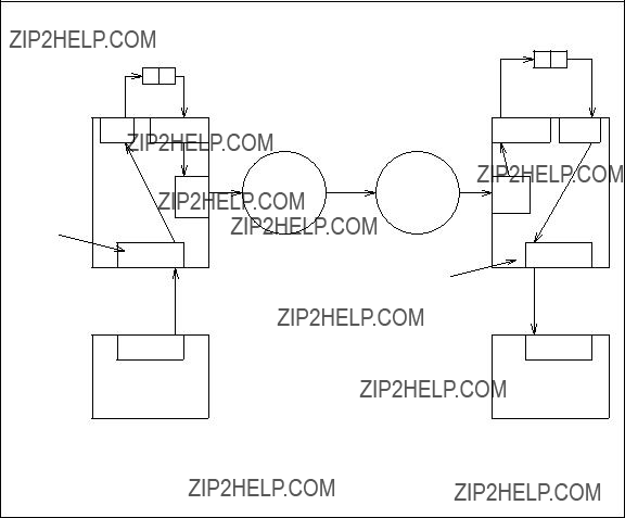
________________________________________________________________________________________________
________________________________________________________________________________________________
SYSTEM : TRANSLATION :
MACHINE : AUDIX FORM:
MACHINE NAME AUDIX2
DIAL STRING 9+5387000
MAINTENANCE : NETWORK FORM:
CONNECT TO AUDIX2
NOTE:
Dotted facilities imply that they are not used for this particular call
Figure

_______________________________________________________________________________________
_______________________________________________________________________________________
SYSTEM : TRANSLATION :
MACHINE : AUDIX FORM:
MACHINE NAME AUDIX2
DIAL STRING 7000
MAINTENANCE : NETWORK FORM:
CONNECT TO AUDIX2
NOTE:
This ???gure shows the TN539 (ACCE) in use, although not required for
this particualr network
Figure

________________________________________________________________________________________________
________________________________________________________________________________________________
Step 1B: Testing Remote Switched
This test involves a path similar to Figure
NOTE
Connection and modem
1.Go to the system : translation : machine : audix/amis/call delivery form. Set machine name to the name of the AUDIX system to be called using the
has not been assigned. Go to Chapter 13, AUDIX System Administration, and create the remote system pro???le.
2.The network data phone number (or dial string) must contain ATDT (the modem attention code), the central of???ce (CO) access code, a comma as a pause, and the Direct Inward Dialing (DID) number associated with that AUDIX system???s network hunt group.
3.Go to the system : translation : network port form. Make sure a valid modem initialization string is assigned for the channel you want to test. See Chapter 13 if you are unsure as to what should be assigned.
4.Go to the maintenance : network form. Make sure the channel you want to test is idle. In most cases either
5.Go to select test and enter 1.
6. Go to machine name and enter the name of the other AUDIX system. Press CHANGE or RUN . Wait for the result. If the test is not successful, check the system : log and/or go to Flowcharts For Troubleshooting the Network.
_______________________________________________________________________________________
_______________________________________________________________________________________
SYSTEM : TRANSLATION :
MACHINE : AUDIX FORM:
MACHINE NAME AUDIX2
DIAL STRING ATDT 9+4527000
MAINTENANCE : NETWORK FORM:
CONNECT TO AUDIX2
Figure
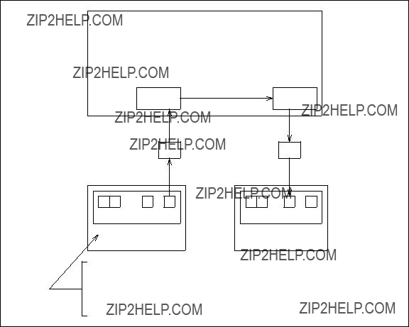
________________________________________________________________________________________________
________________________________________________________________________________________________
SYSTEM : TRANSLATION :
MACHINE : AUDIX FORM:
MACHINE NAME AUDIX2
DIAL STRING (BLANK)
MAINTENANCE : NETWORK FORM:
CONNECT TO AUDIX 2
Figure

_______________________________________________________________________________________
_______________________________________________________________________________________
Step 1C: Testing Remote Switched
This test involves a path similar to Figure
1. Go to the system : translation : machine : audix/amis/call delivery form. Set machine name to the name of the remote AUDIX system. Press ENTER . The remote AUDIX system???s machine pro???le should be displayed. If it is not displayed, it has not been assigned. Go to Chapter 13, AUDIX System Administration, and create the remote system pro???le.
2.The network connection channel (or channel) should be blank unless channel 5 or channel 6 must be used for the call (in which case, enter the channel number).
3. The network data phone number (or dial string) should be blank. Press CHANGE or RUN if any changes were made.
4. Go to the system : translation : network port form. Make sure the switched/dedicated ???eld for the channel(s) is set to s. Press 
 if any changes were made.
5.Go to the maintenance : network form. Make sure the channel to be tested is idle.
6.Go to select test and enter 1.
7. Go to machine name and enter the name of the remote AUDIX system. Press CHANGE or RUN . Wait for the result. If the test is not successful, check the system : log and/or go to Flowcharts For Troubleshooting the Network.

________________________________________________________________________________________________
________________________________________________________________________________________________
SYSTEM : TRANSLATION :
MACHINE : AUDIX FORM:
MACHINE NAME AUDIX2
DIAL STRING 9+4527000
MAINTENANCE : NETWORK FORM:
CONNECT TO AUDIX2
NOTE:
For low speed,
a data module used for outgoing calls must be a 7400A/B module. 7400A/B and MPDMs can be used for low speed incoming calls.
For high speed, an MPDM/M1* is required, (incoming only ??? no outgoing calls supported).
Figure

_______________________________________________________________________________________
_______________________________________________________________________________________
Step 1D: Testing Remote Dedicated
This test involves a path similar to Figure
1. Go to the system : translation : machine : audix/amis/call delivery form. Set machine name to the name of the other AUDIX system. Press ENTER . The other AUDIX system???s machine pro???le should be displayed. If it is not displayed, it has not been assigned. Go to Chapter 13, AUDIX System Administration, and create the remote system pro???le.
2.The network connection channel (or channel) should be set to the number of the channel that is cabled to the other AUDIX system. In Figure
3. The network data phone number (or dial string) should be blank. Press CHANGE or RUN if any changes were made.
4.Go to the maintenance : network form. Make sure the channel to be tested is idle.
5.Go to select test and enter 1.
6. Go to machine name and enter the name of the other AUDIX system. Press CHANGE or RUN . Wait for the result. If the test is not successful, check the system : log and/or go to Flowcharts For Troubleshooting the Network.

________________________________________________________________________________________________
________________________________________________________________________________________________
SYSTEM : TRANSLATION :
MACHINE : AUDIX FORM:
MACHINE NAME AUDIX2
DIAL STRING (BLANK)
MAINTENANCE : NETWORK FORM:
CONNECT TO AUDIX2
Figure

_______________________________________________________________________________________
_______________________________________________________________________________________
Step 2: Performing
If the appropriate test in Step 1 fails, perform the appropriate
???
???Local connection test
???Network
???Network
Step 2A: Testing the
This tests the loop shown in Figure
2.The network data phone number (or dial string) must be the CO or network access code, a pause, and the DID number associated with the local network hunt group.
a.Use a plus sign as a pause if testing DCP channels.
b.Use a comma as a pause if testing
3.If a change was required, press CHANGE or RUN , exit the form and go to the maintenance : audits : fp form. Run a network data audit. This is necessary for R1V3 and R1V4 systems only; it is not necessary for R1V5 and later systems.
4.Go to the maintenance : network form.
Set select test to 1. Set machine name to the name of the local AUDIX system. Press
CHANGE or RUN . Wait for the result. If the test is not successful, check the system : log and/or go to Flowcharts For Troubleshooting the Network.

________________________________________________________________________________________________
________________________________________________________________________________________________
SYSTEM : TRANSLATION :
MACHINE : AUDIX FORM:
NETWORK
SWITCH
. . . . . . . . . . . . . . . . . . . . . . . . .
MACHINE NAME AUDIX1
DIAL STRING 9+4526000
MAINTENANCE : NETWORK FORM:
CONNECT TO AUDIX1
NOTE:
Dotted facilities implies that they are not used for this particular call
Figure

_______________________________________________________________________________________
_______________________________________________________________________________________
SYSTEM : TRANSLATION :
MACHINE : AUDIX FORM:
MACHINE NAME AUDIX1 DIAL STRING 9+4526000
MAINTENANCE : NETWORK FORM:
CONNECT TO AUDIX1
. . . . . . . . . . . . . . . . . . . . . . .
Figure
Note that in Figure

________________________________________________________________________________________________
________________________________________________________________________________________________
. . . . . . . . . . . . . . . . . . . . . . . . . . . .
Figure
_______________________________________________________________________________________
_______________________________________________________________________________________
Step 2B: Testing the Local Connection
This tests the loop shown in Figure
1. Go to the system : translation : machine : audix/amis/call delivery form and press ENTER . The local machine pro???le should be displayed.
2.Make sure the network data phone number (or dial string) includes only the extension number assigned to the networking hunt group. If using switched

________________________________________________________________________________________________
________________________________________________________________________________________________
SYSTEM 85
OFFICE
CODE 452
EXTENSION
6000
NETWORK . . . . . . . . . . .
SWITCH
NETWORK
SWITCH
DCP
ACC
AUDIX 1
These channels are not necessarily the channels used for the test call
. . . . . . . . . . . . . . . . . . . . . . . . .
SYSTEM : TRANSLATION :
MACHINE : AUDIX FORM:
MACHINE NAME AUDIX1
DIAL STRING 6000
MAINTENANCE : NETWORK FORM:
CONNECT TO AUDIX1
Figure

_______________________________________________________________________________________
_______________________________________________________________________________________
SYSTEM : TRANSLATION :
MACHINE : AUDIX FORM:
MACHINE NAME AUDIX1
DIAL STRING ATDT 6000
MAINTENANCE : NETWORK FORM:
CONNECT TO AUDIX1
Figure

________________________________________________________________________________________________
________________________________________________________________________________________________
SYSTEM : TRANSLATION :
MACHINE : AUDIX FORM:
MACHINE NAME AUDIX1
DIAL STRING (BLANK)
MAINTENANCE : NETWORK FORM:
CONNECT TO AUDIX1
Figure

_______________________________________________________________________________________
_______________________________________________________________________________________
Step 2C: Testing the 56/64 Kbps Network Connection
This tests the connection between the local AUDIX system and a 56 Kbps or 64 Kbps serving of???ce (SO), as shown in Figure
While a channel is in loopback mode, it will be unavailable to send information to remote systems or receive information from remote systems. Also, if you put a channel in loopback mode, any active calls will be dropped. It is therefore recommended that before you perform this test you check the status of the channel. It is also not a good idea to perform this test during peak traf???c times.
1. Go to the maintenance : network form. Set select test to 7 for to test a 56 Kbps network
NOTE
To test channel 5 or 6
2.Have the serving of???ce place a call to the telephone number assigned to the channel you speci???ed on the maintenance : network form. If the test is successful, any data the serving of???ce sends over the AUDIX channel will be echoed back.
3.Go to the maintenance : network form. Set select test to 9 to take the channel out of
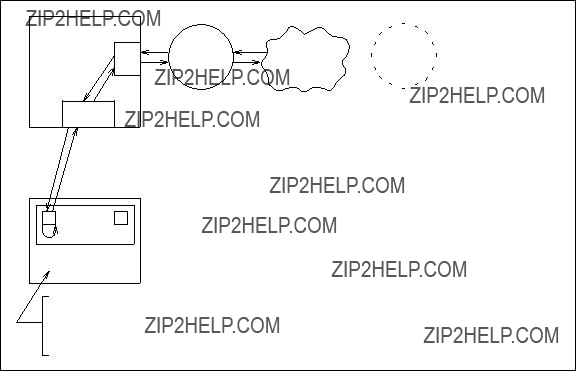
________________________________________________________________________________________________
________________________________________________________________________________________________
SYSTEM 85
DCP
POINT-
OF-
PRESENCE
SWITCH
. . . . . . . . . . . . . . . . . . . . . . . . .
MAINTENANCE: NETWORK FORM:
NETWORK LOOPAROUND START 56/64 Kbps
Figure

_______________________________________________________________________________________
_______________________________________________________________________________________
Step 3: Performing Channel or Modem
If the appropriate tests in step one and step two fail, perform the appropriate test:
???Channel internal
???Modem
Step 3A: Channel Internal
This test is used to verify the operation of an individual channel on the ACC or ACCE board. No connection (that is, no call) is needed for this test.
1.Go to the maintenance : network form.
2.Set select test to 2.
3. Go to channel and enter 1, 2, 3, or 4. Press CHANGE or RUN . Wait for the result. If the test is not successful, check the system : log and/or go to Flowcharts For Troubleshooting the Network.
Use the modem
NOTE
Step 3B: Modem
This test is only for modems connected to the
1.If you are not using a MICROCOM QX 3296/C modem, go to step 2. If you are testing a MICROCOM QX 3296/C modem, you must ???rst go to the system : translation : network port form. Record the three data rate ???elds and the modem initialization string ???eld for the channel to be tested. These values will be restored once the test is completed. Now change the data rate ???elds to 2400 and change the modem initialization string ???eld to AT\n0. Press
CHANGE or RUN .
2. Go to the maintenance : network form. Set select test to 6. Set channel to 5 or 6. Press
CHANGE or RUN . Wait for the result. If the test is not successful, check the system : log and/or
go to Flowcharts For Troubleshooting the Network.
3.If you are testing a 3296/C, go back to the system : translation : network port and restore the original translations.

________________________________________________________________________________________________
________________________________________________________________________________________________
SETTING UP REMOTE UPDATES
Before activating the Remote Updates feature, check to see if calls between systems are toll calls. Also, check the number of subscribers that already exist (traffic : feature : day form). If there are much more than 100 local subscribers, the customer may want to wait for a low traf???c period and/or discount calling time before updates are activated.
Step 1: Activating the Remote Updates Feature
Perform the following steps to activate remote updates. To start with, activate remote updates only between the local AUDIX machine and one remote machine.
5.For R1V3 and R1V4 systems only: Go to the maintenance : audits : fp form and run a network data audit. (This step is not necessary for R1V5 and later systems.)
6.Repeat steps 1 through 5 at the remote system you selected in step 4. Note that the ??????remote?????? system becomes the ??????local?????? system once you log in to it.
Step 2: Testing the Remote Updates Feature
Demand Update Procedure
This procedure will cause a full update from the speci???ed system only.
2.Go to the maintenance : network form and perform a connection test to the system speci???ed in step 1. If this is the ???rst remote update from this system, the connect test could take a long time if there are a large number of subscriber records to be sent.
3.Once the connect test has completed, go to Log In to the Remote Adjunct.
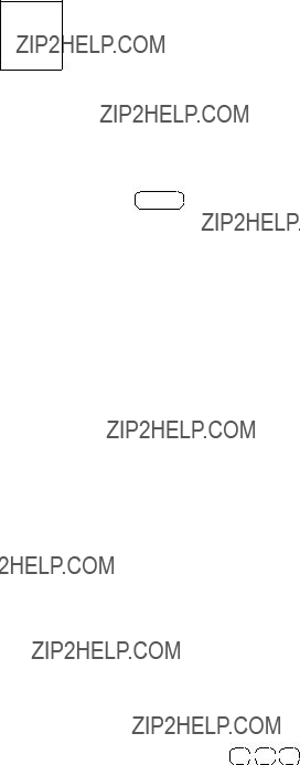
_______________________________________________________________________________________
_______________________________________________________________________________________
Log In to the Remote Adjunct
1.After the automatic or demand update has completed, log in to the remote system and check the list : extension : remote form to see if the subscribers from the local system are now identi???ed by the remote system.
NOTE
You can also check the number of remote and
Check the type ???eld. If any of the subscribers are type v (veri???ed) or are type u (unknown), there may be a minor problem. Most likely the subscriber(s) extension and/or name is duplicated somewhere in the network. Check the following:
a.The subscriber???s extension must be within the address range of their local AUDIX system.
b.Go to the subscriber : remote form, enter the subscriber name or extension/machine
name, and press ENTER . See if more than one machine name is listed. If so, the subscriber cannot be pinpointed to a single AUDIX system. Check for the appearance of the extension at multiple systems. Also, see if the subscriber???s alphanumeric name on the subscriber : local form matches another subscriber???s name. Keep in mind that the alphanumeric pattern is converted to a
c.At the remote AUDIX system, check the administrator???s log to see if the subscriber has a ??????name not recorded?????? entry. If so, record the name. The update facility, at the scheduled interval, will then transmit the change to the other AUDIX systems and will change the subscriber status to administered .
d.At the remote AUDIX system, see if the subscriber has a valid profile (subscriber : local).
e.See if the number of subscribers being added to the system (both local and remote) exceeds the limit assigned on the system : limits form.
2.Repeat step 2 at the local system to see that the subscribers at the remote system are now identi???ed at the local system.
Step 3: Performing Voice Mail Test
1.At the Local Switch, create a message and manually address it to remote subscribers as follows:
a.Log in to the AUDIX system and create a message such as ??????I am testing manual addressing to remote subscribers. Please call me to verify that you have received the message.?????? The message header will tell them who to call.
b.When requested to enter an extension, enter a remote subscriber address as speci???ed on the system : translation : machine : audix/amis/call delivery form, followed by #. Enter one remote subscriber from each remote switch.
c. When ???nished addressing, press * 
 *
* 
 # for immediate delivery.

________________________________________________________________________________________________
________________________________________________________________________________________________
d.From the main activity menu, press option 4 to check the status of the message delivery.
???At this point, the status will be
???After the message has been delivered to the remote AUDIX system, the status will be ??????DELIVERED.??????
???After the remote subscriber has heard the message, the status will be ??????DELIVERED??? ACCESSED.??????
2.At the remote switch, have the remote subscribers verify the following:
a.Their MESSAGE lamp is lit.
b.When they log in to the AUDIX system, the message header includes the AUDIX machine name (if assigned) and the subscriber ID.
3.At the Local Switch, repeat steps 1 and 2 only this time use a mailing list as follows:
a.Log in to the AUDIX system and create a mailing list. Include a subscriber from each AUDIX system.
b.Create a message and address it to the mailing list. The message should include something like ??????I am testing list addressing to remote subscribers. Please call me to verify that you have received the message.??????
c. When ???nished, press * 
 *
* 
 # for immediate delivery.
d.Press option 4 to check the status of the message delivery.
e.Have the remote subscribers check for new messages.
4.Repeat Steps 1, 2, and 3 at each of the AUDIX systems in the network.
Step 4: Activating Remote Updates for Additional AUDIX Systems
1.If everything went okay in the previous procedures, add a third system to the remote updates facility. You will then have three machine pro???les on three different systems with the Remote Updates feature active.
2.The next scheduled transmission interval at each AUDIX system will cause an update at the other two AUDIX systems. If done during
3.Check each system for the appearance of two sets of remote subscribers.
4.Run test calls to/from the newly added system.
5.If everything went okay, add additional systems one at a time.
_______________________________________________________________________________________
_______________________________________________________________________________________
CHECKING ADMINISTRATION LOG ENTRIES
The system administrator???s log can be found on the system : log form. The following entries may appear in this log to help solve network connect failures. There are other entries not shown here that report other areas of concern such as a subscriber that has no name recorded.
???One of these entries may occur when the local system rejects an incoming network call from another system (TN539 or TN539B ACCE only):
?????????Rejected login from remote machine machine name - invalid password??????
?????????Rejected login from remote machine machine name - unknown machine name??????
?????????Rejected login from remote machine machine name?????? (This entry means the call was rejected for some other reason.)
???One of these entries may occur when the local system has an outgoing network call to another system rejected (TN539 or TN539B ACCE only):
?????????Connect to machine machine name aborted - invalid machine name??????
?????????Connect to machine machine name aborted - invalid password??????
?????????Connect to machine machine name aborted - permission denied??????
?????????Connect failure to machine machine name?????? (see NOTE)
(This entry means that there was a problem at the switch: no dial tone, no ringing, busy, dial denied, try again, no carrier, no answer, answered - no response, no resources, protocol handshake failure, premature hang up, or some other reason.)
?????????Continuing connect failure to machine machine name?????? (see NOTE)
???One of these entries may occur when the local system has an outgoing network call to another system rejected (TN366 or TN366B only):
?????????Machine machine name rejected login??????
?????????Connect failure to machine machine name?????? (see NOTE)
?????????Continuing connect failure to machine machine name?????? (see NOTE)
NOTE
The called system will reject a network call if it is very low on voice message space. Local subscribers are given preference over incoming networked messages if disk space is low.
________________________________________________________________________________________________
________________________________________________________________________________________________
TROUBLESHOOTING THE NETWORK
These ???owcharts should help you to troubleshoot the network when you get a ??????failed?????? result for one of the tests. The system : log form might also help with troubleshooting the network. A list of network- related entries in this log are provided in the previous section, Administration Log Entries for Networking. Test procedures can also be found under Testing the Initial Setup of the Network.

Figure
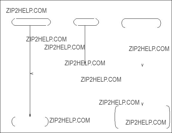
________________________________________________________________________________________________
________________________________________________________________________________________________
AUDIX CHANNEL STATUS (SEE FIGURE
Figure
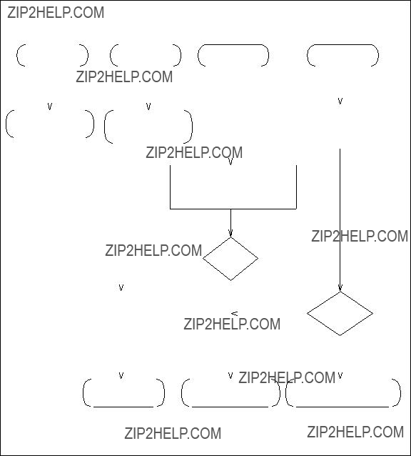
_______________________________________________________________________________________
_______________________________________________________________________________________
AUDIX CHANNEL STATUS (SEE ALSO FIGURE
RUN CHANNEL INTERNAL
MAINT : NET FORM
NOTE:
For AUDIX R1V3 or later,
channels 2 and 4 on Generic 1, Generic 3, or System 75 will always be DOWN. Channels 1 and 3 on a MERLIN II will always be DOWN.
Figure
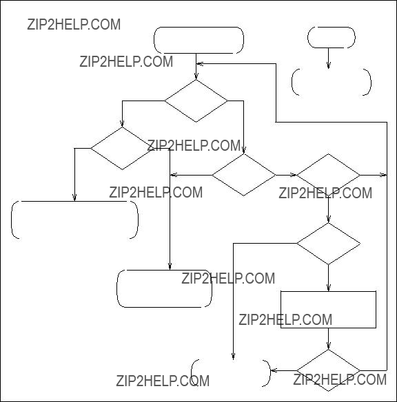
Figure

Figure

Figure

Figure

________________________________________________________________________________________________
________________________________________________________________________________________________
Figure
_______________________________________________________________________________________
_______________________________________________________________________________________
REMOTE CONNECTION FAILURE
FAILED/BUSY/
NO ANSWER
REMOTE
TRANSLATIONS
REJECT
CHECK REMOTE ID
AND PASSWORD
NO
GO TO REMOTE
NO
OK?
YES
MORE
CONNECTION TEST
NO
CORRECT
*NOTE:
"N" depends on how busy your network is and how much time you can devote to this test.
THAN ??????N??????
TIMES?*
YES
NO OTHER
REMOTES
FAIL?
FACILITIES
TO THE REMOTE
OK?
YES
ON REMOTE
CHECK NEAR END
CONNECT FAILURE
YES
Figure
________________________________________________________________________________________________
________________________________________________________________________________________________

A. Network Considerations
_______________________________________________________________________________________
_______________________________________________________________________________________
This appendix is targeted for the Business Communications Systems Design Center (BCSDC). Appendix B, Sales Engineering Notes, contains the information that must be completed by the account team and sent to the BCSDC. Every AUDIX Networking installation must be engineered by the BCSDC.
NOTE
The information in this appendix may also be useful to the AUDIX Networking coordinator. The worksheet provided in this appendix should help the coordinator with equipment assignments and extension numbers.
BCSDC CONSIDERATIONS
The BCSDC should consider the following:
???AUDIX and Switch Equipment: See Chapters 1 through 7 for AUDIX system and switch requirements for each particular setup.
???Disk Drive Capacities: When an AUDIX system is networked with another AUDIX system, additional demands may be placed on the storage devices. Each AUDIX system is not only asked to store the names, pro???les, and messages of its local subscribers, but also the names, pro???les, and messages from remote subscribers.
Also, whenever a message is addressed to a remote subscriber, the message is placed in a queue until it can be sent to the remote machine. If the transmission interval is set to deliver remote messages only once or twice a day, the queue area of a particular machine may be asked to store up to 150 messages. Once this limit is reached, a connection to that machine is attempted in order to transmit the messages in queue.
???Trunking: AUDIX R1V6 or later software can support up to six network calls at one time (provided the system has a TN539 vintage 7 or a TN539B ACCE). However, an AUDIX R1V6 or later system connected to a System 75, System 75 XE, DEFINITY Generic 1 or Generic 3, or MERLIN II network can only support four simultaneous calls (two DCP and two
AUDIX R1V5 systems can support four simultaneous calls no matter what switch is used, provided the system has the TN539 or TN539B with six ports (with MERLIN II networking this is assuming two
With that in mind, new trunk circuits may or may not be required between switches in the network. AUDIX system traf???c may be able to share existing trunk circuits with other types of
???The con???guration of the network (see Figure
???Does the customer intend on using AUDIX system remote updates feature? If so, and this is generally the case, only a slight additional load is placed on the networking links once the initial exchange of subscriber data is made.

________________________________________________________________________________________________
________________________________________________________________________________________________
???What networking transmission interval is selected (that is, the amount of time between scheduled calls to other systems for passing messages). Does the customer want several short calls spread out during the day or one or two longer calls made during
???The amount of voice mail typically addressed to remote subscribers.
???The typical length of these remotely addressed messages.
???Administration: Each AUDIX system and each switch in the network requires administration. Once you have determined how the network should be con???gured, give the information to the coordinator (appointed by the customer and/or AT&T representative) who will make sure each step of the order is completed successfully. This will make troubleshooting of any problems simpler. The steps are:
1.Install, assign, and test the switch for any newly required trunk facilities. This may include modem pooling. Facilities administration may cause service interruptions. For example, if the Alternate Voice/Data (AV/D) bit needs to be set for a Data Services 1 (DS1) trunk group, all trunks must be removed from the group, the group deleted, and everything added back (with AV/D now activated).
2.Install, assign, and test the AUDIX system(s) for local service. This usually requires data link administration which may cause service interruption of other features such as Call Management System (CMS), Distributed Communications Service (DCS), and Message Center. If the AUDIX Communications Controller (ACC) board is already installed, busy out its channels so the system does not acknowledge them until the network is installed. If the ACC is not installed, leave it out until after the AUDIX network is installed.
The network channels must be busied out after any reboot.
NOTE
3.Assign the AUDIX systems for networking service one at a time.
???Communities of interest: Whenever possible, it is recommended that an entire community of interest be administered on a single AUDIX system. Communities of interest consist of subscribers who will exchange messages frequently (for instance people in the same department or working on the same project).
This arrangement is not required, but by keeping all members of a community of interest on the same machine, remote message traf???c could be reduced. Also, remote message throughput could be increased and remote message delivery times could be decreased.

_______________________________________________________________________________________
_______________________________________________________________________________________
AUDIX
E
AT&T
SWITCH
Figure
________________________________________________________________________________________________
________________________________________________________________________________________________
AUDIX NETWORK PLANNING WORKSHEET
Network Coordinator: Fill out one of the following worksheets for each AUDIX system in the network. Then give the set of worksheets to the account team or the technician to be used to set up and administer the AUDIX network correctly. This section provides an explanation of each ???eld.
NOTE: Keep this worksheet as a master copy. Make copies for each AUDIX system.


________________________________________________________________________________________________
________________________________________________________________________________________________
________________________________________________________________________________________________
________________________________________________________________________________________________
UPGRADES, SOFTWARE, AND VINTAGES
It is a Marketing responsibility to verify that correct software exists in both the Private Branch Exchange (PBX) and the AUDIX system and that correct vintages of circuit packs exist in the AUDIX system to accommodate any added features. For example, a Distributed Communications System (DCS) environment with more than ???ve PBXs in the cluster will require checking if the TN533 SCPI is the correct vintage. Use the maintenance : system : vintage form documented in the appropriate AUDIX forms reference manual to determine required minimum vintages.
________________________________________________________________________________________________
________________________________________________________________________________________________
________________________________________________________________________________________________
________________________________________________________________________________________________
Abbreviations
_______________________________________________________________________________________
_______________________________________________________________________________________
________________________________________________________________________________________________
________________________________________________________________________________________________
________________________________________________________________________________________________
________________________________________________________________________________________________
Glossary
_______________________________________________________________________________________
_______________________________________________________________________________________
________________________________________________________________________________________________
________________________________________________________________________________________________

Glossary
_______________________________________________________________________________________
_______________________________________________________________________________________

Glossary
_______________________________________________________________________________________
_______________________________________________________________________________________
________________________________________________________________________________________________
________________________________________________________________________________________________
Index
_______________________________________________________________________________________
_______________________________________________________________________________________
________________________________________________________________________________________________
________________________________________________________________________________________________
U
UN160B
complete
demand procedure
V
voice ID
W
worksheet administrator

