AT&T
Universal Paging Access Module Kit
Installation Manual
Document No.
AT&T
Universal Paging Access Module Kit
Installation Manual
Document No.
To Order Copies of This Manual:
Your AT&T Information Systems Sales Representative
or
Call:Your Business Sales and Service Center
or
The AT&T Customer Information Center,
AT&T Customer Information Center
Write:P.O. Box 19901
Indianapolis, IN 46219
Order:Document Number
For Technical Assistance Call :
GBS Technical Support
Limited Warranty and Limitation of Liability
AT&T warrants to you that the product will be free from defects in material and workmanship when title passes to you. If you notify AT&T that the product has failed to operate as warranted within one year of the date title passes to you, AT&T will, at its option, repair or replace the component or components of the product that failed to operate as warranted. Any repair or replacement components may be new or refurbished and will be provided on an exchange basis. If AT&T determines that the product cannot be repaired or replaced, AT&T will refund the purchase price to you.
If you purchase the product directly from AT&T, AT&T will perform warranty repair on your premises in accordance with the terms and conditions of AT&T???s ???Business Day??? or
The limited warranties provided above do not cover damages, defects, malfunctions or product failures caused by:
???Failure to follow AT&T???s installation, operation or maintenance instructions;
???Unauthorized modification or alteration of the product or its components;
???Product abuse, misuse or the negligent acts of persons not under the reasonable control of AT&T;
???Actions of third parties and acts of God other than power surges (e.g., lightning).
This limited warranty applies only to the product purchased directly from AT&T or purchased directly from an authorized AT&T dealer. This limited warranty does not apply to products purchased or operated outside the United States.
You may be required to provide AT&T with proof of purchase before AT&T will perform any warranty replacements.
EXCEPT AS SPECIFICALLY SET FORTH ABOVE, AT&T, ITS AFFILIATES, SUPPLIERS AND DEALERS MAKE NO
WARRANTIES, EXPRESS OR IMPLIED, AND SPECIFICALLY DISCLAIM ANY WARRANTY OF MERCHANTABILITY
OR FITNESS FOR A PARTICULAR PURPOSE.
EXCEPT FOR PERSONAL INJURY, THE LIABILITY OF AT&T, ITS AFFILIATES, SUPPLIERS AND DEALERS FOR
ANY CLAIM, LOSS, DAMAGE OR EXPENSE FROM ANY CAUSE WHATSOEVER, REGARDLESS OF THE FORM
OF THE ACTION, WHETHER IN CONTRACT, TORT OR OTHERWISE, SHALL NOT EXCEED THE LESSER OF
DIRECT DAMAGES PROVEN OR THE REPAIR OR REPLACEMENT COST OF THE SYSTEM OR THE SYSTEM???S
PURCHASE PRICE. IN NO EVENT SHALL AT&T, ITS AFFILIATES, SUPPLIERS AND DEALERS BE LIABLE FOR
INCIDENTAL, RELIANCE, CONSEQUENTIAL OR ANY OTHER INDIRECT LOSS OR DAMAGE (INCLUDING LOST
PROFITS OR REVENUES SUSTAINED OR INCURRED IN CONNECTION WITH THE SYSTEM). THIS LIMITATION
OF LIABILITY SHALL SURVIVE FAILURE OF THE EXCLUSIVE REMEDY SET FORTH IN THE LIMITED WARRANTY
ABOVE.

AT&T
Universal Paging Access Module
Installation Manual
Issue 2, June 1990
Bogen Part No.
Printed in U.S.A. 9006
Federal Communications Commission (FCC) Statement (Part 68)
This equipment is component registered with the Federal Communications Commission (FCC) in accordance with Part 68 of its rules. In compliance with the rules, be advised of the following:
Registered equipment may not be used with Coin Telephone Lines. Equipment may be used with Party Lines in areas where state tariffs permit such connections and when equipment is adaptable for such service.
This equipment is registered as follows:
Registration Number -
Ringer Equivalence - 1.2B
If trouble is experienced, the equipment should be disconnected from the interface to determine if this equipment, or the telephone line is the trouble source. If the equipment is determined to be malfunctioning, it should not be reconnected until repairs are effected.
Repairs to this equipment, other than routine repairs, can be made only by the manufacturer or its authorized agents.
If the equipment causes harm to the telephone network, the local telephone company may temporarily discontinue your service and, if possible, notify you in advance. If advance notice is not practical, you will be notified as soon as possible. You will be given the opportunity to correct the problem and informed of your right to file a complaint with the FCC.
The local telephone company may make changes in its facilities, operations, or procedures that could affect the proper functioning of your equipment. If they do, you will be given adequate notice in writing to allow you an opportunity to maintain uninterrupted telephone service.
Table of Contents

1.Product Identification
The
Overview
The Model
RCA jack to phone jack adaptor RCA jack to
Features
???Acts as point of demarcation
Acts as a point of demarcation between telephone system and customer paging equipment.
???24V or 48V operation (trunk port operation)
Mode switches let you select
???Preannounce and Confirmation Tones
A preannounce tone (heard at the telephone and the loudspeakers) or confirmation tone (heard only at the telephone) can be selected with mode switches (one of these modes must be selected for the unit to operate properly). A
(Note: when used with
???VOX Delay Timer
Voice controlled disconnect timer, for use in station port operation is enabled with a mode switch. This automatically disconnects the line after a predetermined interval of silence (from 2 to 6 seconds, set with the VOX DELAY control; the setting may be critical with telephone systems that issue a rapid reorder tone after the paging party hangs up).
???Default Timer
A default timer sets the maximum time allotment for paging (6 to 35 seconds, set with the PAGING TIME control). This timer ensures that the unit will always disengage the line by forcing a disconnect, if the other disconnect functions are disabled or not available with a specific telephone switch.
Note: The timer may be inhibited; see Default Timer Modifications on page 9 for procedure.
???Background music input jack and volume control
An
???Contact Closures
Two
???Direct connection to page ports through a modular jack on the side of the unit
An

Important Power Supply Note
One of two types of power supply are shipped with the
Note: the order of the terminals differs from one supply to the other. Be sure to observe correct polarity when connecting power supply.
117V
200 mA
60 Hz
117 V
200 MA 60HZ
CAUTION: INDOOR USE ONLY IN
A CONTROLLED ENVIRONMENT
MODEL
CLASS 2 POWER SUPPLY
CAUTION: FOR INDOOR USE ONLY

2.Connection to the Telephone System
General Instructions
This section contains installation procedures for connection to the telephone system. You should first follow the General Instructions and then refer to the Specific Instructions for the type of telephone switch to be connected (loop- or
You will need the following tools for installation: standard
Select location and physical installation
The UPAM may be mounted on a wall or backboard. It can be located either in close proximity to the telephone equipment (a modular cord is included and can be used to connect the unit to the telephone system) or near the paging equipment. To install the unit using the keyhole slots, install two screws (not included) with a
Grounding
The UPAM is designed with protection devices which are intended to shunt to ground any excess (surge) voltage appearing on the Tip and Ring input pair. The metal case of the UPAM must be grounded to a ground shorting bar, if available, or to a suitable electrical (earth) ground. Connect a ground wire (with a
Mode switches
A set of 5 mode switches (S1 through S5, see the illustration on the previous page) is included to set the power supply voltage, confirmation or preannounce tone, and VOX operation. These switches are accessible through an opening in the front cover and can be moved with a pointed tool, such as the tip of a ball point pen. Set the switches as described in the Specific Instructions, which follow.
Power supply connections
No power supply is required when the UPAM is connected to a PABX station port (supplying analog ring voltage and approximately
Internal adjustments
Certain options are available (described in Specific Instructions section) which require the removal of the cover and the modification of certain components. The illustrations on page 11 show the different revision levels of the printed circuit boards used, and identify the location of the important components.
A small parts bag is located under the cover, either taped to the inside of the cover or wedged between the case and a large capacitor in the upper
Paging system connections
Illustrations showing connection of the UPAM to a typical paging system are included in the third section of this manual. If you need more information about paging systems, consult the UPAM CPE Reference Guide, available from AT&T.
Troubleshooting
A Functional Test Guide in Section 4 isolates problem areas, if they arise, following installation.

Specific Instructions
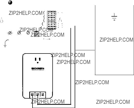
Trunk Port Connections ??? Loop Start
Controls for VOX Delay, Page Time, and Mode Switch S5 are not operable in this mode.
Procedure
1.Mount and ground the UPAM as described in the General Instructions.
2.Set mode switches S1 and S2 in OFF position for use with the
3.Set mode switches S3 and S4 for Preannounce or Confirmation tone (as desired).
4.Connect ???Tip??? of trunk port toT terminal on UPAM.
5.Connect ???Ring??? of trunk port toR terminal on UPAM.
6.Connect PT and PR terminals on UPAM to the paging system, as shown in Section 3. Also, connect any background music source to the BGM IN jack on the UPAM.
7.Connect power supply + and - terminals to the +24V/48V and
8.Call the system and adjust the volume of the page using the paging system???s amplifier volume control.
9.Hang up and adjust the background music level using the UPAM BGM VOL control.
10.Call the system and adjust the volume of the preannounce/confirmation tone, using the UPAM TONE
VOL control.
405899972
MODEL
CAUTION: FOR INDOOR USE ONLY
Trunk Port Connections ??? Loop Start
Specific Instructions
Trunk Port Connections ??? Ground Start
Controls for VOX Delay, Page Time, and Mode Switch S5 are not operable in this mode.
Procedure
1.Mount and ground the UPAM as described in General Instructions.
2.Set mode switches S1 and S2 in OFF position for use with the
3.Set mode switch S3 to ON position and S4 to OFF position (see Note 1).
4.Connect a jumper wire between N.O. and T terminals on UPAM.
5.Connect ???Tip??? of trunk port toCOM terminal on UPAM.
6.Connect ???Ring??? of trunk port toR terminal on UPAM.
7.Connect PT and PR terminals on UPAM to the paging system, as shown in Section 3. Also, connect any background music source to the BGM IN jack on the UPAM.
8.Connect UPAM +24/48V terminal to PBX ground (see Note 2).
9.Connect power supply + and - terminals to +24V/48V and
10.Call the system and adjust the volume of the page using the paging system???s amplifier volume control.
11.Hang up and adjust the background music level using UPAM BGM VOL control.
12.Call the system and adjust the volume of the preannounce tone using UPAM TONE VOL control.
Notes:
1.Only preannounce tone is available for ground start trunk applications.
2.Usually the AC GND terminal on the 48 volt power supply included can be used to provide this connection.
405899972
MODEL
CAUTION: FOR INDOOR USE ONLY
48 V
200mA AC
+- GND
Trunk Port Connections ??? Ground Start
Specific Instructions
Station Port/Centrex Connections
Disconnect methods
In station port operation, the UPAM provides CPC ???
Procedure
No power supply is used for Station Port/Centrex operation.
1.Mount and the ground the UPAM as described in General Instructions.
2.Set mode switches S3 and S4 for Preannounce or Confirmation tone (as desired).
One of these modes must be selected for UPAM to operate correctly.
3.Place mode switch S5 in the Off position.
4.Connect ???Tip??? of station port toT terminal of UPAM.
5.Connect ???Ring??? of station port toR terminal of UPAM.
6.Connect PT and PR terminals on UPAM to the paging system, as shown in Section 3. Also, connect any background music source to the BGM IN jack on the UPAM.
7.Set the Default Timer by calling the system, and measuring the length of time before the call is disconnected. Adjust the PAGING TIME control and repeat and readjust as necessary.
8.Call system and set the page volume using the paging system???s amplifier volume control.
9.Hang up and adjust the background music level using UPAM BGM VOL control.
10.Call the system and adjust the volume of the preannounce/confirmation tone volume using the TONE VOL control. (Note: If the tone can be heard over the paging system but is shortened, or if it is absent in the handset, it may be necessary to increase the length of ring before the UPAM answers. See Ring Delay on page 10.)
11If the VOX disconnect is to be used, adjust the VOX delay. To do this, make sure mode switch S5 is in the ON position and proceed as follows:
11.1Rotate VOX DELAY control approximately 1/2 way.
11.2Call the system and, after the preannounce or confirmation tone, speak into the telephone for 5 seconds at a normal voice level then stop and evaluate the time delay before disconnection. If it is sufficiently long to allow for pauses in phrases without disconnecting, proceed to the next step. If necessary, readjust VOX DELAY and repeat step.
Note: The minimum VOX delay is approximately 2 seconds. On some systems, which return a reorder tone to the called party within 2 seconds of hang up, VOX DELAY cannot be used.

Default Timer Modifications
Inhibit default timer
A field modification is available to inhibit the default timer. Do not inhibit the timer if jumpers J2 & J3 have been removed as outlined in Important Centrex Modification, below, and the VOX delay timer has been disabled (S5 is OFF). This situation may cause the UPAM to remain
Some older UPAM equipment may not have jumper J3 (refer to the illustrations on page 11 to determine the revision level of the pc board and the location of the jumpers). Do not inhibit the default and VOX disconnect features and rely solely on CPC to provide disconnect control on these models. If this is unavoidable, then replace the UPAM with one showing a date code of 90A or later. (The date code is the first two numbers and letter of the unit???s serial number, printed on a sticker on the rear panel of the unit. The code is also stamped on the outer carton below the
To inhibit the default timer, proceed as follows (note that the other disconnect methods are still available when the default timer is inhibited):
1.Open UPAM by removing 4 screws. Lift cover straight off while tilting up the left side of the cover to clear the punch block.
2.Locate and remove capacitor C4 mounted in a
3.Replace the capacitor with the 10kilohm resistor (color code:
4.Replace the cover and screws.
Changing default time
To change the timing of the default timer, replace component C4 (located in the upper
or with a vertical bar is in the lower socket hole, as shown:
??"
C 4
Important Centrex Modification
Some phone systems (in particular,
Symptoms:
1.UPAM disconnects from the line immediately after answering.
2.UPAM answers and remains connected to line but the page audio does not come through the paging system. This condition is verified if the UPAM external contact closures are still open during a page.

Ring delay
Cutting jumper J1 increases the length of time it takes to answer the ringing line. This allows time for a talk path to be established before the UPAM answers, thereby ensuring that the preannounce or confirmation tone will be heard. Central office or Centrex lines, which may be slower than other switching equipment, may require this modification. (The jumper seldom needs to be cut.)
1.Open UPAM by removing 4 screws. Lift cover straight off while tilting up the left side of the cover to clear the punch block.
2.Move large axial lead capacitor to expose jumper J1. (Refer to the illustrations on page 11 to determine the revision level of the pc board and the location of the jumpers.)
3.Cut jumper.
4.Replace cover in reverse order of Step 1.
405899972
PBX / CENTREX LINE
STATION
PORT
T
R
Station Port/Centrex Connections

UPAM Printed Circuit Board (Rev. 8, 9, 10) Components Location
Capacitor C4
Ring Delay Jumper J1
Centrex Jumper J2
Printed Circuit Board (Rev. 8) Components Location
Capacitor C4
Ring Delay Jumper J1
Centrex Jumper J2
Centrex Jumper J3
Printed Circuit Board (Rev. 9) Components Location
Capacitor C4
Ring Delay Jumper J1
Centrex Jumper J2
Centrex Jumper J3
Printed Circuit Board (Rev. 10) Components Location

Specific Instructions
Page Port Connections
VOX DELAY, PAGING TIME, and Mode Switch S5 are not operable in this mode
Procedure
1.Mount and ground the UPAM as described in General Instructions.
2.Set mode switches S1 and S2 in OFF position for use with the
3.Set mode switches S3 and S4 for confirmation or preannounce tone (as desired).
4.Plug the
5.Plug other end of the
6.Connect PT and PR terminals on UPAM to paging system as shown in Section 3.
7.Connect power supply + and - terminals to +24V/48V and
8.Call the system and adjust the volume of the page using the paging system???s amplifier volume control.
10.Hang up and adjust the background music level using UPAM BGM VOL control.
11.Call the system and adjust the volume of the preannounce tone using UPAM TONE VOL control.
Notes:
1.The modular jack on the side of the UPAM can usually be connected directly to the telephone switch page port (via the
2.When connecting to a
Wire connected to contact labelled "A1" to page port "Tip"; Wire connected to contact labelled "A2" to page port "Ring";
Wires connected to contacts labelled "C1" and "C2" to the page port???s normally open contacts.

PBX / KEY SYSTEM
PAGE
PORT MODULAR
CONNECTOR
OR
PBX / KEY SYSTEM
* Refer to the illustration on the previous page
405899972
405742735
117 V
200 mA
60 Hz
MODEL
CAUTION: FOR INDOOR USE ONLY
Page Port Connections

3.Connection to the Paging System
General Guidelines
The UPAM is designed to connect to typical
Installation consists of connecting the PR and PT terminals on the UPAM to the proper paging system input terminals. In a
The illustrations in this section provide basic hookup information to typical equipment, and procedures may vary. Read the UPAM CPE Reference Guide to gain a better understanding of paging systems and input types.
You should be aware that certain
Typical Installations
Connecting the UPAM to an amplifier???s
You can connect the UPAM directly to an amplifier???s
1.Make sure that the amplifier is turned off.
2.Connect one side of the amplifier input to the UPAM PT terminal.
3.Connect the other the other side of the amplifier input to the UPAM PR terminal.
4.Connect any background music source to the BGM IN jack
Caution
If the amplifier???s input is unbalanced (one side of the input terminal is connected to ground), you must connect the PR terminal on the UPAM to the grounded amplifier terminal. Reversing these connections can short the BGM source output. (The
5.Connect speaker loads to amplifier???s output terminals, if necessary.
6.Turn amplifier volume control to minimum.
7.Turn amplifier on.
8.Set amplifier level (see Specific Instructions for the particular telephone access mode being used).

PAGING AMPLIFIER WITH 600 OHM TELEPHONE INPUT
Typical Connection to a
Connecting the UPAM to an amplifier???s
You can connect the UPAM to an amplifier???s
instructions included with the transformer for connection details.
1.Make sure that the amplifier is turned off.
2.Connect PT terminal of the UPAM to one of the outside screw terminals on the
3.Connect PR terminal of the UPAM to the other outside screw terminal on the
4.Plug the
5.Connect any background music source to BGM IN jack
6.Connect speaker loads to the amplifier???s output terminals, if necessary.
7.Turn amplifier volume control to minimum.
8.Turn amplifier on.
9.Set amplifier level (see Specific Instructions for the particular telephone access mode being used).
Typical Connection to a
LOUDSPEAKERS

Connecting the UPAM to an amplifier???s MIC input
Due to the higher sensitivity of microphone inputs, they should be used only as a last resort. The
1.Make sure the amplifier is turned off.
Modify the
2.Connect PT terminal of the UPAM to one of the outside screw terminals on the
3.Connect PR terminal of UPAM to the other outside screw terminal on the
4.Connect a suitable adaptor to the
5.Connect any background music source to BGM IN jack
6.Connect speaker loads to the amplifier???s output terminals, if necessary.
7.Set amplifier volume control to minimum.
8.Turn amplifier on.
9.Set amplifier level (see Specific Instructions for the particular telephone access mode being used).
Typical connection to a MIC input

Connecting the UPAM to a
Connection to a
1.Most
2.Connect PT terminal of the UPAM to the distribution line from the amplifier???s ???Tip.
3.Connect PR terminal of the UPAM to the distribution line from the amplifier???s ???Ring.
4.Connect any background music source to the BGM IN jack
5.Adjust the volume level.
+24V
BACKGROUND MUSIC SOURCE
AMPLIFIED SPEAKER
24 VOLT POWER SUPPLY
405899972
Typical connection to a

4. TROUBLESHOOTING
Functional Test Guide
Use the following guide to troubleshoot problems that arise after installation.
To start the test, pick up a telephone and call the UPAM.
Does the UPAM activate?
The UPAM is activated if it returns a tone over the telephone, the external contacts close, and relays inside the unit click when
Check List
1.Double check for correct wiring to voice switch.
2.Make sure wires are making good contact.
3.Make sure power supply (if used) is working and is correctly connected.
4.Recheck mode switch settings.
Does UPAM activate now?
(Try to access paging again)
Is paging possible?
Done
Is paging possible?
Done
Follow Procedure B on the next page to determine if an audio path can be established through the voice system and the UPAM.
Follow Procedure A on the next page to determine if the UPAM is functional.

Procedure A
1.Disconnect the UPAM from the telephone
2.Confirm that the power supply is properly connected and that the mode switches are in the correct positions (make sure mode switches S3 and S4 are not in the same position).
3.Connect a test set to T & R terminals on UPAM (test set should be on hook).
4.Take test set off hook.
If the UPAM activates and you can make a page, the UPAM and paging system are functioning correctly. The problem must be with the voice switch or interface wiring.
If the UPAM does not activate, it may be defective. Swap out with another UPAM if possible.
If the UPAM activates, but paging is not possible, perform Procedure B
Procedure B
1.Disconnect the UPAM from the paging system.
2.Connect a test set to PT & PR terminals on UPAM.
3.Place the test set in the monitor position.
4.Make a page from a telephone system phone. Listen to the test set. Audio should be comfortably loud (approximately telephone level) and not distorted.
If audio is loud and clear, the paging interface is working correctly. The problem must be in the paging system.
If audio is not heard, the UPAM may be defective. Swap out with another UPAM if possible.
Troubleshooting Notes
Paging Amplifier
Voice
System
Test Set
Paging Amplifier
Latching relays
Under certain circumstances, the installation procedure may jar the latching relays, causing a busy tone to be heard in the handset when you try to call the UPAM. When connected to a station port, the relays will reset when the default timer times out (max. 35 sec.) On ground start trunk ports, short terminals T & R together for 5 seconds to reset the relays.
Ring Delay
If the preannounce/confirmation tone can be heard over the paging system, but is shortened, or absent in the handset, it may be necessary to increase the length of ring before the UPAM answers. See Ring Delay in Section 2 for the procedure to follow to increase the delay.