PRODUCT

SUPPORT

MANUAL

Y1-03-0170

Rev. B

PathFinder ???3

Product No. 2714

FCC ID. B66ACR-SART-PF-3

Search and Rescue Transponder

(SART)

ACR Electronics, Inc.

5757 Ravenswood Road

Fort Lauderdale, Fl 33312

+1(954) 981-3333 ??? Fax +1 (954) 983-5087

www.acrelectronics.com

Email: Info@acrelectronics.com

A Chelton Group Company

Forward

Congratulations and thank you for purchasing the ACR PathFinderTM3 Search and Rescue Transponder (SART). The combination of computer aided design; high quality raw materials and quality-controlled manufacturing produce a superior product. The Test Facility at ACR can reproduce some of the harshest environmental conditions known to man. This assures that the products we produce can stand up to the rigors found in a marine environment. With proper care and maintenance, your SART will be in service for years to come.

ACR is proud to be certified to the ISO 9001:2000, the international Standard for Quality.

This manual provides installation, operation and maintenance instructions for the PathFinderTM3 SART, hereinafter referred to as the SART. This manual also describes the characteristics and details of the SART system. This SART has been tested and approved to IEC 1097-1 standards and meets IMO RES A.802(19). This device complies with the GMDSS provisions of Part 80 of the FCC rules. Meets EC Council Directive 96/98/EC for ship wheel approval.

1.0SART Overview

The SART helps search and rescue services to quickly locate a life raft in the event of a rescue at sea. The SART can either be stowed in a life raft, or mounted next to emergency exits and then carried to the life raft in an emergency.

During an emergency, simply switch the SART on. When a vessel or aircraft with marine X-band Radar comes within 5 to 7 nautical miles of the life raft, the SART generates a distinctive ???distress??? pattern on the Radar screen (See figure 1). The radar signal guides the rescuers directly to the SART.

Radar Distress Pattern

SART Location

Radar Screen

Figure 1

2.0Introduction

The SART is a Search and Rescue Transponder that provides location information to search radars operating in the X-band (9.2 ??? 9.5 GHz). Once activated the SART detects the radar signal of the search craft and sends a series of response pulses to the radar of the search craft that causes a series of 12 equally spaced arcs to appear on the radar display (see figure 1). The arcs indicate the direction to the SART location. The rescue craft follows the direction shown and proceeds to the SART.

To achieve the maximum useful range the SART must be mounted at least 3.3 feet (1 meter) above sea level. Increasing the height of the SART antenna will increase the range. For example, lashing the SART to the top of a pole or an oar in the survival craft will increase the height and thus the range.

The International Maritime Organization (IMO) requires all vessels of more than 300 GRT to carry at least one SART and vessels 500 GRT and over must carry at least two SART???s, while RoRo Ferries are required to carry 1 SART for every 4 survival crafts.

Figure 2 on page 6 shows the key features of your PathFinderTM3 SART. The blue activation switch ring is located under the white top cap. Located in the middle of the switch ring is a red pull tab that must be removed to activate your SART. The pull tab locks the switch ring in place and stops the SART from accidentally being placed in the ON position.

Turning the switch ring to the left allows you to test the SART. When held to the left, the SART will beep once and continue to flash every four seconds. When released the switch ring will return to the OFF position. TEST mode is identical to ON mode and will generate a ???distress??? pattern on any Radar within range. Use TEST mode carefully to avoid false alarms.

To activate your SART in times of emergency, turn the blue activation switch ring to the left into the test position and remove the red pull tab by pulling down on the lanyard attached to the tab. Turn the blue activation switch ring to the right and into the ON position (see page 9 for complete activation instructions).

When first turned ON, the SART will beep once and continue to flash every four seconds. The SART is now operational. When responding to Radar the red light flashes every 1 second and the SART will beep every second. For best results a telescopic pole is supplied in the base of your SART allowing mounting 1m (3.3 ft) above sea level.

Antenna

Pull Tab Lock

Activation Switch

Ring

Pull Tab

Control and

Battery Housing

Hanging Lanyard

Lanyard Spool

Telescopic

Pole

Approved for GMDSS use

WARNING:

Contains Lithium Battery

To avoid possible fire, explosion, leakage or burn hazard, do not open, recharge, disassemble, heat above +70??C (+158??F) or incinerate.

3.0Vessel name

The SART label has a space where you should mark the vessel name (see Figure 3). This can be done as follows . . .

Using an indelible pen

With an indelible pen, you can write the vessel name directly onto the SART. Note however, that some indelible inks will fade when exposed to strong sunlight, so a ultra- violet resistant pen is recommended.

If the full vessel name will not fit in the space provided, use a recognized abbreviation or the vessel's call sign instead.

Name/Vessel Registration

Nom/Enregistrement De Navire

Vessel Name Here

Figure 3

4.0Life raft stowage

The SART can either be stowed in a life raft or lifeboat or it can be installed next to an emergency exit for carriage to the life raft in an emergency.

For life raft stowage the SART should be positioned for easy access in an emergency. If the SART is hidden from view then labels should be used to show its position. For inflatable life rafts the mounting bracket should be discarded to avoid the risk of damaging the life raft.

DO NOT???

???Tie Lanyard to vessel

???Cover or obscure SART

???Apply paint to SART

5.0 Activation

Remove the SART from the bracket.

Activation of the SART is completed by using the three-position switch ring (TEST-OFF- ON), as shown in figure 4.

1.Turn the Blue activation switch ring to the left, placing the SART in test mode

2.Remove the red Pull Tab by pulling it down and completely out of the SART

3.Release the activation switch and guide it to the right until it is in the ON position

a.The SART will beep once and flash every four seconds

b.The flashing red light indicates the SART is ON

4.Turn the bottom cap of the SART and deploy the telescopic Pole to its maximum length 3 ft. (1 meter).

5.Remove lanyard and secure it to the life raft.

When activated the SART has three Modes of operation.

These are:

???Receive - waiting for a valid interrogation by a radar signal.

???Reply - replying to a valid interrogation by a valid radar signal.

???Test - self-test sequence that checks both indicator lights and the buzzer.

Figure 4

WARNING

The SART must only be used in situations of Grave and Imminent Danger.

6.0Sequence of Operations

The SART has primary and secondary indicating systems.

The primary system is the indicator lights and the secondary system is the buzzer. When the switch is set to ON, the SART immediately enters the Test Mode. Here both the red light and the buzzer are tested. Note that in noisy environments it may be difficult to hear the buzzer. After about one second the SART goes to Receive Mode.

The SART remains in the Receive Mode until it detects a radar pulse. It then switches to the Reply Mode and transmits a series of pulses. These pulses will appear on the interrogating radar display as a series of arcs leading away from the SART???s position. Both SART lights flash rapidly and the buzzer emits a pulsed sound (beep) at about one second interval indicating the Reply Mode. This sequence is repeated each time a radar signal interrogates or transmits a valid radar signal to the SART. When the radar signal interrogation stops the SART automatically returns to the Receive Mode.

With a fully charged battery the SART will operate in Receive Mode for a minimum of 96 hours. After this time period it will still respond to normal interrogation radar signals for an additional eight hours.

7.0Pole Mounted SART

1.The PathFinderTM3 is supplied with a telescopic pole to raise the SART one meter above sea level (see figure 5).

2.To operate, simply turn the bottom cap of the SART to release the pole.

3.Pull the pole downward and extend it to its maximum length.

4.To lock pole in position pull firmly across pole joints while twisting slightly.

5.Tie Lanyard to life raft to allow retrieval should the SART fall into the water.

6.Push SART through life raft observation port and place foot of pole in pocket at base of life raft.

7.Use life raft ties to hold SART pole near vertical.

8.Ensure SART is not obscured by metal objects or inflatable Radar reflectors.

9.Periodically check to see if SART is still vertical.

1 Meter

Minimum

Figure 5

8.0Hanging SART

1.If no pole is available, or if you prefer, you can suspend the SART from the canopy support using the additional lanyard loop provided (See figure 6).

2.Loop the lanyard through the support strap in the life raft and secure firmly.

3.The SART should be as high as possible and at least 1m above sea level. Ensure SART is not obscured by metal objects or inflatable Radar reflectors.

1 Meter

Minimum

Figure 6

9.0Vessel Mounting

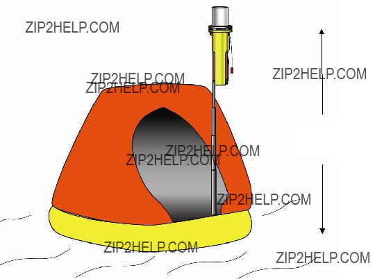
To deploy SART on board a distressed vessel, rather than a life raft, hang SART near vertical as high as possible, with a clear view of the horizon. The SART must not be obscured by metal bulkheads etc.

Installation

The SART should be mounted inside the vessel, next to an emergency exit. Some ships require 2 SARTs one by a port exit and one by a starboard exit. Mount each SART as follows . . .

???Mount in plain view, at a convenient height, so that all crew can easily remove the SART.

???Position at least 1 meter from the ship???s compass.

The SART mounting bracket should be bolted to a bulkhead using four (4) suitable M6 (1/4") bolts. The equipment does not include mounting hardware for the bracket, as it will depend on the bulkhead material and its thickness. Bracket mounting holes and SART mounting details are shown in figure 7.

To install SART:

Remove SART from its packaging and check for shipping damage.

Perform the SART test (see Testing and Maintenance procedures on page 15).

Select a position for SART Mounting allowing sufficient space for the assembly.

!NOTE: The SART contains magnetic material. Ensure that the position that you select is at least 3 feet (1 meter) away from compass installations.

Drill holes to dimensions shown on figure 7.

Place bracket in position and secure to bulkhead as follows:

Remove the SART from the bracket.

Position bracket at the correct position for maximum visibility

Mark position of bracket fixing holes.

Drill holes to suit mounting fixtures.

Secure bracket to bulkhead.

Mount SART on the bracket (see figure 7).

Secure SART with Velcro strap.

NOT TO SCALE

Figure 7: Installing the SART

10.0 Testing and Maintenance

The SART is a safety device; it must be regularly checked at least every 2 months as follows. . .

Visually inspect the casing for cracks & punctures.

Extend the pole and check that it operates correctly, and then return the pole to its housing.

Check to ensure the tether lanyard is neatly bundled and firmly secured to the SART.

Ensure the lanyard is NOT tied to any part of the vessel.

Check that the battery expiry label shows sufficient battery life to cover the next routine voyage (See figure 8).

Ensure the safety lock is in place and the integrity seal is not broken.

Confidence check

Push the switch ring to the left and into the test position and hold it there for 10 seconds. Confirm the SART does either (a) or (b) below, then release the switch.

a)Beeps once and the red light flashes continuously every 4 seconds (no Radar within range).

b)Beeps and the red light flashes every 1 second (Answering Radar).

Multiple SART Interrogation Test

If your vessel has two PathFinderTM3 SARTs on board they may be used to test each other. This test requires that each SART is held independently 5 meters away from one another. Turn and hold one SART into the TEST position. It will beep once and the red light flashes continuously every 4 seconds. Next place the 2nd SART into the test mode. Confirm that the 1st SART beeps once every time the 2nd SART is turned into the test mode.

Repeat this sequence to test the 2nd SART.

Functional Test (At least once a year carry out a functional test)

Get someone to watch the Radar screen, while you take the SART to the ship???s bow or at least 20m from the Radar antenna. Hold the switch in its TEST position for no more than 10 seconds. Confirm a "distress" pattern is generated on the Radar screen. At close range the pattern often appears as a series of concentric circles.

11.0 Servicing

If the SART fails any of its monthly checks, the SART must be returned to the supplier or an approved service agent for investigation and/or servicing.

If the battery is beyond its expiry date, the SART must be returned to a Battery Replacement Center for a battery change. The battery is NOT user serviceable; DO NOT attempt to change it.

If the SART has been used in an emergency or its integrity seal is broken, then the SART must be returned for a battery change.

Contact your local supplier; he can advise you on your local approved service agent. Otherwise, call ACR at 1-800-432-0227 or send mail correspondence to the Customer Service Manager at the address given in the front of this manual.

When returning your SART, ensure you follow the transportation instructions on page 16.

12.0 Battery Pack Replacement

Regulations require that the battery pack (P/N 2714.4) be replaced every 5 years. A label on the lower section of the SART housing shows the expiry date of the battery pack (see figure 8).

Replacement Battery label

Figure 8

!NOTE: The battery pack must be replaced if the SART has been used in an emergency or if the SART has been activated inadvertently (integrity seal broken).

!CAUTION: The battery pack CANNOT be recharged; attempts to recharge the battery pack could result in an explosion or fire.

Replacement of the SART battery pack must be performed by ACR or by an ACR Battery Repair Center. The cost of this replacement is the responsibility of the owner.

13.0 Transportation

Your SART contains a Lithium battery. International regulations on shipment of Lithium require special warning labels. When returning your SART, bring to an approved Hazmat shipper who will be familiar with the following instructions (for advice only). MSDS shipping sheets are available for downloading on our website www.acrelectronics.com.

1)Pack the SART in a strong cardboard box.

2)Write these words on the outside of the box . . .

4)Write your name and address on the box.

5)Check with your local transportation authority for additional or different requirements.

Contact your supplier or the manufacturer's Customer Service Manager with any queries on shipment.

Note SART Serial Number

The serial number on the SART is indicated on the base of the SART.

14.0Technical Specifications

General

Meets the requirements of:

0735/04 Designed to meet:

IMO Res. A.802(19), EC Council Directive 96/98/EC, Global Maritime Distress and Safety Systems (GMDSS) according to IMO amendment to Chapter III of the 1974 SOLAS Convention, as well as part 80 of the FCC Rules

RTCM Paper 111-92/SC113-36

(Ninth Draft SART Standard)

Electromagnetic Compatibility

Meets the applicable requirements of (BS) EN 60945: 1997.

15.0 Warranty

The SART or Replacement Battery is guaranteed by the manufacturer to be free of defects in materials and workmanship for a period of one year from the date of the original purchase. This warranty is extended only to the original purchaser of the unit.

During the warranty period the manufacturer will repair or, at the manufacturer's option, replace a defective unit at no cost to the owner of the SART for materials and labor. Transportation charges are the responsibility of the owner of the SART. The unit must be packaged correctly and shipped prepaid to the manufacturer or an authorized service center. It will be returned via collect shipping.

The warranty is void if the unit has been damaged through accident, misuse, improper installation, or during transportation. The warranty is also void if the security seal on the SART has been broken.

The liability of the manufacturer shall be limited to the repair or replacement of a defective unit during the warranty period. The manufacturer shall not be liable for injuries or damages arising from the handling, possession or use of this product by the purchaser or others that obtain it through the purchaser.

For full and complete warranty terms the owner is referred to the warranty card provided. To validate this warranty, the enclosed warranty card must be completed and mailed before putting the unit into service.

16.0 DECLARATION OF CONFORMITY

We hereby declare that the following product is in conformity with EU Directive 96/98EC Marine Equipment Directive 29th Dec. 1996, modified by EU Commission Directive 98/85/EC dated 11th Nov. 1998

Signed on behalf of ACR Electronics Inc.

Signed: _______________________________________

Name: John Flood Title: VP Engineering

Date: